Sélection de la langue

Search

Sommaire du brevet 2460555 

Énoncé de désistement de responsabilité concernant l'information provenant de tiers

Une partie des informations de ce site Web a été fournie par des sources externes. Le gouvernement du Canada n'assume aucune responsabilité concernant la précision, l'actualité ou la fiabilité des informations fournies par les sources externes. Les utilisateurs qui désirent employer cette information devraient consulter directement la source des informations. Le contenu fourni par les sources externes n'est pas assujetti aux exigences sur les langues officielles, la protection des renseignements personnels et l'accessibilité.

Disponibilité de l'Abrégé et des Revendications

L'apparition de différences dans le texte et l'image des Revendications et de l'Abrégé dépend du moment auquel le document est publié. Les textes des Revendications et de l'Abrégé sont affichés :

  • lorsque la demande peut être examinée par le public;
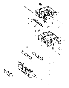
  • lorsque le brevet est émis (délivrance).
(12) Demande de brevet: (11) CA 2460555
(54) Titre français: DISTRIBUTRICE A BILLETS AUTOMATIQUE
(54) Titre anglais: AUTO-BILL-DISPENSING MACHINE
Statut: Réputée abandonnée et au-delà du délai pour le rétablissement - en attente de la réponse à l’avis de communication rejetée
Données bibliographiques
(51) Classification internationale des brevets (CIB):
  • G07F 09/00 (2006.01)
  • G07B 03/00 (2006.01)
  • G07F 07/10 (2006.01)
  • G07F 19/00 (2006.01)
  • G07G 05/00 (2006.01)
(72) Inventeurs :
  • YANG, YA-HUI (Taïwan, Province de Chine)
  • LIN, YI-CHIA (Taïwan, Province de Chine)
(73) Titulaires :
  • INTERNATIONAL CURRENCY TECHNOLOGIES CORPORATION
(71) Demandeurs :
  • INTERNATIONAL CURRENCY TECHNOLOGIES CORPORATION (Taïwan, Province de Chine)
(74) Agent: SMART & BIGGAR LP
(74) Co-agent:
(45) Délivré:
(22) Date de dépôt: 2004-03-10
(41) Mise à la disponibilité du public: 2004-09-28
Licence disponible: S.O.
Cédé au domaine public: S.O.
(25) Langue des documents déposés: Anglais

Traité de coopération en matière de brevets (PCT): Non

(30) Données de priorité de la demande:
Numéro de la demande Pays / territoire Date
092204897 (Taïwan, Province de Chine) 2003-03-28

Abrégés

Abrégé anglais


An auto-bill-dispensing machine is provided. The auto-bill-dispensing machine
comprises bill receiver having a plurality of security hooks positioned
axially between
two positioning plates formed on the two sides of the upper chassis of the
bill receiver,
and the security hooks are against within a plurality of blocking grooves of
the lower
chassis to block the bill passage. When the bill enters into the bill passage
and being held
against on the security hooks, the security hooks of the bill receiver will be
out of the
blocking groove of the lower chassis to let the bill pass through, and after
the bill passes
the security hooks, the security device will return to the original position
to make the
security hooks support within the blocking groove of the lower chassis to
prevent the bill
being pulled back by a string, a tape, a steel wire or a glued metallic plate.

Revendications

Note : Les revendications sont présentées dans la langue officielle dans laquelle elles ont été soumises.


WHAT THE INVENTION CLAIMED IS
1. An auto-bill-dispensing machine comprising:
a bill receiver comprising an upper chassis and a lower chassis, wherein
between
said upper chassis and lower chassis forms a bill passage, at the frontal
flange on each
side of said upper chassis forms a positioning element and a plurality of
blocking groove
is positioned at a central region of said lower chassis; and
a security device positioned axially within the bill receiver, wherein said
security
device comprises a base, wherein said base is movable in between the two sides
of said
upper chassis and said positioning element, and a plurality of security hooks
is formed at
the bottom flange of said base, said security hooks are movable and support
onto said a
plurality of blocking groove of lower chassis to block said bill passage.
2. The auto-bill-dispensing machine according to claim l, wherein said
positioning element of upper chassis has a through hole, and on the two sides
of said base
of security device has through holes so that said positioning element and said
base can be
assembled together by using an axle element to penetrate through said through
hole of
said positioning element and said through holes of said base.
3. The auto-bill-dispensing machine according to claim l, wherein said base of
the security device has a weight block on a top face.
4. The auto-bill-dispensing machine according to claim 1, wherein said
security
hook of the security device is in an arched pointed shape.
5. The auto-bill-dispensing machine according to claim 1, wherein said lower
chassis of bill receiver comprises a roller holder, and on said roller holder
has a first
roller set and a second roller set.
7

6. The auto-bill-dispensing machine according to claim l, wherein said first
roller
set and second roller set are supported an each other.
7. The auto-bill-dispensing machine according to claim l, wherein said first
roller
set and second roller set are made of a rubber material.
8. The auto-bill-dispensing machine according to claim l, wherein on each side
of
said upper chassis has a protrusion, on each corresponding side of said lower
chassis has
a fitting groove so that said protrusions of the upper chassis can fit into
said fitting
grooves of the lower chassis for positioning.
8

Description

Note : Les descriptions sont présentées dans la langue officielle dans laquelle elles ont été soumises.

CA 02460555 2004-03-10
AUTO-BILL-DISPENSING MACHINE
BACKGROUND OF THE INVENTION
I . The field of the invention
[OOOI] The present invention relates to an auto-bill-dispensing machine, and
more
S particularly relates to a bill receiver of a auto-bill-dispensing machine
comprising a
plurality of security hooks positioned axially between two positioning plates
formed on
the two sides of an upper chassis of the bill receiver, and the security hooks
are
positioned within and against a plurality of blocking grooves of the lower
chassis to block
the bill passage.
2. Description of the related art
[0002] With the rapid advancement and development in electronic industry, the
auto-bill-dispensing machines (such as card dispensing machine, ticketing
machine or
auto-changing machine) are installed in many public places far satisfying the
requirement
of the consumers as convenience and prompt service. The service provided by
these
machines are not only for substantially reducing the labor cost but also more
acceptable
to the consumers for the convenience provided. However, the general automatic
vending
machines will be under the supervision only in the routine manual storage
check-up or
maintenance, and when they are not under the supervision by the authorized
party, the
cards or bills therein can be stolen by using several methods. Referring to
the vending
machine of a prior art as shown in Fig. 6, which indicates that the
conventional bill
receiver comprises a frame A, on a side of the frame A has a receiving slot A1
for
receiving bills, and on the upper and lower side of the bill passage
positioned inside of
the frame A fixed with a circuit board B for identifying the bills and a motor
device C.
1

CA 02460555 2004-03-10
Further, at the exit A2 positioned with a security plate D for preventing the
bill being
pulled out after accepting by the bill receiver A1. As bill is made of soft
material and
gets damage when being pulled by force, such destructive activity can also
break down
the operation of the bill receiver. And if a thief uses a harder material, for
example, steel
wire, metallic plate or alike, to try to pull out the bill, the security
device of the
conventional is incapable of preventing the bills from being stolen.
According, it is
highly desirable to improve the structure of the bill receiver to overcome the
defects of
the prior art.
SUm~rIARY OF THE INVENTION
[0003] Accordingly, in the view of the foregoing, the present inventor makes a
detailed study of related art to evaluate and consider, and uses years of
accumulated
experience in this field, and through several experiments, to create a new
structure of a
bill receiver for an auto-bill- dispensing machine in order to improve the
security of the
auto-bill-dispensing machine to effectively prevent the bills from being
stolen.
[0004] According to one aspect of the present invention, a bill receiver
comprising
a plurality of security hooks positioned axially between two positioning
plates formed on
the two sides of the upper chassis of the bill receiver is provided, and the
security hooks
are positioned within and against a plurality of blocking grooves of the lower
chassis to
block the bill passage.
[0005]According to another aspect of the present invention, when the bill
enters
into the bill passage and is being held against the security hooks, the
security hooks of the
security device will be out of the blocking groove of the lower chassis to let
the bill pass
through, and after the bill passes the security hooks, the security device
will return to the
2

CA 02460555 2004-03-10
original position to make the security hooks support within the blocking
groove the lower
chassis, and thus preventing the bill from being pulled back by using a
string, a tape, a
steel wire or a glued metallic plate adhering onto the bill.
BRIEF DESCRIPTION OF THE DRAWINCr
[0006] For a more complete understanding of the present invention, reference
will
now be made to the following detailed description of preferred embodiments
taken in
conjunction with the accompanying drawings, in which:
[0007] Fig. 1 is an elevational view of an auto-bill-dispensing machine of the
present invention;
[0008]Fig. 2 is an exploded view of the auto-bill-dispensing machine of the
present invention;
[0009]Fig. 3 is a sectional view showing before the bill enters to the bill
receiver
of the present invention;
[0010]Fig. 4 is a sectional view showing when the bill enters into the bill
receiver
of the present invention;
[0011]Fig. 5 is a sectional view showing after the bill enters to the bill
receiver of
the present invention; and
[0012]Fig. 6 is a sectional view of a conventional auto-bill-dispensing
machine.
DETAILED DESCRIPTION OF PREFERRED EMBODIMENTS
[0013] Reference will be made in detail to the preferred embodiments of the
invention, examples of which are illustrated in the accompanying drawings.
Wherever
possible, the same reference numbers are used in the drawings and the
description to refer
to the same or Like parts.
3

CA 02460555 2004-03-10
[0014] Referring to Figs. l, 2 and 3, the auto-bill-dispensing machine of the
present invention comprises a bill receiver 1 and a security device 2
positioned axially
within the bill receiver 1. The bill receiver 1 comprises an upper chassis 11
and a lower
chassis 12, and on each side of the upper chassis 11 comprises a protrusion
111, and on
each corresponding side of the lower chassis 12 comprises a fitting groove
121, thus the
protrusions 111 of the upper chassis 11 can fit into the fitting groove 121 of
the lower
chassis 12 forming a bill passage 13 in between the upper chassis 11 and the
lower
chassis 12. Further, at the frontal flange of each side of the upper chassis
11 extends into
a positioning element 112 having a through hole 1121, and a plurality of
blocking
grooves 122 is formed at the central region of the lower chassis 12.
[0015]The security device 2 comprises a base 21, and at the bottom flange of
the
base 21 has a plurality of arched pointed security hooks 211. Further; on a
top face of the
base 21 comprises a projected weight block 212, and a plurality of through
holes 213 is
formed on the two sides of the base 21.
[0016]The feature provided by the above described embodiment is to fix the
security device 2 between the positioning elements 112 on the two sides of the
upper
chassis 11, and by using an axle element 3 to penetrate through the through
hole 1121 of
the positioning element 112 and the through hole 213 of the base 21 to further
position
the security device 2, thus the security device 2 is able to rotate at an
angle by using the
axle element 3 as an axis.
[0017]Furthermore, the lower chassis 12 of the bill receiver 1 comprises a
roller
holder 4, and a first roller set 41 and a second roller set 42 are positioned
on a top of the
roller holder 4 axially positioned, and the first roller set 41 and the second
roller set 42 on
4

CA 02460555 2004-03-10
the roller holder 4 are supported against each other and are positioned at the
exit of the
bill passage 13.
[0018]Referring to Figs. 3, 4 and 5, the actual operation of the bill receiver
of the
present invention is described. Before operating the bill receiver l, the
security hooks
211 of the security device 2 are supported onto the blocking groove 122 of the
lower
chassis 12 by the weight of the weight black 212, and also block in the bill
passage 13 is
positioned closing the bill passage 13. When the bill 5 enters into the bill
passage 13 of
the bill receiver 1, the frontal edge of the bill 5 is against and pushes the
arched side of
the security hooks 211 allowing the security hook 211 to rotate at an angle
and further to
release itself from the blocking groove 122 of the lower chassis 12, thus a
slit is created
in the bill passage 13 to let the bill S pass through. If a thief tries to use
a string, a tape, a
steel wire, a glued metallic plate or alike for attempting to steal the bill
5, the security
hooks 211 will effectively blocks the bill 5 from being removed by the above
mentioned
string, tape, steel wire, glued metallic plate or alike. And after the bill 5
passes through
the slit successfully, the security hooks 211 will return to the original
position
automatically under the influence of gravity due to the weight of the weight
block 212
and is supported by the blocking groove 122 of the lower chassis 12 and also
blocks the
bill passage 13 to close the bill passage 13, and therefore, the bill 5 is
effectively
prevented from being stolen by using a string, a tape, a steel wire, or a
glued metallic
plate or alike.
[0019] While the invention has been described in conjunction with a specific
best
mode, it is to be understood that many alternatives, modifications, and
variations will be
apparent to those skilled in the art in light of the foregoing description.
Accordingly, it is
5

CA 02460555 2004-03-10
intended to embrace all such alternatives, modifications, and variations in
which fall
within the spirit and scope of the included claims. All matters set forth
herein or shown in
the accompanying drawings are to be interpreted in an illustrative and non-
limiting sense.
6

Dessin représentatif
Une figure unique qui représente un dessin illustrant l'invention.
États administratifs

2024-08-01 : Dans le cadre de la transition vers les Brevets de nouvelle génération (BNG), la base de données sur les brevets canadiens (BDBC) contient désormais un Historique d'événement plus détaillé, qui reproduit le Journal des événements de notre nouvelle solution interne.

Veuillez noter que les événements débutant par « Inactive : » se réfèrent à des événements qui ne sont plus utilisés dans notre nouvelle solution interne.

Pour une meilleure compréhension de l'état de la demande ou brevet qui figure sur cette page, la rubrique Mise en garde , et les descriptions de Brevet , Historique d'événement , Taxes périodiques et Historique des paiements devraient être consultées.

Historique d'événement

Description Date
Inactive : CIB expirée 2019-01-01
Demande non rétablie avant l'échéance 2010-03-10
Le délai pour l'annulation est expiré 2010-03-10
Réputée abandonnée - omission de répondre à un avis sur les taxes pour le maintien en état 2009-03-10
Inactive : CIB de MCD 2006-03-12
Demande publiée (accessible au public) 2004-09-28
Inactive : Page couverture publiée 2004-09-27
Inactive : RE du <Date de RE> retirée 2004-08-18
Inactive : Demande ad hoc documentée 2004-08-17
Modification reçue - modification volontaire 2004-07-23
Requête d'examen reçue 2004-07-23
Inactive : CIB en 1re position 2004-05-18
Inactive : CIB attribuée 2004-05-18
Inactive : Certificat de dépôt - Sans RE (Anglais) 2004-04-15
Lettre envoyée 2004-04-15
Demande reçue - nationale ordinaire 2004-04-15

Historique d'abandonnement

Date d'abandonnement Raison Date de rétablissement
2009-03-10

Taxes périodiques

Le dernier paiement a été reçu le 2008-02-26

Avis : Si le paiement en totalité n'a pas été reçu au plus tard à la date indiquée, une taxe supplémentaire peut être imposée, soit une des taxes suivantes :

  • taxe de rétablissement ;
  • taxe pour paiement en souffrance ; ou
  • taxe additionnelle pour le renversement d'une péremption réputée.

Les taxes sur les brevets sont ajustées au 1er janvier de chaque année. Les montants ci-dessus sont les montants actuels s'ils sont reçus au plus tard le 31 décembre de l'année en cours.
Veuillez vous référer à la page web des taxes sur les brevets de l'OPIC pour voir tous les montants actuels des taxes.

Historique des taxes

Type de taxes Anniversaire Échéance Date payée
Taxe pour le dépôt - générale 2004-03-10
Enregistrement d'un document 2004-03-10
TM (demande, 2e anniv.) - générale 02 2006-03-10 2006-02-14
TM (demande, 3e anniv.) - générale 03 2007-03-12 2007-01-30
TM (demande, 4e anniv.) - générale 04 2008-03-10 2008-02-26
Titulaires au dossier

Les titulaires actuels et antérieures au dossier sont affichés en ordre alphabétique.

Titulaires actuels au dossier
INTERNATIONAL CURRENCY TECHNOLOGIES CORPORATION
Titulaires antérieures au dossier
YA-HUI YANG
YI-CHIA LIN
Les propriétaires antérieurs qui ne figurent pas dans la liste des « Propriétaires au dossier » apparaîtront dans d'autres documents au dossier.
Documents

Pour visionner les fichiers sélectionnés, entrer le code reCAPTCHA :


Pour visualiser une image, cliquer sur un lien dans la colonne description du document. Pour télécharger l'image (les images), cliquer l'une ou plusieurs cases à cocher dans la première colonne et ensuite cliquer sur le bouton "Télécharger sélection en format PDF (archive Zip)" ou le bouton "Télécharger sélection (en un fichier PDF fusionné)".

Liste des documents de brevet publiés et non publiés sur la BDBC .

Si vous avez des difficultés à accéder au contenu, veuillez communiquer avec le Centre de services à la clientèle au 1-866-997-1936, ou envoyer un courriel au Centre de service à la clientèle de l'OPIC.


Description du
Document 
Date
(aaaa-mm-jj) 
Nombre de pages   Taille de l'image (Ko) 
Description 2004-03-09 6 261
Abrégé 2004-03-09 1 28
Revendications 2004-03-09 2 75
Dessins 2004-03-09 6 161
Dessin représentatif 2004-07-21 1 13
Courtoisie - Certificat d'enregistrement (document(s) connexe(s)) 2004-04-14 1 105
Certificat de dépôt (anglais) 2004-04-14 1 158
Rappel de taxe de maintien due 2005-11-13 1 109
Courtoisie - Lettre d'abandon (taxe de maintien en état) 2009-05-04 1 172
Taxes 2006-02-13 1 27
Taxes 2007-01-29 1 28
Taxes 2008-02-25 1 36