Note: Descriptions are shown in the official language in which they were submitted.
128901
CA 02460662 2004-03-11
METHODS AND APPARATUS FOR ASSEMBLING
GAS TURBINE ENGINES
BACKGROUND OF THE Il~~VENTION
This invention relates generally to gas turbine engines, more particularly to
methods
and apparatus for assembling gas turbine engines.
At least some known gas turbine engines include, in serial flow arrangement, a
fan
assembly and a high pressure compressor which compress airflow entering the
engine,
a combustor which burns a mixture of fuel and air, and low and high pressure
rotary
assemblies which each include a plurality of rotor blades that extract
rotational energy
from airflow exiting the combustor. The fan assembly includes a plurality of
circumferentially-spaced fan blades that extend radially outwardly from an
annular fan
disk. A spinner is coupled to a front end of the fan assembly to facilitate
providing
smooth airflow into the fan assembly.
Known spinners are coupled directly to the disk by a plurality of
circumferentially-
spaced threaded studs. The studs are axially and radially secured to the disk
prior to
the spinner being coupled to the fan assembly. Additionally, securing the
studs to the
disk prevents the studs from rotating such that nuts used to couple the
spinner to the
disk can be tightened. To secure known studs to the disk, initially each stud
is riveted
to a wingbolt member. The wingbolt member is then riveted to the disk.
Coupling the spinner to the disk may be a time-consuming process, as the
riveting and
drilling processes must each be precise to prevent inadvertent damage to the
disk.
Specifically, each wingbolt.member requires three holes to be formed in the
fan disk,
wherein two of the holes are countersunk and are drilled into the fan disk for
each set
of rivets used to couple the wingbolt members to the disk, and one of the
openings is
drilled into the fan disk to receive the threaded stud therethrough. As a
result, the
assembly process may be time-consuming and costly.
-1-
128901
CA 02460662 2004-03-11
BRIEF DESCRIPTION OF THE INVENTION
In one aspect, a method for assembling a gas turbine engine is provided. The
method
comprises forming at least one substantially elliptically-shaped opening
within a
flange extending from a fan disk, inserting a fastener including a first body
portion, a
second body portion, and an anti-rotation stop extending therebetween, at
least
partially through the at least one flange opening, and coupling the fastener
to the
flange such that the fastener stop is positioned within the at least one
flange opening.
In another aspect, a fan assembly for a gas turbine engine is provided. The
fan
assembly comprises a fan disk, and an annular forward extension. The fan disk
includes a plurality of hubs coupled to a disk rim by a p:Lurality of webs.
The forward
extension includes a flange, and the forward extension extends forwardly from
an
upstream most of the webs. The flange includes a plurality of
circumferentially
spaced openings extending therethrough. At least one of the openings is
substantially
elliptically-shaped.
In a further aspect, a fan assembly is provided. The fan assembly includes a
fan disk,
at least one fastener, and a spinner. The at least one fastener includes a
first body
portion, a second body portion, and an anti-rotation stop extending
therebetween. ,The
spinner is coupled to the fan disk by the at least one fastener.
BRIEF DESCRIPTION OF 'THE DRAWTNGS
Figure 1 is a schematic of a gas turbine engine;
Figure 2 is a cross-sectional illustration of a portion of the gas turbine
engine shown in
Figure 1;
Figure 3 is a perspective view of a portion of a fan disk shown in Figure 2;
and
Figure 4 is a perspective view of a fastener shown in Figure 2.
DETAILED DESCRIPTION OF THE INVENTION
Figure 1 is a schematic illustration of a gas turbine engine 10 including a
fan assembly
12, a high pressure compressor 14, and a combustor 1~5. In one embodiment,
engine
-2-
128901
CA 02460662 2004-03-11
is a CF34 engine available from General Electric Company, Cincinnati, Ohio.
Engine 10 also includes a high pressure turbine 18 and a low pressure turbine
20. Fan
assembly 12 and turbine 20 are coupled by a first shaft 24, and compressor 14
and
turbine 18 are coupled by a second shaft 26.
In operation, air flows through fan assembly 12 and compressed air is supplied
from
fan assembly 12 to high pressure compressor 14. T'he highly compressed air is
delivered to combustor 16. Airflow from combustor 16 drives rotating turbines
18
and 20 and exits gas turbine engine 10 through an exhaust system 28.
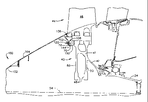
Figure 2 is a cross-sectional illustration of a portion of. fan assembly 12
including a
fan disk 40. Figure 3 is a perspective view of a portion of fan disk 40.
Figure 4 is a
perspective view of a fastener 120 used with fan assembly 12. Fan disk 40 is
coupled
to shaft 24 by an aft extension 42, and includes a row 44 of circumferentially-
spaced
apart fan blades 46 that extend radially outwardly from fan disk 40. More
specifically, fan disk 40 is a mufti-bore disk that includes a radially outer
rim 47
attached to a plurality of disk hubs 48 by a corresponding number of webs 50
that
circumscribe a centerline 54 of engine 10. In the exemplary embodiment, two
hubs
48 are illustrated.
An annular forward extension 70 including an annular forward flange 72 extends
upstream from a forward most web 50. In one embodiment, flange 72 is coupled
to
web 50. Alternatively, flange 72 is formed integrally with web 50. Flange 72
includes a plurality of circumferentially-spaced openings 80 extending
therethrough.
More specifically, in the exemplary embodiment, flange 72 includes fourteen
circumferentially-spaced openings 80.
Each opening 80 extends from an upstream side 84 of flange 72 to a downstream
side
86 of flange 72. Openings 80 are substantially elliptically-shaped such that a
major
elliptical axis 88 is aligned substantially radially with respect to fan disk
40. More
specifically, openings 80 are counter-bored such that a counter-bored ledge 90
circumscribes each respective opening 80 along flange upstream side 84. Ledge
90
has a width Wl measured between opening 80 and an counter-bored sidewall 92,
and
-3-
. 128901
CA 02460662 2004-03-11
is recessed a distance D~ with respect to an outer surface 94 of flange
upstream side
84.
A spinner 100 is coupled to disk 40 by forward flange '72. Specifically,
spinner 100
includes a forward conical section 102 and an aft conical section 104 that
extends
aftward from forward conical section 102. Spinner I00 facilitates smoothing
airflow
channeled towards fan asserilbly 12. Aft conical section 104 includes an aft
flange
assembly 106 that includes a plurality of circumferentially-spaced openings
108 that
enable spinner 100 to be coupled to fan disk 40. Flange assembly 106 and
forward
flange 72 facilitate accommodating radial growth differential between disk 40
and
spinner 100.
A plurality of fasteners or spinner bolts 120 are used to couple spinner 100
to disk 40
through forward flange 72. Each fastener 120 includes a first body portion or
shank
I22 and a second body portion or shank 124 separated by an anti-rotation stop
126
that has a width Ws. In the exemplary embodiment, stop 126 is formed
integrally
with shanks 122 and I24. Also in the exemplary embodiment, shanks 122 and 124
are identical and each includes a plurality of threads 128 extending from stop
126 to a
respective end 130 and 132 of each shank 122 and 124. Alternatively, shanks
122 and
124 are non-identical.
Each shank 122 and 124 has a substantially circular cross-sectional profile.
More
specifically, each shank 122 and 124 has a diameter DZ that is smaller than a
length Ll
of a minor axis 136 defining each forward flange opening 80. In contrast,
fastener
stop 126 has a non-circular cross-sectional profile that is substantially
identically sized
to the cross-sectional profile defined by opening 80. For example, in the
exemplary
embodiment, fastener stop 126 is substantially elliptically-shaped and has a
major axis
length S1 that is slightly smaller than a corresponding length L3 of opening
axis 88,
and has a minor axis length (not shown) that is slightly smaller than minor
axis length
Ll.
Stop width Ws is measured between opposing downstream side 140 and shoulder
146,
and is approximately equal to a width of Wo of each opening 80 measured
between
ledge 90 and a downstream outer surface 144 of flange 72. Fastener stop 126
also
_4_
128901
CA 02460662 2004-03-11
includes an annular shoulder 146 that extends radially outwardly and
circumscribes
stop 126. More specifically, shoulder 146 has a width WS that is slightly
smaller than
ledge width Wl, and a thickness TS that is approximately equal to ledge
recessed
distance Di. Shoulder 146 also has a cross-sectional profile that is sized
substantially
identically to a cross sectional profile defined by counter-bored ledge 90.
During assembly of fan assembly 12; initially openings 80 are formed by
drilling fan
disk forward flange 72. In another embodiment, if an existing fan assembly is
being
retrofitted or repaired, existing fastener openings are reshaped to form
openings 80.
Each fastener 120 is then positioned within a respective disk flange opening
80 such
that shank 122 and stop 126 are inserted at least partially through opening
80. More
specifically, when fastener 120 is fully inserted, stop 126 remains positioned
within
opening 80 and stop shoulder 146 is positioned against ledge 90 and within
recess Dl.
Accordingly, stop shoulder 146 and ledge 90 not only facilitate positioning
fastener
120 with respect to flange 72, but shoulder 146 and ledge 90 also facilitate
aligning
fastener 120 with resect to flange 72. More specifically, shoulder 146
prevents
fastener 120 from being improperly axially inserted through opening 80, and
also
facilitates proper radial positioning of fastener 120 with respect to flange
72. For
example, if fastener 120 is rotated 180° within opening 80, shanks 122
and 124 will
be radially offset such that spinner 100 can not be mated against flange 72.
After fastener 120 is positioned within opening 80, a nut 150 is threadably
coupled to
shank 122 and is tightened against flange outer surface 144 such that fastener
120 is
securely coupled to flange 72. More specifically, when fully coupled in
position,
fastener downstream side 140 is substantially flush with flange outer surface
144, and
fastener upstream side 142 is substantially flush with flange outer- surface
94.
Spinner 100 is then coupled to fan disk 40 using fasteners 120. Specifically,
spinner
aft conical section 104 is then positioned adjacent flange 72 such that each
respective
fastener shank 124 is inserted through each respective spinner opening 108. A
nut
152 is then threadably coupled to shank 124 and is tightened to secure spinner
100 to
fan disk 40. Because shanks 122 and 124 are identical, in the exemplary
embodiment,
nuts 150 and 152 are identical and are interchangeable, such that assembly
times may
-5-
128901
CA 02460662 2004-03-11
be reduced. Once fan assembly 12 is assembled, loading induced between spinner
100 and fan disk 40 is carried by fastener shanks 122 and 124.
During assembly, fastener stop shoulder 146 prevents rotation of fastener 120
within
each respective flange opening 80. Furthermore, because shoulder 146 prevents
rotation of fasteners 120 within openings 80; riveting operations are no
longer
necessary to couple spinner 100 to fan disk 40. Accordingly, only one third,
or
fourteen, openings 80 must be drilled within disk flange '72.
The above-described fastener provides a cost-effective and reliable method for
coupling a spinner to a fan disk. More specifically, the fasteners include a
pair of
opposing threaded shanks that are separated by an anti-rotation stop. When a
fastener
is secured within a counter-bored opening formed in the fan disk forward
flange, the
fastener shoulder prevents the fastener from rotating within the opening both
during
assembly, and after the spinner is coupled to the fan disk. Furthermore, the
fastener
stop also facilitates aligning each fastener with respect to the fan disk. As
a result, the
fastener facilitates reducing assembly costs of the fan assembly in a cost-
effective and
reliable manner.
Exemplary embodiments of fan assemblies are described above in detail. The fan
assemblies are not limited to the specific embodiments described herein, but
rather,
components of each assemhly may be utilized indep<~ndently and separately from
other components described herein. For example, each. fastener component can
also
be used in combination with other fan assembly and engine components, and in
combination with the other fan assembly components described herein.
While the invention has been described in terms of various specific
embodiments,
those skilled in the art will recognize that the invention can be practiced
with
modification within the spirit and scope of the claims.
-6-