Note: Descriptions are shown in the official language in which they were submitted.
CA 02460674 2004-03-16
WO 03/030227 PCT/US02/31436
-1-
METHOD OF SEMICONDUCTOR NANOPARTICLE SYNTHESIS
TECHNICAL FIELD
This invention relates to nanoparticles. More particularly, the invention
relates to
methods for making and using semiconductor nanoparticles. The invention finds
utility in
a variety of fields, including biology, analytical and combinatorial
chemistry, medical
diagnostics, and genetic analysis.
BACKGROUND ART
0 Semiconductor nanocrystals (also known as quantum dot particles) whose radii
are
smaller than the bulk exciton Bohr radius constitute a class of materials
intermediate
between molecular and bulk forms of matter. Quantum confinement of both the
electron
and hole in all three dimensions leads to an increase in the effective band
gap of the
material with decreasing crystallite size. Consequently, both the optical
absorption and
emission of semiconductor nanocrystals shift to the blue (higher energies) as
the size of
the nanocrystals gets smaller.
Semiconductor nanocrystals are nanoparticles composed of an inorganic,
crystalline semiconductive material and have unique photophysical,
photochemical and
nonlinear optical properties arising from quantum size effects, and have
therefore attracted
?0 a great deal of attention for their potential applicability in a variety of
contexts, e.g., as
detectable labels in biological applications, and as useful materials in the
areas of
photocatalysis, charge transfer devices, and analytical chemistry. As a result
of the
increasing interest in semiconductor nanocrystals, there is now a fairly
substantial body of
literature pertaining to methods for manufacturing such nanocrystals.
In general, these routes can be classified as involving preparation in glasses
(Ekimov et al., JETP Letters 34:345 (1981)); aqueous preparation, including
preparations
that involve use of inverse micelles, zeolites, Langmuir-Blodgett films, and
chelating
polymers (Fendler et al., J. Chem. Society, Chemical Communications 90:90
(1984) and
Henglein et al., Bef°. Bunsenges. Phys. Chem. 88:969 (1984)); and high
temperature
30 pyrolysis of organometallic semiconductor precursor materials, i.e., rapid
injection of
precursors into a hot coordinating solvent (Murray et al., J. AnZ. Chern. Soc.
115:8706
CA 02460674 2004-03-16
WO 03/030227 PCT/US02/31436
_2_
(1993) and I~atari et al., J. Phys. Chem. 98:4109 (1994)). The two former
methods yield
particles that have unacceptably low quantum yields for most applications, a
high degree
of polydispersity, poor colloidal stability, a high degree of internal
defects, and poorly
passivated surface trap sites. In addition, nanocrystals made by the first
route are
physically confined to a glass matrix and cannot be further processed after
synthesis.
Improved synthesis conditions have been reported that utilize cadmium salts
(Peng,
et al., J. Am. Chem. Soc. 123:183-184 (2001)). These conditions provide
certain
advantages over the rapid injection method. The use of cadmium acetate,
cadmium oxide
or other such Cd(II) salts, pre-complexed with a ligand such as
tetradecylphosphonic acid
provides for a cadmium precursor that is particularly suitable for nanocrystal
synthesis.
These reactions have numerous desirable features, including improved safety
and
relatively wide tolerance for production variables such as precursor injection
rate and
temperature. Of particular note is that these reactions can be tuned to yield
very narrow
photoluminescence spectra over a wide range of useful wavelengths.
Unfortunately, it is
difficult to optimize the particle yield, while maintaining the desirable
features of the
Cd(II) synthesis conditions. In particular, for smaller size nanoparticle
synthesis, yields
have been very poor under Cd(II) synthesis conditions. Reaction conditions
that provide
such low yields are not only more expensive to implement on a manufacturing
scale, but
they often require much larger reactors and produce more hazardous waste:
Thus, there remains a need in the art for improved methods for manufacturing
nanoparticles, and smaller nanoparticles in particular. Such methods would
ideally
provide a high product yield of internally defect free, high band edge
luminescence
nanoparticles with no or minimal trapped emission. Such methods would also
ideally
provide for the manufacture of particles that exhibit near monodispersity and
have a
relatively narrow particle size distribution. Finally, such methods would be
useful not
only with semiconductor nanoparticles, but also with other types of
nanoparticles, e.g.,
semiconductive nanoparticles that are not necessarily crystalline and metallic
nanoparticles.
CA 02460674 2004-03-16
WO 03/030227 PCT/US02/31436
-3-
The present invention addresses those needs by providing improved methods for
manufacturing nanoparticles. By controlling the nucleation density the methods
of the
invention provide for a predictable and controllable final particle size, as
well as many of
the aforementioned properties.
DISCLOSURE OF THE INVENTION
One aspect of the invention relates to a method of producing nanoparticles
comprising: (a) mixing a first precursor and at least one coordinating solvent
to form a first
mixture; (b) exposing the first mixture to a reaction promoter selected from
the group
0 consisting of oxygen and a reducing agent; (c) heating the first mixture to
a temperature
that is sufficiently high to form nanoparticles (nucleation crystals) when a
second
precursor is added; (d) introducing a second precursor into the first mixture
to form a
second mixture thereby resulting in the formation of a plurality of
nanoparticles; and (e)
cooling the second mixture to stop further growth of the nanoparticles.
Another embodiment of the invention is a method of producing nanoparticles
comprising: (a) mixing a first precursor and a second precursor with at least
one
coordinating solvent to form a first mixture; (b) heating the first mixture to
a temperature
that is sufficiently high to form nanoparticles when a reaction promoter is
added; (c)
exposing the first mixture to a reaction promoter, the reaction promoter being
selected
?0 from the group consisting of oxygen and a reducing agent, to form a second
mixture
thereby resulting in the formation of a plurality of nanoparticles; and (d)
cooling the
second mixture to stop further growth of the nanoparticles.
Yet another embodiment of the invention is a method of producing the
nanoparticle
shell comprising (a) mixing nanoparticles with at least one coordinating
solvent to form a
25 first mixture; (b) heating the first mixture to a temperature that is
sufficiently high to form
a shell on the nanoparticles when first and second precursors are added; (c)
introducing
first and second precursors into the first mixture to form a second mixture
thereby
resulting in the formation of shells on a plurality of nanoparticles; and (d)
cooling the
second mixture to stop further growth of the shell; wherein the method further
comprises
30 exposing the first or second mixture to a reaction promoter selected from
the group
consisting of oxygen and a reducing agent. The nanoparticles can be produced
by the
CA 02460674 2004-03-16
WO 03/030227 PCT/US02/31436
-4-
methods described herein or can be produced by any method known in the art.
Another aspect of the invention pertains to a method of producing
semiconductive
nanoparticles having a valency "n", comprising: (a) mixing a first precursor
having a
valency "c" and at least one coordinating solvent to form a mixture; (b)
exposing the
S mixture to a reaction promoter wherein the reaction promoter converts the
valency of the
first precursor to a valency "a"; (c) heating the mixture to a temperature
that is sufficiently
high to form nanoparticles when a second precursor is added; (d) introducing a
second
precursors into the mixture to form a second mixture thereby resulting in the
formation of
a plurality of nanoparticles; wherein the second precursor has a valency "b",
and wherein
0 a+b = n and c+b ~ n; and (e) cooling the second mixture to stop further
growth of the
nanoparticles.
BRIEF DESCRIPTION OF THE DRAWINGS
FIG. l and FIG. 2 are graphical representations of the effect on temporal
wavelength evolution during the course of a CdSe nanocrystal core-forming
reaction as a
function of added reaction promoter, as described in Examples 1 and 2. FIG. 1
shows the
effect on emission peak wavelength, while FIG. 2 shows the effect on the full
peak width
at half maximum (FWHM).
FIG. 3 and FIG. 4 are graphical representations of the effect of increasing
amounts
?0 of diphenylphosphine (DPP) on emission peak wavelength and FWHM as
described in
Example 1.
FIG. 5 is a graphical representation of the particle counts recovered from
each of
the reactions shown in the FIG. 2 and illustrates the level of control
afforded by the use of
reaction promoters.
ZS FIG. 6 is a graphical representation of the effect of the time of air
exposure prior to
the TOPSe injection as described in Example 3. The scale on the left-hand
coordinate is
the emission peak wavelength in nanometers and the right-hand ordinate is the
FWHM
peak height in nanometers.
FIG. 7 is a graphical representation of the effect of a spike of air-exposed
TOP
30 before the TOPSe injection as described in Example 5.
CA 02460674 2004-03-16
WO 03/030227 PCT/US02/31436
-5-
FIG. 8 is an illustration of one implementation of an electrochemical system
which
could be used to prepare nanocrystals by the methods described here.
DETAILED DESCRIPTION OF THE INVENTION
The present invention provides an improved method of producing nanoparticles
having a means for controlling the reactivity of a solution of nanoparticle
precursors
through introduction of a reaction promoter prior to the nucleation of
nanoparticles. This
control of reactivity allows for control of the relative number of
nanoparticle nuclei
formed in a single nucleation period. Control of nucleation density provides
for a
0 predictable and controllable final nanoparticle size, size distribution and
yield. In addition,
the method also provides for control of the growth rate once nucleation
occurs, which
allows for control of size focusing, resulting in very narrow size
distributions. The
methods described herein can be used to form the nanoparticle core, the
nanoparticle shell,
or both. In addition, the methods described herein can be used to form
nanoparticles that
are smaller than has been possible using traditional methods lenown in the
art, e.g., for
preparing CdSe nanoparticles which emit with an emission maximum in the range
of 400
nm to 500 nm.
In general, the invention provides a method of producing nanoparticles by
contacting a first precursor M' (valency = c) with a reaction promoter,
wherein the reaction
'0 promoter converts M' to M (valency = a); and then contacting the M
precursor with a
second precursor X (valency = b) to produce nanoparticles having a valency
"n", wherein
c+b ~ n and a+b = n.
Either the first elemental component or the second elemental component of the
nanoparticle can gain electrons. Therefore, the resulting nanoparticle can
have a
?5 composition of MX or XM, as exemplified below. For example, the method of
the
invention can be used for the production of CdSe nanoparticles, i.e., MX
nanoparticles
where n = 0. The first precursor M' can be Cd+2 (c = +2). Upon reaction with a
reaction
promoter of the invention, such as DPP or hydroquinone, Cd+2 is converted or
reduced to
Cd° (M, where a = 0). This is then contacted with the second precursor
Se° (X, where b =
30 0) to produce the CdSe nanoparticles having a valency of 0.
CA 02460674 2004-03-16
WO 03/030227 PCT/US02/31436
-6-
Cd+2 + reaction promoter ~ Cd°
Cd° + Se° ~ CdSe
The method of the invention can also be used for the production of, for
example, InP
nanoparticles, i.e., XM nanoparticles where n = 0. The first precursor M' can
be P° (c = 0).
Upon reaction with a reaction promoter of the invention, such as DPP or
hydroquinone, P°
is converted or reduced to P-3 (M, where a = -3). This is then contacted with
the second
precursor In+3 (X, where b = ~3) to produce the InP nanoparticles having a
valency of 0.
P° + reaction promoter -~ P-3
p In+3 + P-3 -> InP
Accordingly, one embodiment of the invention is a method of producing
semiconductive nanoparticles having a valency "n", comprising: (a) mixing a
first
precursor having a valency "c" and at least one coordinating solvent to form a
first
mixture; (b) exposing the first mixture to a reaction promoter wherein the
reaction
promoter converts the valency of the first precursor to a valency "a"; (c)
heating the first
mixture to a temperature that is sufficiently high to form nanoparticles when
a second
precursor is added; (d) introducing a second precursor into the mixture to
form a second
mixture thereby resulting in the formation of a plurality of nanoparticles;
wherein the
second precursor has a valency "b", and wherein a+b = n and c+b ~ n; and (e)
cooling the
!0 second mixture to stop further growth of the nanoparticles.
More specifically, in one embodiment of the invention, the method of producing
nanoparticles is a one-pot synthesis technique that involves: (a) mixing a
first precursor, an
optional ligand and at least one coordinating solvent to form a first mixture;
(b) exposing
the first mixture to a reaction promoter; (c) heating the first mixture to a
temperature that
?5 is sufficiently high to form nanoparticles, i.e., nucleation crystals, when
a second precursor
is added; (d) introducing a second precursor into the first mixture to form a
second mixture
thereby resulting in the formation of a plurality of nanoparticles; and (e)
cooling the
second mixture to stop further growth of the nanoparticles. A reducing agent
or oxygen
source serves as the reaction promoter.
30 The exposure to a reaction promoter provides for a higher yield of
nanoparticles,
typically up to three times more yield, more preferably up to 19 times better
yield when
CA 02460674 2004-03-16
WO 03/030227 PCT/US02/31436
_7_
compared to those methods where no reaction promoter is used. In addition, the
nanoparticle yield can be modulated by modulating the amount of reaction
promoter added
for the length of time of exposure.
The methods described herein can provide nanoparticles having an average
particle
diameter within the range of about 1.5 to 15 ~, with a particle size deviation
of less that
about 10% rms in diameter.
The methods described herein are particularly useful for preparing a
monodisperse
population of CdSe nanoparticles having an emission peak wavelength that is
preferably
less than about 570 nm, preferably less than about 520 nm, more preferably
less than about
l0 500 nm.
In addition, the methods described herein can provide a monodisperse
population
of nanoparticles having an emission peak wavelength that is less than about 35
nm at full
width at half max (FWHM), preferably less than about 30 nm FWHM, more
preferably
less than about 25 nm FWHM.
I. DEFINITIONS AND NOMENCLATURE
Before describing detailed embodiments of the invention, it is to be
understood that
unless otherwise indicated, this invention is not limited to specific
nanoparticle materials
or manufacturing processes, as such may vary. It may be useful to set forth
definitions
that are used in describing the invention. The definitions set forth apply
only to the terms
as they are used in this patent and may not be applicable to the same terms as
used
elsewhere, for example in scientific literature or other patents or
applications including
other applications by these inventors or assigned to common owners. The
following
description of the preferred embodiments and examples are provided by way of
explanation and illustration, and is not intended to be limiting.
It must be noted that, as used in this specification and the appended claims,
the
singular forms "a", "an" and "the" include plural referents unless the context
clearly
dictates otherwise. Thus, for example, reference to "a nanoparticle" includes
a single
nanoparticle as well as two or more nanoparticles, and the like.
In describing and claiming the 'present invention, the following terminology
will be
used in accordance with the definitions set out below.
CA 02460674 2004-03-16
WO 03/030227 PCT/US02/31436
_g_
The term "nanoparticle" refers to a particle, generally a semiconductive
particle,
having a diameter in the range of about 1-1000 nm, preferably in the range of
about 2-50
nm, more preferably in the range of about 2-20 nm.
The terms "semiconductor nanoparticle" and "semiconductive nanoparticle" refer
to a nanoparticle as defined herein, that is composed of an inorganic
semiconductive
material, an alloy or other mixture of inorganic semiconductive materials, an
organic
semiconductive material, or an inorganic or organic semiconductive core
contained within
one or more semiconductive overcoat layers.
The terms "semiconductor nanocrystal," "quantum dot" and "Qdot~ nanocrystal"
0 are used interchangeably herein to refer to semiconductor nanoparticles
composed of an
inorganic crystalline material that is luminescent (i.e., they are capable of
emitting
electromagnetic radiation upon excitation), and include an inner core of one
or more first
semiconductor materials that is optionally contained within an overcoating or
"shell" of a
second inorganic material. A semiconductor nanocrystal core surrounded by an
inorganic
l5 shell is referred to as a "core/shell" semiconductor nanocrystal. The
surrounding shell
material will preferably have a bandgap energy that is larger than the bandgap
energy of
the core material and may be chosen to have an atomic spacing close to that of
the core
substrate.
The term "solid solution" is used herein to refer to a compositional variation
that is
ZO the result of the replacement of ions or ionic groups with other ions or
ionic groups, e.g.,
CdS in which some of the Cd atoms have been replaced with Zn. This is in
contrast to a
"mixture," a subset of which is an "alloy," which is used herein to refer to a
class of matter
with definite properties whose members are composed of two or more substances,
each
retaining its own identifying properties.
By "luminescence" is meant the process of emitting electromagnetic radiation
(light) from an object. Luminescence results when a system undergoes a
transition from
an excited state to a lower energy state with a corresponding release of
energy in the form
of a photon. These energy states can be electronic, vibrational, rotational,
or any
combination thereof. The transition responsible for luminescence can be
stimulated
30 through the release of energy stored in the system chemically or added to
the system from
an external source. The external source of energy can be of a variety of types
including
CA 02460674 2004-03-16
WO 03/030227 PCT/US02/31436
-9-
chemical, thermal, electrical, magnetic, electromagnetic, and physical, or any
other type of
energy source capable of causing a system to be excited into a state higher in
energy than
the ground state. For example, a system can be excited by absorbing a photon
of light, by
being placed in an electrical field, or through a chemical oxidation-reduction
reaction. The
energy of the photons emitted during luminescence can be in a range from low-
energy
microwave radiation to high-energy x-ray radiation. Typically, luminescence
refers to
photons in the range from UV to IR radiation, and usually refers to visible
electromagnetic
radiation (i.e., light).
The term "monodisperse" refers to a population of particles (e.g., a colloidal
0 system) wherein the particles have substantially identical size and shape.
For the purpose
of the present invention, a "monodisperse" population of particles means that
at least about
60% of the particles, preferably about 75-90% of the particles, fall within a
specified
particle size range. A population of monodisperse particles deviates less than
10% rms
(root-mean-square) in diameter and preferably less than 5% rms.
5 The phrase "one or more sizes of nanoparticles" is used synonymously with
the
phrase "one or more particle size distributions of nanoparticles." One of
ordinary skill in
the art will realize that particular sizes of nanoparticles such as
semiconductor nanocrystals
are actually obtained as particle size distributions.
By use of the term "narrow wavelength band" or "narrow spectral linewidth"
with
?0 regard to the electromagnetic radiation emission of the semiconductor
nanocrystal is meant
a wavelength band of emissions not exceeding about 60 nm, and preferably not
exceeding
about 30 nm in width, more preferably not exceeding about 20 nm in width, and
symmetric about the center. It should be noted that the bandwidths referred to
are
determined from measurement of the full width of the emissions at half peak
height
ZS (FWHM), and are appropriate in the emission range of 200-2000 nm.
By use of the term "a broad wavelength band," with regard to the excitation of
the
semiconductor nanocrystal is meant absorption of radiation having a wavelength
equal to,
or shorter than, the wavelength of the onset radiation (the onset radiation is
understood to
be the longest wavelength (lowest energy) radiation capable of being absorbed
by the
30 semiconductor nanocrystal). This onset occurs near to, but at slightly
higher energy than
the "narrow wavelength band" of the emission. This is in contrast to the
"narrow
CA 02460674 2004-03-16
WO 03/030227 PCT/US02/31436
-10-
absorption band" of dye molecules, which occurs near the emission peak on the
high
energy side, but drops off rapidly away from that wavelength and is often
negligible at
wavelengths further than 100 nm from the emission.
The term "emission peak" refers to the wavelength of light within the
characteristic
emission spectra exhibited by a particular semiconductor nanocrystal size
distribution that
demonstrates the highest relative intensity.
The term "alkyl" as used herein refers to a branched or unbranched saturated
hydrocarbon group of 1 to approximately 24 carbon atoms, such as methyl,
ethyl, n-
propyl, isopropyl, h-butyl, isobutyl, t-butyl, octyl, decyl, tetradecyl,
hexadecyl, eicosyl and
0 tetracosyl, as well as cycloalkyl groups such as cyclopentyl and cyclohexyl.
Similarly,
alkanes are saturated hydrocarbon compounds such as methane, ethane, and so
forth. The
term "lower alkyl" is intended to mean an alkyl group of 1 to 4 carbon atoms,
and thus
includes methyl, ethyl, h-propyl, isopropyl, n-butyl, isobutyl and t-butyl.
The term "alkene" as used herein refers to a branched or unbranched
hydrocarbon
compound typically although not necessarily containing 2 to about 24 carbon
atoms and at
least one double bond, such as ethylene, h-propylene, isopropylene, butene,
butylene,
propylene, octene, decylene, and the like. Generally, although not
necessarily, the alkenes
used herein contain 2 to about 29 carbon atoms, preferably about 8 to about 20
carbon
atoms. The term "lower alkene" is intended to mean an alkene of 2 to 4 caxbon
atoms.
'0 The term "alkyne" as used herein refers to a branched or unbranched
hydrocarbon
group typically although not necessarily containing 2 to about 24 carbon atoms
and at least
one triple bond, such as acetylene, allylene, ethyl acetylene, octynyl,
decynyl, and the like.
Generally, although again not necessarily, the alkynes used herein contain 2
to about 12
carbon atoms. The term "lower alkyne" intends an alkyne of 2 to 4 carbon
atoms,
ZS preferably 3 or 4 carbon atoms.
II. PRECURSORs
There are numerous inorganic materials that are suitable for use as materials
for the
core and/or shell of semiconductor nanoparticles. These include, by way of
illustration
30 and not limitation, materials comprised of a first element selected from
Groups 2 and 12 of
the Periodic Table of the Elements and a second element selected from Group 16
(e.g.,
CA 02460674 2004-03-16
WO 03/030227 PCT/US02/31436
-11-
ZnS, ZnSe, ZnTe, CdS, CdSe, CdTe, HgS, HgSe, HgTe, MgS, MgSe, MgTe, CaS, Case,
Care, SrS, SrSe, SrTe, BaS, Base, Bare, and the like); materials comprised of
a first
element selected from Group 13 of the Periodic Table of the Elements and a
second
element selected from Group 15 (GaN, GaP, GaAs, GaSb, InN, InP, InAs, InSb,
and the
like); ternary and quaternary mixtures comprised of a Group 14 element (Ge,
Si, and the
like); materials comprised of a first element selected from Group 14 element
of the
Periodic Table of the Elements and a second element selected from Group 16
(e.g., PbS,
PbSe and the like); materials comprised of a first element selected from Group
13 of the
Periodic Table of the Elements and a second element selected from Groups 15
and 16
0 (e.g., A1S, A1P, AISb, and the like); and alloys and mixtures thereof. As
used herein, all
reference to the Periodic Table of the Elements and groups thereof is to the
new IUPAC
system for numbering element groups, as set forth in the Handbook of Chemistry
and
Physics, 81 S' Edition (CRC Press, 2000).
The selection of the composition of the semiconductor nanoparticle affects the
characteristic spectral emission wavelength of the semiconductor nanocrystal.
Thus, as
one of ordinary skill in the art will realize, a particular composition of a
nanoparticle of the
invention will be selected based upon the spectral region being monitored. For
example,
semiconductor nanocrystals that emit energy in the visible range include, but
are not
limited to, CdS, CdSe, CdTe, ZnSe, ZnTe, GaP, and GaAs. Semiconductor
nanocrystals
>_0 that emit energy in the near IR range include, but are not limited to,
InP, InAs, InSb, PbS,
and PbSe. Finally, semiconductor nanocrystals that emit energy in the blue to
near-
ultraviolet include, but are not limited to, ZnS and GaN.
Precursors useful as the "first" precursor in the methods of the invention
include
compounds containing elements from Groups 2 and 12 of the Periodic Table of
the
25 Elements (e.g., Zn, Cd, Hg, Mg, Ca, Sr, Ba, and the like), compounds
containing elements
from Group 13 of the Periodic Table of the Elements (Al, Ga, In, and the
like), and
compounds containing elements from Group 14 of the Periodic Table of the
Elements (Si,
Ge, Pb, and the like).
Precursors useful as the "second" precursor in the methods of the invention
include
30 compounds containing elements from Group 16 of the Periodic Table of the
Elements
(e.g., S, Se, Te, and the like), compounds containing elements from Group 15
of the
CA 02460674 2004-03-16
WO 03/030227 PCT/US02/31436
-12-
Periodic Table of the Elements (N, P, As, Sb, and the like), and compounds
containing
elements from Group 14 of the Periodic Table of the Elements (Ge, Si, and the
like).
Many forms of the precursors can be used in the methods of the invention.
Suitable element-containing compounds useful as the first precursor, can be
organometallic compounds such as Cd(CH3)Z, oxides such as CdO, halogenated
compounds such as CdClz, and other salts such as cadmium acetate.
Suitable second precursors include tri-~z-alkylphosphine adducts such as tri-n-
(butylphosphine)selenide (TBPSe) and tri-h-(octylphosphine)selenide (TOPSe),
hydrogenated compounds such as HzSe, silyl compounds such as
0 bis(trimethylsilyl)selenium ((TMS)ZSe), and metal salts such as NaHSe. These
are
typically formed by combining a desired element, such as Se, with an
appropriate
coordinating solvent, e.g., TOP. Other exemplary organic precursors are
described in U.S.
Patent Nos. 6,207,299 and 6,322,901 to Bawendi et al., and synthesis methods
using weak
acids as precursor materials are disclosed by Qu et al., (2001 ) "Alternative
Routes toward
High Quality CdSe Nanocrystals," Nano Lett., 1 (6):333-337, the disclosures of
which_are
incorporated herein by reference.
Both the first and the secondary precursor can be combined with an appropriate
_. coordinating solvent to form a solution for use in the methods of the
invention. The
coordinating solvent used to form a first precursor solution may be the same
or different
!0 from that used to form a second precursor solution.
III. COORDINATING SOLVENT
Suitable coordinating reaction solvents include, by way of illustration and
not
limitation, amines, alkyl phosphines, alkyl phosphine oxides, fatty acids,
ethers, furans,
?5 phospho-acids, pyridines, alkenes, alkynes and combinations thereof. The
solvent may
actually comprise a mixture of solvents, often referred to in the art as a
"solvent system".
Furthermore, the coordinating solvent might be a mixture of an essentially non-
coordinating solvent such as an alkane and a ligand as defined below.
Suitable amines include, but are not limited to, alkylamines such a
dodecylamine
30 and hexyldecylamine, and so forth.
CA 02460674 2004-03-16
WO 03/030227 PCT/US02/31436
-13-
Exemplary alkyl phosphines include, but are not limited to, the trialkyl
phosphines,
tri-n-butylphosphine (TBP), tri-n-octylphosphine (TOP), and so forth.
Suitable alkyl phosphine oxides include, but are not limited to, the trialkyl
phosphine oxide, tri-n-octylphosphine oxide (TOPO), and so forth.
Exemplary fatty acids include, but are not limited to, stearic and lauric
acids. It
will be appreciated that the rate of nanocrystal growth generally increases as
the length of
the fatty acid chain decreases.
Exemplary ethers and furans include, but are not limited to, tetrahydrofixran
and its
methylated forms, glymes, and so forth.
l0 Suitable phospho-acids include, but are not limited to hexylphosphonic
acid,
tetradecylphosphonic acid, and octylphosphinic acid, and are preferably used
in
combination with an alkyl phosphine oxide such as TOPO.
Exemplary pyridines include, but are not limited to, pyridine, alkylated
pyridines,
nicotinic acid, and so forth.
l5 Coordinating solvents can be used alone or in combination. TOP-TOPO solvent
systems are commonly utilized in the art, as are other related (e.g., butyl)
systems. For
example, TOP and TOPO can be used in combination to form a cadmium solution,
while
TOP, alone, can be used to form a selenium solution.
Technical grade coordinating solvents can be used, and benefits can be
obtained
~0 from the existence of beneficial impurities in such solvents, e.g. TOP,
TOPO or both.
However, in one preferred embodiment, the coordinating solvent is pure.
Typically this
means that the coordinating solvent contains less than 10 vol%, and more
preferably less
than 5 vol% of impurities that can function as reductants. Therefore, solvents
such as
TOPO at 90% or 97% purity and TOP at 90% purity are particularly well suited
for use in
~5 the methods of the invention.
IV. LIGAND
In one preferred embodiment, ligands are included in the reaction. Ligands are
compounds that complex with a precursor and/or a nanoparticle. Suitable
ligands include,
30 by way of illustration and not limitation, phospho-acids such as
hexylphosphonic acid and
tetradecylphosphonic acid, carboxylic acids such as isomers of octadecanoic
acid, amines,
CA 02460674 2004-03-16
WO 03/030227 PCT/US02/31436
-14-
amides, alcohols, ethers, alkenes, and alkynes. In some cases, the ligand and
the solvent
can be the same.
V. REACTION PROMOTER
The methods of the invention, to some extent, are based upon the premise that
particle growth kinetics axe strongly impacted by the effectiveness of the
initial nucleation
events and that the chemical reduction of one of the precursors is expected to
be an
important rate-determining factor. This is in contrast with state of the art
methodologies
that operate under the assumption that precursor/particle sequestration events
and the
0 precursor-injection temperature drop dominates the nucleation/growth
temporal interface.
The reaction promoter increases the reactivity of the nanoparticle precursors
in
such a way so as to allow control of the nucleation process, or growth
process, or both. In
the methods of the invention, the reactants are' exposed to the reaction
promoter in a
carefully controlled manner, typically by physically adding the reaction
promoter to the
mixture. This serves to provoke and modulate increased reactivity.
In the fast kinetic growth regime, nanoparticles can grow rapidly when the
concentration of monomer precursors is high relative to the number of
particles. Such
growth is accompanied by narrowing of the particle size distribution. As long
as this
condition exists, the particle size distribution can remain focused. When the
monomer
?0 concentration is reduced to a level that cannot maintain the optimum growth
rate,
statistical broadening of size distributions is generally observed. Optimally,
the reaction
should be stopped prior to the occurrence of such defocusing so as to ensure
optimally
narrow particle size distributions. The methods of the invention achieve this
by
controlling the number of nuclei formed. The initial reactivity is controlled
to make fewer
?5 nuclei and to obtain larger particles. When smaller particles are desired,
reactivity can be
boosted to produce more nuclei. In either case, the reaction is stopped at the
point where
growth begins to slow due to monomer depletion. This corresponds to the
maximum
practical yield for the chosen particle size, while not sacrificing narrow
particle size
distribution.
30 The reaction promoter can be an oxygen source or a reducing agent. While
not
wishing to be bound by theory, there are several ways in which the oxygen
reaction
CA 02460674 2004-03-16
WO 03/030227 PCT/US02/31436
-15-
promoter, for example, may be functioning in the methods described herein.
First, in the
presence of O2, the initial nuclei in the core reaction may not be CdSe, but
rather Cd0 (or
CdOH). These nuclei form more easily than the CdSe nuclei for a variety of
reasons, such
as issues of driving force, activation, and differential sequestration of
precursors. These
cores can provide a growth site for CdSe. During the process, the oxygen atoms
can be
annealed out or can remain at the core of the final material. Second, some
impurities may
be present in the reaction, for example from the TOP. These impurities may
hinder the
growth of particles through sequestration of redox reactivity. In this case,
the oxygen in
the reaction may be responsible for destroying the impurities and thus
indirectly
facilitating the reaction.
It is preferable to use two reducing equivalents per precursor (e.g., cadmium)
equivalent to prepare the nanoparticles when salt feedstocks are utilized (or
created in situ
through, for example acid-base reactions). Oxygen may facilitate these redox
reactions
directly or indirectly through the formation of some intermediates. An example
of this
indirect mechanism involves initial oxidation of TOP to a species such as di-
octyl-
octylphosphinate. This species might disproportionate to form di-
octylphosphine and
octyl-di-octylphosphonate by the following scheme:
R-O R
R3p + pZ ~ R \P=O \PH + more oxidized products
R R
Similar chemistries are possible with other oxidized impurities such as di-
octylphosphine
oxide. The resulting secondary (or primary) phosphines are potent reductants
that would
be expected to enhance the reaction rates as observed. This last mechanism
supports the
direct addition of such phosphines as reducing agents as described below.
Addition of
oxidants and/or proton carriers other than oxygen/water can provide an even
more
serviceable approach to taking full advantage of this effect.
FIG. 1 and FIG. 2 show the effect on temporal wavelength evolution during the
course of a CdSe nanocrystals core-forming reaction as a function of added
reaction
promoter. The line labeled "Control" is the standard reaction with no added
reaction
promoter. The line labeled "Air added" shows the effects of exposure of the
reaction to air
on peak emission wavelength and emission FWHM. The remaining three lines
depict the
CA 02460674 2004-03-16
WO 03/030227 PCT/US02/31436
-16-
reaction course when equivalent amounts of reducing agent reaction promoters
are used,
specifically, dicyclohexylphosplune, DPP, and hydroquinone. FIG. 1
demonstrates that
both an oxygen source as well as reducing agents are suitable for use as
reaction promoters
in the methods of the invention. The key characteristics of these plots are
the length of the
pre-nucleation induction, the initial nuclei size, the stall wavelength for
growth, and the
evolution of the degree of dispersity (as estimated by emission FWHM).
FIG. 3 and FIG. 4 illustrate the use of increasing amounts of the reaction
promoter,
DPP. The concentrations are given as number of equivalents relative to cadmium
added to
the core reactions. The amount of reaction promoter that is added can be used
to tune the
properties of the reactions including the yield of particles.
FIG. 5 illustrates the particle counts recovered from each of the reactions
shown in
FIG. 3 and illustrates the level of control afforded by the addition of
reaction promoters.
REDUCING AGENTS
The reducing agent functions to provide electrons (reducing equivalents) to
the
reactants or reactant mixture. Phosphine-based reductants are a preferred
class of reducing
agents for use in the methods of the invention. However, non-phosphine, non-
ligating
chemical reductants such as hydroquinone are also suitable to provide the
necessary
reducing equivalents. Accordingly, suitable reducing agents include, by way of
illustration and not limitation, chemical compounds such as tertiary,
secondary, and
primary phosphines (e.g., diphenylphosphine, dicyclohexylphosphine, and
dioctylphosphine); amines (e.g., decyl- and hexadecylamine); hydrazines;
hydroxyphenyl
compounds (e.g., hydroquinone and phenol); hydrogen; hydrides (e.g., sodium
borohydride, sodium hydride and lithium aluminum hydride); metals (e.g.,
mercury and
potassium); boranes (e.g., THF:BH3 and BZH6); aldehydes (e.g., benzaldehyde
and
butyraldehyde); alcohols and thiols (e.g., ethanol and thioethanol); reducing
halides (e.g.,
I- and I3 ); polyfunctional reluctant versions of these species (e.g., a
single chemical
species that contains more than one reluctant moiety, each reluctant moiety
having the
same or different reducing capacity, such ~as tris-(hydroxypropyl)phosphine
and
ethanolamine); and so forth.
CA 02460674 2004-03-16
WO 03/030227 PCT/US02/31436
-17-
In addition, it is expected that there may be particular advantages associated
with
the use of an electrochemical system (cathode-anode system) as the reducing
agent, i.e.,
the cathode would serve as a source of electrons. By utilizing an electrode as
a source of
reducing equivalents, coulombic equivalents can be readily counted and their
rate of
delivery directly controlled. Use of electrodes also allows for controlling
both the physical
localization of reduction events, as well as the potential for direct
formation of particle
arrays at the electrode surface. Since the cathode will be positioned within
the reaction
chamber, the material selection is preferably one that will not react with the
precursors,
ligand or coordinating solvents. The anode, will typically be positioned
outside of the
reaction vessel so material selection is not limited and any well known anode
material can
be used. Exemplary cathode materials include platinum, silver, or carbon. An
exemplary
method for delivering reducing equivalents to the cathode includes the use of
a constant
current or potentiostat in a two- (working and counter) or three-electrode
(working,
counter, and reference) configuration.
2. OXYGEN
The reaction promoter can also be any source of oxygen. In one embodiment of
the invention, the reaction promoter is an air stream, preferably dry. In this
embodiment,
the mixture is exposed directly to the oxygen or oxygen source.
The oxygen can also be formed in situ. Accordingly, in another embodiment, the
precursors are exposed to compounds which provide the same effect as the
aforementioned
controlled exposure to air. For example, oxygen can be formed by a redox
reaction.
Therefore, since the mechanism by which oxygen enhances the process could
include a
reduction step, reducing agents can added directly to utilize redox
reactivity. Suitable
reducing agents are those described above.
Previous methods for the high temperature synthesis of nanoparticles use air-
free
conditions due to the combustive nature of the reaction precursors. However,
the methods
of the invention provide for exposing the reactants to the oxygen reaction
promoter in such
a way so as to reduce or eliminate this combustion hazard.
CA 02460674 2004-03-16
WO 03/030227 PCT/US02/31436
-18-
VI. METHODS OF PRODUCING NANOPARTICLES
The methods described herein find utility in producing a variety of
nanoparticles,
including metal-chalcogen nanoparticles such as CdSe, CdTe, CdS, ZnS, ZnSe,
and so
forth.
One embodiment of the invention is a method of producing nanoparticles
comprising: (a) mixing a first precursor and at least one coordinating solvent
to form a first
mixture; (b) exposing the first mixture to a reaction promoter selected from
the group
consisting of oxygen and a reducing agent; (c) heating the first mixture to a
temperature
0 that is sufficiently high to form nanoparticles (nucleation crystals) when a
second
precursor is added; (d) introducing a second precursor into the first mixture
to form a
second mixture thereby resulting in the formation of a plurality of
nanoparticles; and (e)
cooling the second mixture to stop further growth of the nanoparticles.
In one embodiment, the reaction promoter is a reducing agent and the exposing
~ 5 step can involve adding a chemical reducing agent to the mixture or the
mixture can be
exposed to an appropriate electrode reducing agent. In another embodiment, the
exposure
step involves directly exposing the mixture to a source of oxygen. The oxygen
can be
from an external source or it can be created in situ. In yet another
embodiment, the
exposing step involves exposing a coordinating solvent to a source of oxygen
and then
?0 adding this exposed coordinating solvent to the mixture.
The mixing step is typically conducted at an elevated temperature or the
reaction
mixture is heated to an elevated temperature while mixing. This elevated
temperature is
commonly within the range of about 150 to 350°C. In addition, the
mixing step can be
conducted in a vessel that is evacuated and filled and/or flushed with an
inert gas such as
~5 nitrogen. The filling can be periodic or the filling cam occur, followed by
continuous
flushing for a set period of time. The mixing step can involve a cooling step
prior to
exposure to the reaction promoter, for example, cooling to a temperature
within the range
of about 50 to 150°C, typically about 100°C.
The exposing step was described above with regard to the reaction promoter,
and
30 can be conducted either at an elevated temperature (e.g., 150 to
350°C) or at a reduced
temperature (e.g., 50 to 150°C). In addition, the reaction promoter can
be heated to a
CA 02460674 2004-03-16
WO 03/030227 PCT/US02/31436
-19-
temperature such as within the range of about 50 to 150°C, prior to
being added to the
mixture.
The heating step is done at a temperature that is sufficient to induce
temporally
discrete homogeneous nucleation, which results in the formation of a
monodisperse
population of individual nanoparticles. Typically, this heating step achieves
a temperature
within the range of about 150-350°C, more preferably within the range
of about 250
350°C.
It is understood, however, that the above ranges are merely exemplary and are
not
intended to be limiting in any manner as the actual temperature ranges may
vary,
0 dependent upon the relative stability of the reaction promoter, precursors,
ligands and
coordinating solvents.
The introducing step may be an injection step, which typically involves
applying
pressure to the second precursor so that a fluid stream can be injected into
the heated
mixture. Pressure can be applied in numerous ways, for example by means of a
5 pressurized inert gas, a syringe, a pumping means, and so forth, as well as
combinations
thereof. The resulting mixture may be heated so as to maintain the elevated
temperature.
Thus, the introducing step is conducted at a temperature within the range of
about 150-
350°C, more preferably within the range of about 250-270°C. The
introducing step can be
carried out in one rapid step or slowly over time.
'0 The secondary precursor is typically combined with an appropriate
coordinating
solvent to form a solution for use in the method of the invention. This
coordinating
solvent may be the same or different from that used in combination with the
first
precursor.
The cooling step typically achieves a temperature within the range of about 50-
?5 150°C, more preferably within the range of about 90-110°C.
However, the actual
temperature range may vary, dependent upon the relative stability of the
reaction promoter,
precursors, ligands and coordinating solvents.
Size distribution during the growth stage of the nanoparticles can be
approximated
by monitoring the emission of a particle sampling.
30 Exemplary embodiments are set forth below, as well as in the examples.
CA 02460674 2004-03-16
WO 03/030227 PCT/US02/31436
-20-
In one exemplary embodiment, nanoparticles are produced by a method where the
first precursor is exposed to the reaction promoter, oxygen. A cadmium
solution is
prepared by first dissolving anhydrous cadmium acetate in TOP, and this
mixture is then
mixed with TOPO, TDPA and additional TOP. Dry air is then injected into the
reaction
vessel so as to expose the mixture to oxygen. The duration of exposure can be
from 1-10
minutes, or longer. Heating is then done for a sufficient time and temperature
so as to
insure formation of nanoparticles when the second precursor is added, for
example,
heating to 270°C. A selenium solution, previously prepared by
dissolving Se in TOP, is
then introduced by injection into the cadmium solution, thus forming CdSe
nanoparticles.
0 The reaction is stopped by cooling.
In another exemplary embodiment, nanoparticles are produced by a method where
a coordinating solvent is exposed to oxygen and then added to the first
precursor. A
cadmium solution is prepared by first dissolving anhydrous cadmium acetate in
TOP, and
this mixture is then mixed with TOPO, TDPA and additional TOP. The mixture is
heated
L 5 to a temperature sufficiently high to insure formation of nanoparticles
when the second
precursor is added, and the elevated temperature maintained. In a separate
container, TOP
is heated and exposed to air. The duration of exposure can be for a period of
between 10
minutes and 48 hours, preferably between 30 minutes and 24 hours, and even
more
preferably 50 minutes to 2 hours. The air-exposed TOP is then added to the
cadmium
,0 solution. A selenium solution, previously prepared by dissolving Se in TOP,
is then
introduced by injection into the cadmium solution; thus forming CdSe
nanoparticles. The
reaction is stopped by cooling.
Another exemplary embodiment, pertains to the production of nanoparticles by a
method where the first precursor is exposed to a chemical reducing agent
reaction
25 promoter. A cadmium solution is prepared by first dissolving anhydrous
cadmium acetate
in TOP, and this mixture is then mixed with TOPO and TDPA. A chemical reducing
agent such as dicyclohexylphosphine, diphenylphosphine or hydroquinone is then
added to
the mixture, and the mixture heated to a temperature sufficiently high to
insure formation
of nanoparticles when the second precursor is added. A selenium solution,
previously
30 prepared by dissolving Se in TOP, is then introduced by injection into the
cadmium
solution, thus forming CdSe nanoparticles. The reaction is stopped by cooling.
CA 02460674 2004-03-16
WO 03/030227 PCT/US02/31436
-21 -
Another exemplary embodiment, pertains to the production of nanoparticles by a
method wherein the addition of a reaction promoter is used to induce
nucleation. A
precursor solution is prepared by first dissolving anhydrous cadmium acetate
in TOP, and
this mixture is then mixed with TOPO and TDPA and a TOP solution of Se. The
mixture
is heated to a temperature sufficiently high to insure formation of
nanoparticles when the
promoter is added. Nucleation and subsequent growth of nanoparticles is then
induced by
introduction of a suitable reaction promoter. For example, a chemical reducing
agent
reaction promoter such as dicyclohexylphosphine, diphenylphosphine or
hydroquinone is
then introduced by injection into the mixture, thus forming CdSe
nanoparticles. The
l0 reaction is stopped by cooling.
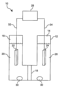
Another exemplary embodiment, illustrated in FIG. 8, pertains to the
production of
nanoparticles by a method where the first precursor is exposed to an electrode
reducing
agent reaction promoter. The system 10 includes a reaction vessel 12 having
first 14 and
second 16 compartments separated by an ion permeable barrier 18. A cadmium
solution is
prepared by first dissolving anhydrous cadmium acetate in TOP, and this
mixture is then
mixed with TOPO and TDPA. The resulting mixture 20 is placed in compartment
16. An
electrochemical system reaction promoter, such as a platinum cathode 22 is
then immersed
in mixture 20. A platinum anode 24 would be set up immersed in a solution
containing an
oxidizable component (e.g., iodide) 26 in compartment 14 and an appropriate
power
supply 28 would be set up outside the reaction vessel, and in electrical
communication
with cathode 22 and anode 24 through leads 32 and 34, respectively.
Optionally, magnetic
stirring bars 30 can be placed in compartments 14 and 16. The mixture is
heated to a
temperature sufficiently high to insure formation of nanoparticles when the
second
precursor is added at an appropriate potential. A selenium solution,
previously prepared
by dissolving Se in TOP, is then injected into the cadmium solution 20 in
compartment 16.
A negative potential is applied at the cathode 22 to induce formation of
nanoparticles.
The reaction is stopped by cooling, and/or by removing the potential.
VII. METHODS OF FORMINGNANOPARTICLE SHELLS
The surface of the semiconductor nanoparticle can be modified to enhance the
efficiency of the emissions, by adding an inorganic layer or shell. The
overcoating layer
CA 02460674 2004-03-16
WO 03/030227 PCT/US02/31436
-22-
can be particularly useful since surface defects on the semiconductor
nanoparticle can
result in traps for electrons or holes that degrade the electrical and optical
properties of the
nanoparticle. An insulating layer at the surface of the nanoparticle provides
an atomically
abrupt jump in the chemical potential at the interface that eliminates energy
states that can
serve as traps for the electrons and holes. This results in higher efficiency
in the
luminescent process.
The nanoparticles produced by the methods described herein can be provided
with
a shell by any method known in the art. See for example, Dabbousi et al., .I.
Phys. Chem.
B 101:9463 (1997), Hines et al., J. Phys. Chem. 100:468-471 (1996), Peng et
al., J. Am.
Chem. Soc. 119:7019-7029 (1997), and I~uno et al., J. Phys. Chem. 106:9869
(1997). In
addition, the nanoparticles of the invention can also be provided with a shell
using the
reaction promoter-based method described herein. In fact, the reaction
promoter-based
methods of the invention find utility in nanoparticle shell procedures for
both nanoparticle
cores produced by the methods described herein as well as nanoparticle cores
produced by
other methods.
The shell can have a thickness within the range of about 1-100 nm, and is
preferably within the range of about 2-10 nm thick.
Suitable materials for the inorganic shell layer include semiconductor
materials
having a higher bandgap energy than the semiconductor nanoparticle core. In
addition to
?0 having a bandgap energy greater than the core, suitable materials for the
shell should have
good conduction and valence band offset with respect to the core. Thus, the
conduction
band is desirably higher and the valence band is desirably lower than those of
the core.
For a semiconductor nanoparticle core that emits energy in the visible (e.g.,
CdS, CdSe,
CdTe, ZnSe, ZnTe, GaP, GaAs) or near IR (e.g., InP, InAs, InSb, PbS, PbSe)
range,
'S materials that have a bandgap energy in the ultraviolet regions may be
used. Exemplary
materials include ZnS, GaN, and magnesium chalcogenides, e.g., MgS, MgSe, and
MgTe.
For a semiconductor nanoparticle core that emits in the near IR range,
materials having a
bandgap energy in~the visible range, such as CdS or CdSe, may also be used.
In addition, a passivation layer of the desired thickness can also be easily
.0 introduced onto semiconductor nanoparticles of the invention by introducing
appropriate
solvents and/or surfactants during the nanoparticle manufacture. For example,
CA 02460674 2004-03-16
WO 03/030227 PCT/US02/31436
- 23 -
semiconductive nanoparticles, as manufactured by the methods described herein,
can be
provided with a water-insoluble organic overcoat that has an affinity for the
semiconductive core material. This coating will typically be a passivating
layer produced
by one or more coordinating solvents as described above, e.g.,
hexyldecylamine, TOPO,
TOP, TBP, and so forth; or produced by one or more hydrophobic surfactants
such as, by
way of example, octanethiol, dodecanethiol, dodecylamine, tetraoctylammonium
bromide,
and so forth, as well as combinations thereof.
Further, as noted above, the nanoparticle shell can be produced by the
reaction
promoter-based methods of the invention. Accordingly, an embodiment of the
invention is
a method of producing a nanoparticle shell comprising: producing nanoparticles
using
steps (a) though (e) described above in Section VI; (a') mixing the
nanoparticles with at
least one coordinating solvent to form a third mixture; (b') heating the third
mixture to a
temperature that is sufficiently high to form a shell on the nanoparticles
when third and
fourth precursors are added; (c') introducing third and fourth precursors into
the third
mixture to form a fourth mixture thereby resulting in the formation of shells
on a plurality
of nanoparticles; and (d') cooling the third mixture to stop further growth of
the shell;
wherein the method further comprises exposing the third or fourth mixture to a
reaction
promoter selected from the group consisting of oxygen and a reducing agent.
Exposure to
the reaction promoter can occur at several stages during the shell production
method. For
example, the third mixture can be exposed to the reaction promoter after step
(a'), the
heated third mixture can be exposed to the reaction promoter after step (b'),
or the fourth
mixture can be exposed to the reaction promoter in step (c'). In a preferred
embodiment,
the third mixture is exposed to the reaction promoter after step (a').
As noted above, the semiconductor materials used in the shell preferably have
a
higher bandgap energy than the semiconductor nanoparticle core. Therefore, the
precursors used in steps (d) ("first" and "second" precursors) are preferably
different than
the precursors used in step (c') ("third" and "fourth" precursors). However,
the ligand (if
used) and coordinating solvents used in step (a') can be the same or different
from those
used in step (a).
In addition, the shell producing method of the invention also finds utility
for
nanoparticle cores produced by any method known in the art. Accordingly,
another
CA 02460674 2004-03-16
WO 03/030227 PCT/US02/31436
-24-
embodiment of the invention is a method of producing nanoparticle shells
comprising (a)
mixing nanoparticles with at least one coordinating solvent to form a first
mixture; (b)
heating the first mixture to a temperature that is sufficiently high to form a
shell on the
nanoparticles when first and second precursors are added; (c) introducing
first and second
precursors into the first mixture to form a second mixture thereby resulting
in the
formation of shells on a plurality of nanoparticles; and (d) cooling the
second mixture to
stop further growth of the shell; wherein the method further comprises
exposing the first or
second mixture to a reaction promoter selected from the group consisting of
oxygen and a
reducing agent. As noted above, exposure to the reaction promoter can occur at
several
l0 stages during the shell production method. For example, the first mixture
can be exposed
to the reaction promoter after step (a), the heated first mixture can be
exposed to the
reaction promoter after step (b), or the second mixture can be exposed to the
reaction
promoter in step (c). In a preferred embodiment, the first mixture is exposed
to the
reaction promoter after step (a).
VIII. SHELL ADDITIVES
The methods of the invention also find utility in nanoparticles as described
in
commonly owned, co-pending U.S. Patent Application No. 10/19,635, filed on
July 17,
2002, by Treadway et al., the disclosure of which in incorporated herein in
its entirety, for
both nanoparticles produced by the methods described herein or produced by
state of the
art methods.
Accordingly, an embodiment of the invention is a method of producing
nanoparticles comprising: producing nanoparticles using steps (a) though (e)
described
above or produced by any state of the art method; and (a') mixing the
nanoparticles with an
additive or additive precursor, an optional ligand and at least one
coordinating solvent to
form a third mixture; (b') exposing the third mixture to a reaction promoter
selected from
the group consisting of oxygen and a reducing agent; (c') heating the third
mixture to a
temperature that is sufficiently high to form a shell on the nanoparticles
when third and
fourth precursors are added; (d') introducing third and fourth precursors into
the third
mixture to form a fourth mixture thereby resulting in the formation of shells
on a plurality
of nanoparticles; and (e') cooling the fourth mixture to stop further growth
of the shell.
CA 02460674 2004-03-16
WO 03/030227 PCT/US02/31436
- 25 -
The additive or additive precursor can be any inorganic material that is
suitable for use in
the manufacture of semiconductor nanoparticles, such as those described
herein.
The shell-forming aspect of the inventions as described herein is illustrated
as
follows. InAs nanoparticles are produced by the methods described herein or by
methods
that are well known in the art. The nanoparticles are then mixed with an
additive
precursor (e.g., a source of In+3), an optional ligand and at least one
coordinating solvent to
form a mixture. The mixture is then exposed to a reaction promoter such as
DPP. The
mixture is heated to the appropriate temperature and first and second
precursors (e.g., a
source of Cd2+ and Se°) are introduced by injection into the mixture to
form a CdSe shell.
The mixture is then cooled to stop further growth of the shell. Since the Cd+2
must be
reduced to Cd° and the In+3 must be reduced to In°, at least 5
equivalents of the reaction
promoter would be optimal, depending, at least in part, on the relative
amounts of additive
(In+3) and first precursor (Cd2+).
1 S IX. METHODS OF OVERCOATING NANOPARTICLES
The nanoparticles of the invention may also be provided with an organic
coating.
Suitable organic materials include agaroses; cellulose; epoxies; and polymers
such as
polyacrylamide, polyacrylate, poly-diacetylene, polyether, polyethylene,
polyimidazole,
polyimide, polypeptides, polyphosphate, polyphenylene-vinylene, polypyrrole,
ZO polysaccharide, polystyrene, polysulfone, polythiophene, and polyvinyl. The
coating can
also be a material such as silica glass; silica gel; siloxane; and the like.
Therefore, the invention also encompasses a method of producing coated
nanoparticles comprising: producing nanoparticles, wherein the nanoparticle
core and/or
shell is produced by the methods of the invention; and mixing the
nanoparticles with an
?5 organic compound having affinity for the nanoparticle surface, whereby the
organic
compound displaces the coordinating solvent to form a coating on the
nanoparticle
surface. The organic coating step is preferably conducted at a temperature
within the
range of about 50 to 350°C, preferably within the range of about 150 to
250°C. The actual
temperature range of the coating step may vary, dependent upon the relative
stability of the
SO reaction promoter, precursors, ligands, coordinating solvents and overlayer
composition.
CA 02460674 2004-03-16
WO 03/030227 PCT/US02/31436
-26-
ExAMPLES
The practice of the present invention will employ, unless otherwise indicated,
conventional techniques of synthetic inorganic, organic chemistry, chemical
engineering,
and the like, which are within the skill of the art. Such techniques are
explained fully in
S the literature. See, for example, Kirk-Othmer's Encyclopedia of Chemical
Technology;
House's Modern Synthetic Reactions; and the Chemical Engineer's Handbook.
The following examples are put forth so as to provide those of ordinary skill
in the
art with a complete disclosure and description of how to make and use the
compositions
and methods of the invention. Efforts have been made to ensure accuracy with
respect to
numbers (e.g., amounts, temperature, etc.) but some experimental error and
deviations
should, of course, be allowed for. Unless indicated otherwise, parts are parts
by weight,
temperature is degrees centigrade and pressure is at or near atmospheric. All
components
were obtained commercially unless otherwise indicated.
1 S MATERIALS
In all the examples which follow, materials were obtained as follows, unless
otherwise indicated: tri-n-octylphosphine oxide (TOPO, >97% purity) was from
Fluka; tri-
n-octylphosphine (TOP, 90% purity) was from Alfa Aesar; selenium (99.99%
purity) and
dicyclohexylphosphine (98% purity) were from Strem; diphenylphosphine (DPP,
>90%
~0 purity, 99.9% by certificate of analysis) and hydroquinone (+99% purity)
were obtained
from Aldrich; and anhydrous cadmium acetate (99% purity) was from Prochem.
Tetradecylphosphonic acid (TDPA, 98% purity) was either obtained from Alfa or
synthesized using methods well known in the art (I~osolapoff, et al., J. Am.
Chem. Soc.
67:1180-1182 (1945). All reagents were used as received without further
purification.
?S
EXAMPLE 1
REACTIONS WITH PHOSPHINES ADDED
TOPO (6.0 g) and TDPA (0.S77 g) were combined in a three-neck round bottom
flask equipped with a stir bar, a thermocouple attached to a temperature
controller unit,
30 and a condenser connected to a nitrogen/vacuum manifold. The third neck was
sealed
with a septum. The atmosphere inside the reactor was evacuated once and
refilled with dry
CA 02460674 2004-03-16
WO 03/030227 PCT/US02/31436
-27-
nitrogen. Inside an inert atmosphere glove box, a cadmium precursor solution
(0.S m) was
prepared by combining cadmium acetate (21.6 g) and TOP (166 g) and allowing
the
mixture to stir for ~24 hours until fully dissolved. An aliquot (2.03 g) of
this solution was
diluted with TOP (3.6 mL) and injected via syringe into the reaction vessel. A
16-gauge
S needle was inserted into the septum of the reaction vessel so that the
vessel could be
continuously flushed with nitrogen for approximately 10 min as the reaction
was heated to
2S0°C. The needle was removed and heating continued to 260°C.
Heating was continued
at 260-270°C for 10 min. The reaction was cooled to 100°C and
vacuum degassed for 30
min before the vessel was returned to a nitrogen atmosphere. An amount of
phosphine
(table below) was added as one portion via syringe. The selenium stock
solution was
prepared by combining selenium (3.2 g) and TOP (66.0 g) inside the inert
atmosphere
glove box. The temperature controller attached to the reaction vessel was set
to 290°C and
at the 270°C mark, selenium stock (1.4 mL) was rapidly injected to
induce nanoparticle
formation. Small aliquots were removed periodically from the stirring reaction
and diluted
1 S in hexane so that emission spectra could be obtained as a function of
reaction time.
TABLE 1
Additive Proportion Amount
Dicyclohexylphosphine 1 x 41 S p,L
?0 Diphenylphosphine 0.25 x 90 ~,L
Diphenylphosphine 1 x 360 p,L
Diphenylphosphine S x 1.8 mL
Diphenylphosphine 10 x 3.6 mL
~S FXAMPT.F 7.
REACTIONS WITH HYDROQUINONE ADDED
These reactions were carried out as described in Example 1, with the following
modifications. No phosphine-based reaction promoter was added to these
reactions.
Instead hydroquinone (0.226 g) was combined with the TOPO and TDPA solids
prior to
.0 the nitrogen flush of the reactor in the first step.
CA 02460674 2004-03-16
WO 03/030227 PCT/US02/31436
-28-
EXAMPLE 3
REACTIONS DEMONSTRATING THE USE OF AIR AS A REAGENT
In this example, TOP was obtained from Fluka and used as received. A solution
of
Se was prepared by dissolving Se (3.16 g) in TOP (33.2 g) (TOPSe). Separately,
a
cadmium precursor stock solution was prepared by dissolving anhydrous cadmium
acetate
(6.15 g) in TOP to a final volume of 40 mL (cadmium stock solution). In each
of three
round bottom flasks, TOPO (5.0 g) was combined with cadmium stock solution
(1.4 mL),
TDPA (0.52 g), and TOP (1.1 mL) and heated to 250°C while continuously
flushing the
vessel with NZ. Once the temperature reached 250°C, the nitrogen flush
was halted and the
0 temperature was increased to 270°C. This temperature was maintained
for 20 min and the
solutions were cooled to 100°C. Using a large-bore needle, dry air was
directed into each
of two flasks at a rate of 200 ml/min for a duration of 1 minute or 10
minutes. A third
flask received dry nitrogen for 10 minutes at the same flow rate. Stirring of
the solution
was maintained throughout. After the exposure period, the flasks were
evacuated and
L 5 refilled with dry nitrogen. This was repeated once. The flasks were then
reheated to
270°C and an aliquot of the previously prepared TOPSe solution (1.4 mL)
was rapidly
injected. The reaction temperature was maintained at 270°C while small
samples were
periodically removed. Reactions were stopped by cooling to 100°C.
The time period between injection of TOPSe and the first appearance of color
was
?0 noted. This "induction time" is related to the reactivity of the solution.
Yields of the
reactions were determined by the peak band-edge absorbance, normalized for
particle size.
Results are presented in Table 2 and FIG. 6.
TABLE 2
a5 Condition, time Induction time, Relative particle Peak absorbance
of exposure to air seconds yield wavelength, nm
minutes dry nitrogen 45 1 582
1 minute dry air 6 2.8 561
10 minutes dry air 2 18.7 510
CA 02460674 2004-03-16
WO 03/030227 PCT/US02/31436
-29-
This data indicates that exposure to air resulted in a higher yield than the
control
conditions, and that the yield is modulated by the length of the air exposure
period.
Further, it can be seen that the time course evolution of particle size and
particle size
distribution, is also controllable by the method of the invention. This shows
that the
reaction can be tuned to achieve a taxget size while still maintaining a high
yield and good
particle size uniformity.
EXAMPLE 4
Cadmium acetate/TOP stock and TOPSe were prepared as in Example 3. In a
l0 round bottom flask, 2.5 g TOPO was combined with 0.703 mL cadmium
acetate/TOP
stock, 0.26 g tetradecylphosphonic acid and 0.55 mL TOP and heated to
250°C while
sparging with N2. Once the temperature reached 250°C, sparging was
stopped, the
temperature was increased to 270°C and held at this temperature for 20
minutes. The
solution was cooled to 100°C. One neck of the flask was opened and dry
compressed air
t 5 was directed into the stirring solution for 10 minutes. After the exposure
period, the flask
was evacuated and refilled with dry nitrogen. This was repeated two more
times. The
flask was then reheated to 240°C and 0.7 mL of TOPSe was rapidly
injected. After 15
seconds, the reaction was stopped by injecting 5 mL TOP and removing the heat
source.
An aliquot was removed and measurement showed the band-edge absorbance peak at
448
,0 nm with the luminescence peak at 471 nm with 31 nm FWHM.
This data illustrates the ability to independently control the fundamental
aspects of
the crystal growth process, thereby enabling the high yield synthesis of very
small CdSe
nanoparticles.
2S EXAMPLE 5
REACTIONS MAKING USE OF PRE-AIR-TREATED REAGENTS
In this example, TOP was obtained from Fluka and used as received. The
cadmium precursor and TOPSe were prepaxed as in Example 3. In each of two
round
bottom flasks, TOPO (3.0 g) was combined with cadmium stock (0.76 mL), TDPA
(0.282
30 g), and TOP (1.24 mL) and heated to 250°C while continuously
flushing with dry nitrogen.
Once the temperature reached 250°C, nitrogen-flushing was halted, and
the temperature
CA 02460674 2004-03-16
WO 03/030227 PCT/US02/31436
-30-
was increased to 270°C and held at this temperature. In a separate
nitrogen-blanketed
flask, TOP (~5 mL) was heated to 100°C. Once the temperature reached
100°C, the flask
was opened to air and held at 100°C, while stirring, for 50 minutes.
The flask was then
closed and evacuated, followed by refilling with nitrogen. This purgelrefill
was repeated
one more time. To one flask containing the cadmium solution (at 270°C)
was added air-
exposed TOP (1 mL). To the other cadmium-containing flask (at 270°C)
was added
unexposed TOP (1 mL). Using a syringe, an aliquot of TOPSe stock (0.71 mL) was
rapidly injected into each flask. The temperature was maintained at
270°C while small
samples were periodically removed. Reactions were stopped by cooling to
100°C.
The time period between injection of TOPSe and the first appearance of color
was
noted. Yield of the reactions was determined by the peak band-edge absorbance,
normalized for particle size. Results are presented in Table 3 and FIG. 7.
This data indicates that exposure of TOP to air generates a material that can
be
added to a reaction mix, resulting in higher yield and with useful modulation
of particle
size and particle size distribution.
TABLE 3
Exposure Induction time, Relative particle Peak absorbance
time of TOP to air seconds yield wavelength, nm
None 18 1 583
50 minutes 4 2.875 579
It is to be understood that while the invention has been described in
conjunction
with the preferred specific embodiments thereof, that the foregoing
description as well as
the examples that follow, are intended to illustrate and not limit the scope
of the invention.
It should be understood by those skilled in the art that various changes may
be made and
equivalents may be substituted without departing from the scope of the
invention, and
further that other aspects, advantages and modifications will be apparent to
those skilled in
the art to which the invention pertains.