Note: Descriptions are shown in the official language in which they were submitted.
CA 02460699 2004-03-11
LEAK COLLECTION DEVICE
Description
This invention concerns a device for collecting leaked substances.
Technical Area
Various seals used to seal off items, particularly shaft openings, are already
known.
Radial shaft seal rings, axial face seals and so forth, for which there are
many applications, are
very common. All seals have in common that they are subject to wear and when
they lose their
sealing effectiveness, they must be replaced. Leakage must be prevented, since
in many
applications, it can cause great damage. There is thus a need to detect
unwanted leakage, whether
of liquid or of gas, in a timely manner so that the defective seal can be
replaced.
Background of the Invention
A leak collection device is known from DE 100 61 1. l l Al. This leak
collection device
includes a collector for storing the leaked substance and an optical sensor.
The sensor emits a
signal when the optical characteristics of the collector are altered when
covered with leaked
fluid.
The amount of leaked fluid necessary to set off the ;sensor alarm depends on
its spatial
position and alignment. Although the alignment of the sensor can be pre-
determined when the
seal system is assembled in a machine part, it can no longer be guaranteed
when the machine part
is assembled in a machine unit. The sensor emits a signal even when the amount
of substance
leaked is small, which can happen when, for example, a foreign body
temporarily passes through
the seal lip.
Summary of the Invention
The task of this invention is to further develop the already-known seal system
in such a
way that the sensor has the same sensitivity and will not detect temporary
leakage, whatever its
spatial alignment may be.
This problem is resolved through this invention with the characteristics of
Claim 1. The
remaining claims concern advantageous implementations of the invention.
CA 02460699 2004-03-11
Because the collector receiving the leaked substance: is absorbent and/or
swellable and
because the design of the collector makes it possible to delay detection, the
leakage is distributed
evenly over the collector and, when a leaked substance is collected, detection
is delayed,
regardless of how the sensor is installed.
Preferably, the collector is in the form of an absorbent round disk. The round
shape
allows optimal use of the available space.
In one advantageous implementation, the collector is centered in the leak
collection
device by means of a circular bulge running around it. This centering ensures
that the collector
contacts the entire circumference of the machine element - for example, a
shaft - to be sealed off
and collects the leaked substance.
The collector can be made of a fleece material. Fleece materials are
inexpensive and easy
to use.
In one advantageous implementation, the sensor is i:rxed to a support plate.
Fixing the
sensor to a support plate makes it possible to position the sensor in a
specific place in the seal
system.
The collector and/or the support plate with the sensor can be installed in a
support ring.
By installing them in a support ring, the collector and/or the support plate
with the sensor can be
assembled as a unit, thus simplifying assembly.
In one advantageous implementation, the support plate is locked in a groove
located on
the side of the axial shank of the support ring facing the shaft. Being locked
in the groove
ensures that the support ring is securely fixed in a set position in the
support ring.
The sensor can be positioned at a distance from the collector by means of a
spacer.
Optical sensors such as reflection photoelectric beam systems must be located
at a minimum
distance from the collector being monitored as determined t>y function. This
minimum distance
is provided by the spacer.
In another advantageous implementation, the seal ring and the support ring
form an
interspace that serves to collect leaked substances. The interspace collects
temporary leakage,
such as when a foreign body passes through the seal gap. Collecting the leaked
substances in the
interspace delays the emission of a signal caused by the colle:etion of the
leaked substance by the
collector. Thus, excessive maintenance costs resulting from ~?remature seal
ring replacement and
machine down time can be avoided.
2
CA 02460699 2004-03-11
Preferably, there is an annular element made of an absorbent material in the
interspace.
This absorbent material allows the entire annular interspace to be used as a
collector, which
increases collection capacity. Absorption by the collector, 'which causes the
sensor to emit a
signal, can be further delayed compared to an interspace without an absorbent
material.
In another implementation, a round disk made of an absorbent material is
placed against
the seal ring on the side facing the environment, which is located before the
leak collection
device. The disk makes it possible to absorb temporary leakages. Signal
emission is again
delayed.
The seal ring can be inserted into the support ring. By inserting the seal
ring in a support
ring, the seal ring and the leak collection device can be assembled as a
subassembly in a unit.
In another implementation, the leak collection device is installed in a recess
located on
the outer circumference of the seal ring by means of the support ring. The
recess ensures that the
support ring is securely seated and that the leak collection device is
centered in the seal ring.
It is preferable that the elastomer coating of the support ring in the
direction of the
environment have at Least one seal lip that contacts the shaft, thus sealing
it off, or is located a
short distance from it. The seal lip protects the leak collection device
against dirt particles from
the environment.
In one implementation, the sensor detects optical changes in the collector.
Optical sensors
make it possible to take measurements without contact.
The sensor can be in the form of an infrared reflection photoelectric beam
system.
In another implementation, the sensor is in the form of a mechanical system
that detects
changes in collector volume.
In another implementation, leaks are sensed by mf;ans of changes in the
collector's
dielectric behaviour. In this implementation, the collector is installed
between two capacitor
plates, comprised of, for example, the seal ring support rings .and the leak
collection device, or of
coatings made of a conductive material on both sides of the collector. When a
leaked substance
is absorbed, the dielectric behaviour of the collector changes, which is
detected by the sensor
device. The capacitor plates can be the same size as the collector, or can
consist of one or more
smaller segments.
The sensor signal can be transferred without cables. In this implementation,
the cable
conduit and its seal in the housing are eliminated.
3
.. m ~_ x. ,uv .~ .... ._ ~ ~ _. _ __ . , ~_ ~ ~~~~ ~ n ,.. _ ____ _ ____ _
CA 02460699 2004-03-11
It is preferable that the sensor signal be carried by me;ans of a round or
flat ribbon cable.
Cable transmission is simple and inexpensive.
In one advantageous implementation, the flat ribbon cable is routed through a
cable
conduit that is lined with an elastomer. The elastomer ensures the tightness
of the cable conduit.
The elastomer of the cable conduit can be bound with the flat ribbon cable
with an
appropriate material.
The support ring preferably has an elastomer coating on its axial shank around
the outer
circumference. This elastomer coating seals the device statically in the
direction of the housing.
Brief Description of the Drawings
Implementation examples of the leak collection device are explained in greater
detail
below using figures 1 to 9. These show schematically:
Figure 1 a seal ring in longitudinal section;
Figure 2 a seal ring with an interspace for collecting le;eked substances;
Figure 3 a seal ring with an auxiliary absorbent disk for collecting leaked
substances;
Figure 4 a seal ring with a ring made of an absorbent material that is located
in the
interspace and has a spacer for positioning the sensor;
Figure 5 a seal ring with a ring made of an absorbent material in the
interspace;
Figure 6 a seal ring with a support ring and a disk for collecting leaked
substances;
Figure 7 a seal ring with a support ring and a disk for collecting leaked
substances;
Figure 8 a seal assembly with a disk for collecting leaked substances and a
sensor on the
outside; and
Figure 9 a seal assembly with a disk for collecting leaked substances and a
sensor on the
inside.
Description of the Preferred Embodiment
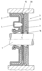
Figure 1 shows a seal assembly with a seal ring (2) - in this implementation,
a radial
shaft seal ring - and a leak collection device (3). The leak collection device
(3) includes a
metallic support ring (7) with an axial and a radial shank. ~.n elastomer
coating ( 11 ) is molded
onto both sides of the radial shank, which forms a seal lip (I6) to seal off
the shaft (1), which
contacts the shaft ( 1 ), thereby sealing it off.
4
CA 02460699 2004-03-11
The support ring is .fixed in a recess (15), located on the seal ring (2) on
the outer
circumference facing the housing (20). A collector (5) made of an absorbent
material serving to
collect leaked substances is installed between the seal ring (2) and the
elastomer coating (11) of
the support ring (?). The sensor {4) is installed in the elastomer coating of
the seal ring (2) in
such a way that the front of the sensor can contact the collector (5).
Figure 2 shows a seal assembly in which the axial shank of the support ring
(?) of the
leak collection device (3) is constructed longer so that an interspace (12) is
formed between the
seal ring (2) and the radial shank of the support ring (?), which serves to
collect leaked
substances. The sensor (4) is mounted on a support plate (6). The support
plate (6) is centered in
the axial shank of the support ring (?). The support plate (6) has holes
distributed around its
circumference which conduct leaked substances to the collector (5). The signal
emitted by the
sensor (4) is carried out by a flat ribbon cable (l?).
Figure 3 shows a seal assembly in which a disk (1)4 made of an absorbent
material is
fitted directly against a seal ring (2) on the side of the seal ring (2)
facing the interspace (12). The
disk (14) is located before the interspace and the collector (5) and serves to
absorb temporary
leakages. The collector (5) is centered by means of an annular ring (10) that
is formed by the
elastomer coating ( 11 ) of the radial shank of the support ring (?). The
support plate (6) to which
the sensor (4) is fixed is locked in a groove (8) located on the side of the
axial shank of the
support ring (?) facing the shaft ( 1 ). The signal from the sensor (4) is
carried out through a cable
conduit ( 18) by a flat ribbon cable ( 1 ?). The cable conduit ( 18) is made
of an elastomer material
and is bound with the flat ribbon cable ( 1 ?).
Figure 4 shows a seal assembly in which a ring (13) made of an absorbent
material is
installed in the interspace (12). The ring absorbs leaked substances that are
distributed over the
entire interspace by its absorbency. The sensor (4) is mounted on a support
plate (6) and is kept
at a fixed distance from the collector (5) by means of a spacer (9). The
elastomer coating (11) of
the radial shank of the support ring {?) forms two v-shaped seal lips facing
in the direction of the
machine element to be sealed off, which contact the shaft. The ring space thus
formed contains a
lubricant.
Figure 5 shows a seal assembly in which the seal ring (2) is installed in the
support ring
(?) of the leak collection device (3). This makes it possible i:o assemble the
seal ring (2) and the
CA 02460699 2004-03-11
leak collection device (3) as a unit. The axial shank of the support ring {7)
is covered completely
on the outer circumference ( 19} and partially on the inside ( 10) with an
elastomer coating. The
outer coating ( 19) ensures the static tightness of the seal assembly in
relation to the housing (20).
A groove (8) in which the carrier plate (6) is locked runs around the partial
coating ( 10) on the
inside of the support ring (7).
Figure 6 shows a seal assembly with a standard radial shaft seal ring (2) and
a leak
collection device (3). The collector 5, made of an absorbent fleece material,
lies on the shaft (1)
and serves both to collect leaked liquids and to protect the seal ring (2)
against contamination
from the environment. The sensor 4 is located on the side of the support ring
(7) facing the
environment. Signals are carried over the cable (17).
Figure 7 shows an implementation example of a seal assembly in accordance with
Figure
(6) where the sensor (4) is located in the interspace between the seal ring
(2) and the support ring
(7). In this example, the sensor is protected against mechanical damage from
the environment.
Figure 8 shows a seal assembly with a seal ring (2) and an auxiliary seal (21
) that is made
up of a dust lip (22) and a support ring (23). The axial flange {24) of the
support ring (23) of the
auxiliary seal (21 ) is inserted into the elastomer coating (25;1 of the axial
flange (26) of the seal
(2), thereby creating a seal. There is a collector (S) in the interspace
between the seal ring (2) and
the support ring (23). The sensor (4 )is located on the side of the seal ring
(2 )facing the
environment.
Figure 9 shows a seal assembly in accordance with Figure 8 in which the sensor
(4) is
located in the interspace between the seal ring (2) and the support ring (23).
6