Language selection

Search

Patent 2460978 Summary

Third-party information liability

Some of the information on this Web page has been provided by external sources. The Government of Canada is not responsible for the accuracy, reliability or currency of the information supplied by external sources. Users wishing to rely upon this information should consult directly with the source of the information. Content provided by external sources is not subject to official languages, privacy and accessibility requirements.

Claims and Abstract availability

Any discrepancies in the text and image of the Claims and Abstract are due to differing posting times. Text of the Claims and Abstract are posted:

  • At the time the application is open to public inspection;
  • At the time of issue of the patent (grant).
(12) Patent: (11) CA 2460978
(54) English Title: METHOD OF REDUCING TORQUE SHOCK ON A TRANSMISSION
(54) French Title: METHODE DE REDUCTION DU CHOC DE COUPLE D'UNE TRANSMISSION
Status: Granted
Bibliographic Data
(51) International Patent Classification (IPC):
  • F16D 3/12 (2006.01)
  • F16D 3/28 (2006.01)
(72) Inventors :
  • JURANKO, ANTON (Canada)
(73) Owners :
  • JURANKO, ANTON (Canada)
(71) Applicants :
  • JURANKO, ANTON (Canada)
(74) Agent:
(74) Associate agent:
(45) Issued: 2011-08-02
(22) Filed Date: 2004-03-19
(41) Open to Public Inspection: 2005-06-23
Examination requested: 2009-01-06
Availability of licence: N/A
(25) Language of filing: English

Patent Cooperation Treaty (PCT): No

(30) Application Priority Data:
Application No. Country/Territory Date
10/743,078 United States of America 2003-12-23

Abstracts

English Abstract


Torque shock peaks when an automatic transmission shifts gears. A
method of reducing this torque shock to prolong the life of engines,
transmissions
and the entire power train in vehicles and heavy equipment most generally
comprises
the steps of transmitting rotational power through a torque shock absorber
having a
generally cylindrical housing adapted for attachment to a drive on a flywheel

end and to a driven shaft on the other flywheel end. Thereby peak torque loads

transmitted through the torque shock absorber are reduced. In a preferred
embodiment of the invention the torque shock absorber comprises a housing
having
peripheral spaced bolts there through. Bolt openings therein are surrounded by
a
rubber bushing in the housing so that when the torque shock absorber is bolted
to a
flywheel peak torque loads are absorbed by the rubber bushings. The most

preferred placement for the torque shock absorber in the power train is
between an
engine and remotely mounted transmission.

This torque shock absorber is not "a coupling". It is a torque shock absorber
invented with the intention to improve the performance or replace the rubber
element
drive shaft "Spicer" #908464.

That is why this torque shock absorber is a totally new invention.


French Abstract

Un choc de couple atteint un sommet lorsqu'une transmission automatique change de vitesse. Une méthode de réduire le choc de couple afin de prolonger la vie des moteurs, des transmissions et du groupe motopropulseur de véhicules et d'équipement lourd comprend généralement les étapes suivantes : la transmission d'énergie rotationnelle au moyen d'un amortisseur de choc de couple comprenant généralement un logement cylindrique adapté pour être fixé à un dispositif d'entraînement sur une extrémité d'un volant-moteur et à un arbre récepteur sur l'autre extrémité du volant-moteur. Par conséquent, les charges de couple à leur sommet transmises par l'amortisseur de choc de couple sont réduites. Dans une réalisation préférée de l'invention, l'amortisseur de choc de couple comprend un logement doté de boulons périphériques espacés et traversants. Des ouvertures de boulon sont entourées d'une bague de caoutchouc dans le logement de façon que lorsque l'amortisseur de choc de couple est boulonné au volant-moteur, les charges de torque au somment sont absorbées par les bagues de caoutchouc. Le placement préféré pour l'amortisseur de choc de couple dans le groupe motopropulseur est entre un moteur et une transmission montée à distance. Cet amortisseur de choc de couple n'est pas « un couplage ». Il s'agit d'un amortisseur de choc de couple inventé dans l'intention d'améliorer la performance ou de remplacer l'arbre d'entraînement de l'élément en caoutchouc de « Spicer » numéro 908464, c'est pourquoi le présent amortisseur de choc de couple est une invention totalement nouvelle.

Claims

Note: Claims are shown in the official language in which they were submitted.


I CLAIM


1) A method of reducing peak torque loads caused by automatic gear shifting
comprising the steps of: transmitting rotational power through a torque shock
absorber having
a generally cylindrical housing adapted for attachment to a drive shaft on one
cylindrical end
and to a driven shaft on the other cylindrical end; so that peak torque loads
transmitted

through the torque shock absorber are reduced; wherein the torque shock
absorber includes
peripheral spaced bolts through openings in the housing and wherein said bolt
opening are
surrounded by a rubber bushing in the housing so that, when the bolts are
fastened to a flange
of the drive shaft, torque loads are absorbed by the rubber bushings; wherein
each bolt also
extends through a centering flange which engages the torque absorber housing
opposite the
drive shaft flange to limit axial movement of the torque absorber housing
relative the flange.


2) A method as in claim 1 wherein the rubber bushings surround a steel bolt
sleeve.

3) A method as in claim 2 wherein the rubber bushings are surrounded by a
cylindrical steel ring to facilitate positioning with in the housing.


4) A method as in claim 3 wherein the driveshaft and drive flange comprises
fly
wheel turned by a crankshaft on an internal combustion engine.


5) A method as in claim 4 where the drive shaft is adapted to be driven by a
driven
flange bolted to an inner center portion of the driven end of the generally
cylindrical torque
shock absorber.


6) A method as in 5 where in the driven shaft inputs power to an automatic
transmission.

Description

Note: Descriptions are shown in the official language in which they were submitted.


CA 02460978 2010-07-29

CA 02460978 2004-03-19
METHOD OF REDUCING TORQUE SHOCK
ON A TRANSMISSION

FIELD OF THE INVENTION

This invention relates to torque shock experienced between an engine and an
Automatic transmission when gears are shifted. More particularly this
invention relates to a
method off reducing this torque shock to prolong the life of engines,
transmissions, and the
entire power train in vehicles and heavy equipment.

This torque shock absorber is not "a coupling". It is a torque shock absorber
invented with the
intention to improve the performance or replace the rubber element drive shaft
"Spicer" #908464.
That is why this torque shock absorber is a totally new invention.

BACKGROUND OF THE INVENTION

Torque shock between power source and remotely mounted automatic
transmissions has long been, and continues to be a problem. Torque shock is
not only hard
on automatic transmissions, but on the crank shaft of engines, and the entire
drive train in
vehicles. Particularly on large trucks, and on heavy equipment having
automatic

transmissions, fast, forceful, and sudden contact between shifting gears
roughly jerks the
entire vehicle. High RPM shifts, either up or down, generates substantial
torque shock. This
torque shock results in a premature failure of engines, transmissions, drive
shafts, and
differentials. To correct the problem of torque shock, a torque shock
absorbing apparatus
that decreases the peak torque shock when gears are automatically shifted, is
needed.


CA 02460978 2010-07-29
CA 02460978 2004-03-19

One aspect of this invention provides for a method of reducing this torque
shock to
prolong the life of engines, transmissions, and the entire power train in
vehicles and heavy
equipment most generally comprises the steps of transmitting rotational power
through a

torque shock absorber having a generally cylindrical housing adapted for
attachment to a
drive on one cylindrical end and to a driven shaft on the other cylindrical
end. Thereby peak
torque loads transmitted through the torque shock absorber are reduced.

In a preferred aspect of this invention a preferred embodiment provides for
the
torque shock absorber comprising a housing having peripheral spaced bolts
there through.
Bolt openings therein are surrounded by a rubber bushing in the housing so
that when the
torque shock absorber is bolted to a flywheel, peak torque loads are absorbed
by the
rubber bushings. The most preferred placement for the torque shock absorber in
the power
train is between an engine and a remotely mounted automatic transmission.

Various other objects, advantages and features of this invention will become
apparent to those skilled in the art from the following description in
conjunction with the
accompanying drawings.


CA 02460978 2010-07-29
CA 02460978 2004-03-19

The inventor has determined that the position for the torque shock absorber is
directly on the engine or power source, before the automatic transmission.
When installed,
the torque shock absorber absorbs torque buildup during gear shifting. Drive
shaft vibrations
are eliminated. The torque shock absorber not only promotes smoother shifting
of gears, and
a smoother acceleration of the vehicle, but most importantly it reduces
fatigue and wear on
gears, bearings, and shafts within the transmission, as well as within all
components within
the entire remainder of the drive train. Peak torque and wear, and all of the
resulting fatigue
and failure of gears, shafts, bearings, universal joints, all along the entire
drive train can be
substantially reduced. While a torque shock absorber can compliment small
vehicles having
small engines and power transmission, the torque shock absorber has most
immediate

application on relatively large vehicles having large engines which transmit
substantial
power.

OBJECTS OF THE INVENTION

It is an object of this invention to disclose a method of substantially
reducing
maintenance, and extending the life of engines, automatic transmissions, and
all other
components in the drive train of a vehicle. It is an object of this invention
to disclose a
method of reducing peak torque caused by both up and down shifting of gears.
It is yet a
further object of this invention to disclose a method of producing smoother
acceleration and
deceleration of a vehicle.


CA 02460978 2010-07-29

CA 02460978 2004-03-19
FIGURES OF THE INVENTION

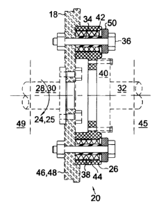
Figure 1 is a cross sectional view of a torque shock absorber mounted on a
flywheel
transmitting power to a drive shaft.

Figure 2 is a front view of the torque shock absorber shown in figure 1.

The following is a discussion and description of the preferred specific
embodiments
of this invention, such being made with reference to the drawings, wherein the
same
reference numerals are used to indicate the same or similar parts and/or
structure. It should
be noted that such discussion and description is not meant to unduly limit the
scope of the
invention.

DESCRIPTION OF THE INVENTION

Turning now to the drawings and more particularly to figure 1 we have a
perspective view of a cross sectional view of a torque shock absorber 20
mounted on a
flywheel 18 transmitting power to a drive shaft 32. Most generally a method of
reducing
peak torque loads 25 caused by automatic gear shifting comprises the steps of.
transmitting
rotational power 24 through a torque shock absorber 20, having a generally
cylindrical
housing 26 adapted for attachment to a crankshaft 28 on one cylindrical end,
and to a drive
shaft 32 on the other cylindrical end. Thereby peak torque loads 25
transmitted through the
torque shock absorber 20 are reduced.


CA 02460978 2010-11-23

The torque shock absorber 20 comprises a housing 26 having peripheral spaced
bolt
openings 34 and having bolts 36 there through. Said bolt openings 34 are
surrounded by a
rubber bushing 38 in the housing 26 so that when the torque shock absorber 20
is bolted to a
driven flange 40 peak torque loads 25 are absorbed by the rubber bushings 38.
Within this
specification rubber is defined to include a resilient plastic.

In the most preferred embodiment of the invention the rubber bushings 38
surround
a steel bolt sleeve 42. The rubber bushings 38 are surrounded by a cylindrical
steel ring 44 to
facilitate positioning them within the housing 26. The rubber bushings are
bonded between
the steel bolt sleeve 42 and the cylindrical steel ring 44. A centering
flanges 50 to axially
secure the housing 26 to a drive flange 46 of the drive shaft 28. In the most
preferred
embodiment of the invention the drive shaft 28 and drive flange 46 comprise a
flywheel 48
turned by a crankshaft 30 on an internal combustion engine 49. The driven
shaft 32 is
adapted to be driven by a driven flange 40 bolted to an inner central portion
of the driven end
of the generally cylindrical torque shock absorber 20. The driven shaft 32
inputs power to an
automatic transmission 45.

While the invention has been described with preferred specific embodiments
thereof, it will be understood that this description is intended to illustrate
and not to limit the
scope of the invention, which is defined by the following claims.

Representative Drawing
A single figure which represents the drawing illustrating the invention.
Administrative Status

For a clearer understanding of the status of the application/patent presented on this page, the site Disclaimer , as well as the definitions for Patent , Administrative Status , Maintenance Fee  and Payment History  should be consulted.

Administrative Status

Title Date
Forecasted Issue Date 2011-08-02
(22) Filed 2004-03-19
(41) Open to Public Inspection 2005-06-23
Examination Requested 2009-01-06
(45) Issued 2011-08-02

Abandonment History

There is no abandonment history.

Payment History

Fee Type Anniversary Year Due Date Amount Paid Paid Date
Application Fee $200.00 2004-03-19
Maintenance Fee - Application - New Act 2 2006-03-20 $50.00 2005-11-22
Maintenance Fee - Application - New Act 3 2007-03-19 $50.00 2005-11-22
Maintenance Fee - Application - New Act 4 2008-03-19 $50.00 2005-11-22
Request for Examination $400.00 2009-01-06
Maintenance Fee - Application - New Act 5 2009-03-19 $100.00 2009-01-29
Maintenance Fee - Application - New Act 6 2010-03-19 $100.00 2010-01-20
Maintenance Fee - Application - New Act 7 2011-03-21 $100.00 2011-02-01
Final Fee $150.00 2011-05-13
Maintenance Fee - Patent - New Act 8 2012-03-19 $100.00 2012-02-13
Maintenance Fee - Patent - New Act 9 2013-03-19 $100.00 2013-03-11
Maintenance Fee - Patent - New Act 10 2014-03-19 $125.00 2014-02-12
Maintenance Fee - Patent - New Act 11 2015-03-19 $125.00 2015-02-23
Maintenance Fee - Patent - New Act 12 2016-03-21 $125.00 2016-02-22
Maintenance Fee - Patent - New Act 13 2017-03-20 $125.00 2017-03-06
Maintenance Fee - Patent - New Act 14 2018-03-19 $125.00 2018-02-23
Maintenance Fee - Patent - New Act 15 2019-03-19 $225.00 2019-02-28
Maintenance Fee - Patent - New Act 16 2020-08-31 $225.00 2020-11-13
Late Fee for failure to pay new-style Patent Maintenance Fee 2020-11-13 $150.00 2020-11-13
Maintenance Fee - Patent - New Act 17 2021-03-19 $229.50 2021-06-04
Late Fee for failure to pay new-style Patent Maintenance Fee 2021-06-04 $150.00 2021-06-04
Maintenance Fee - Patent - New Act 18 2022-03-21 $229.04 2022-05-27
Late Fee for failure to pay new-style Patent Maintenance Fee 2022-05-27 $150.00 2022-05-27
Maintenance Fee - Patent - New Act 19 2023-03-20 $236.83 2023-07-07
Late Fee for failure to pay new-style Patent Maintenance Fee 2023-07-07 $150.00 2023-07-07
Owners on Record

Note: Records showing the ownership history in alphabetical order.

Current Owners on Record
JURANKO, ANTON
Past Owners on Record
None
Past Owners that do not appear in the "Owners on Record" listing will appear in other documentation within the application.
Documents

To view selected files, please enter reCAPTCHA code :


To view images, click a link in the Document Description column. To download the documents, select one or more checkboxes in the first column and then click the "Download Selected in PDF format (Zip Archive)" or the "Download Selected as Single PDF" button.

List of published and non-published patent-specific documents on the CPD .

If you have any difficulty accessing content, you can call the Client Service Centre at 1-866-997-1936 or send them an e-mail at CIPO Client Service Centre.


Document
Description 
Date
(yyyy-mm-dd) 
Number of pages   Size of Image (KB) 
Maintenance Fee + Late Fee 2020-11-13 1 56
Abstract 2004-03-19 1 27
Description 2004-03-19 5 169
Claims 2004-03-19 2 39
Drawings 2004-03-19 1 33
Representative Drawing 2004-05-04 1 10
Maintenance Fee Payment 2021-06-04 1 70
Maintenance Fee Payment 2022-05-27 1 51
Claims 2010-02-16 1 30
Cover Page 2005-06-14 1 43
Abstract 2010-07-29 1 27
Description 2010-07-29 5 141
Claims 2010-07-29 2 36
Description 2010-11-23 5 141
Claims 2010-11-23 1 30
Cover Page 2011-06-27 2 52
Correspondence 2004-04-19 1 19
Assignment 2004-03-19 3 73
Prosecution-Amendment 2010-02-16 2 51
Prosecution-Amendment 2009-04-02 2 56
Prosecution-Amendment 2009-01-06 1 25
Maintenance Fee Payment 2019-02-28 1 51
Fees 2005-11-22 1 50
Maintenance Fee Payment 2018-02-23 1 100
Fees 2009-01-06 1 46
Fees 2009-01-29 1 52
Prosecution-Amendment 2009-07-22 1 7
Prosecution-Amendment 2009-08-28 1 20
Correspondence 2010-02-01 1 18
Fees 2010-01-20 1 48
Prosecution-Amendment 2010-07-29 9 223
Prosecution-Amendment 2010-10-29 3 141
Prosecution-Amendment 2010-11-23 3 81
Fees 2011-02-01 1 103
Correspondence 2011-05-13 2 93
Fees 2012-02-13 1 205
Fees 2013-03-11 1 144
Fees 2014-02-12 1 120
Fees 2015-02-23 1 124
Maintenance Fee Payment 2016-02-22 1 119
Maintenance Fee Payment 2017-03-06 1 141
Maintenance Fee Payment 2023-05-29 1 38
Office Letter 2023-06-16 2 214
Maintenance Fee + Late Fee 2023-07-07 1 58