Note: Descriptions are shown in the official language in which they were submitted.
CA 02461114 2004-03-15
REMOTE RESTART OF FAILED TRAIN ON-BOARD CONTROLLER
BACKGROUND OF THE INVENTION
[01] Modern guideway transportation systems typically utilize Automatic Train
Control
Systems (ATCS) that feed various data to automatic control systems on-board
the trains.
Data is provided to controllers located on-board the trains and includes both
direct control
data used to control the actions of the respective trains and communication
data used to
communicate system-related information relative to the overall transportation
system.
[02] At various times during the operation of the ATCS, the on-board
controller of a given
train might fail. For example, a failure of a controller might include an
event related to the
hardware or software of the system that prevents the on-board controller from
performing
Automatic Train Operation (ATO) or Automatic Train Protection (ATP) functions.
[03] The ATP functionality ensures safe train movement. For instance, ATP is
designed
into an ATC system to prevent rear-end, head-on, and sideswipe collisions due
to
conflicting train movements; passenger hazards due to unscheduled door
openings; and
damage or collisions caused by improper guideway switch movements/settings, or
trains,
exceeding the allowed civil limit, or commanded, speeds.
[04] ATO performs required non-vital functions such as speed regulation,
programmed
stopping, door control and performance level regulation. ATO commands are
always
subordinate to the ATP subsystem supervision. The ATO subsystem of the ATC
system is
primarily designed to provide regulation command of the train speed within the
limits
imposed by the ATP subsystem and to provide train movement within the
passenger ride
quality criteria as established by operating policy. Additionally, the ATO
subsystem
CA 02461114 2004-03-15
controls station dwell-time control, i.e., the amount of time any given train
is permitted to
stand idle at a station; on-board station arrival display control; and train
audio
announcement control.
[05] In most, if not all, conventional ATC systems, once a failure occurs with
respect to
the on-board controller, it is necessary to dispatch a maintenance crew to the
failed train to
reset the failed controller. Manual intervention of this nature requires a
significant amount
of time, including time to detect the failure, time for the maintenance crew
to travel to the
guideway station closest to the train with the failed controller, time for the
crew to travel on
the guideway from the station to the disabled train and time for the crew to
actually reset
the controller and place the train in an operable condition. This process can
take anywhere
from approximately 40 minutes, or more, on average to recover a failed train.
[06] Furthermore, after the controller is reset, the train must be manually
driven until its
relative position within the overall transportation system is established and
automatic
operation and control of the train can resume. Accordingly, failed on-board
controllers
result in delays and operational mode changes in addition to the penalties
associated with
these delays and changes. The penalties include passenger frustration and the
hazards
associated with passengers navigating the guideway, e.g., if passengers
disembark the train
prior to the train arriving at a station.
[07] One solution to the above-mentioned problems is proposed in U.S: patent
number
4,023,753 to Dobler. In Dobler, a control system for controlling driverless
vehicles on a
fixed guideway is disclosed. One of the safety features in the Dobler system
is a so-called
operations monitor alarm (OMA). The OMA protects the system against abnormal
operation and provides a signal to warn of abnormality. Once activated, the
OMA brings
instruction execution to a steady halt and changes the system safe signal to
the unsafe
condition. According to Dobler, the OMA can be cleared by auto-restart or by
manually
2
CA 02461114 2004-03-15
pressing the system reset switch at the computer console. If the OMA is
cleared by the
system reset switch, the program must be restarted manually.
[08] The Dobler system, however, still suffers from some of the same problems
mentioned
above in regard to other conventional systems. For example, the Dobler system
still
requires that the train be manually driven to establish the train's relative
position within the
transportation system.
SUMMARY OF THE INVENTION
[09] The present invention addresses the problems mentioned above associated
with
conventional train control systems.
[10] For example, in accordance with one embodiment of the invention, a method
of
controlling an automatic vehicle control system for a vehicle traveling on a
guideway is
proposed. The method includes detecting a failure state in an on-board
controller of a train
and as a result sending a restart command from a remote central controller to
equipment,
such as SCADA, on-board the vehicle. Once the restart command has been
received, for
example over a wireless communication link, the SCADA automatically sends a
reset
command to the on-board controller.
[ 11 ] After the reset is received by the on-board controller it is determined
whether a
direction of travel of the vehicle was changed during a time of failure. If
the direction was
not changed since the time of the failure, automatic vehicle control operation
is resumed.
Also, after the reset is received by the on-board controller, it is determined
whether any of
the doors of the vehicle, doors that permit passengers to enter or exit the
vehicle, were
opened since the time of the controller failure. If none of the doors were
opened during the
time of failure, automatic control is permitted to resume. On the other hand,
if any of the
doors were opened, or the vehicle changed directions, during the time of
failure, a manual
reset is required.
3
CA 02461114 2006-09-14
In accordance with another embodiment, there is proposed an automatic
vehicle control system for controlling a vehicle on a guideway, the system
comprising:
an on-board controller located on the vehicle;
a radio unit located on the vehicle and operable to communicate with said on-
board
controller; and
a central controller located remote from said vehicle and operable to transmit
a restart
command to said radio unit upon detection of a failure state in said on-board
controller;
wherein said radio unit provides a reset command to said on-board controller
after
receiving the restart command and operation is resumed in the on-board
controller if it is
determined that the vehicle has not changed travel directions since the time
of the failure.
3a
CA 02461114 2004-03-15
[12]
BRIEF DESCRIPTION OF THE DRAWINGS
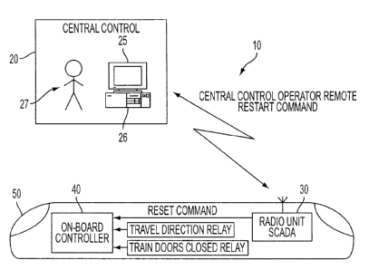
[13] FIG. 1 is an illustration of a train control system in accordance with
the present
invention.
DETAILED DESCRIPTION OF THE INVENTION
[14] As illustrated in FIG. 1, a train control system 10 in accordance with
the present
invention includes a central controller 20 including a computer 25 with a
processor 26, an
on-board radio unit 30, for example used in SCADA, and an on-board controller
40. The
term "on-board" refers to that equipment which is physically located on a
guideway vehicle
50, such as a train.
[15] During normal operation of the train control system in accordance with
the present
invention, the on-board controller 40 communicates with the central controller
20, for
example, over a wireless communication link. The communication between the on-
board
controller 40 and the central controller 20 enables controller 20 to perform
ATP and ATO
functions, as discussed above, as well as Automatic Train Supervision (ATS)
functions.
[16] ATS functions include monitoring and displaying the location of various
trains and
the health status of all ATC components; regulating the operation of the
irains within the -
system; establishing a man-machine interface; routing trains based on
destination/run and
schedule assignments; requesting switch moves and train reversals in
accordance with
destination/run assignments for various trains; modifying the system operating
parameters,
such as dwell times and maximum speeds in response to system delays andlor
commands
from a central operator; interfacing with communication subsystems and
displays;
collecting data for management reports; and interfacing with the station
platform
information displays and announcement systems.
4
CA 02461114 2004-03-15
[17] As long as everything is running smoothly, that is, there are no failures
in any of the
ATO, ATP or ATS functions, the trains within the system run virtually without
intervention
from the central control operator 27. However, once a problem arises in any of
these
functions, the on-board controller 40 of the effected train or trains is
disabled, thus
disabling the train, until the controller is reset.
[18] Specifically, according to one embodiment of the present invention, the
central
controller 20 systematically performs systems checks to verify proper
functioning of each
of the ATO, ATP and ATS systems with respect to various trains in the overall
ATC
system. If a failure in any of these functional systems is detected in any of
the trains, which
resulted in the automatic disabling of the respective on-board controller 40,
the central
controller 20, via the central control operator 27, issues a restart command
to the effected
train or trains. The restart command is transmitted from the remotely located
central
controller 20 to, for example, the radio unit 30, which can be part of a SCADA
system,
located onboard the particular train or trains 50 exhibiting the failure.
[19] After receiving the restart command from the central controller 20, the
SCADA 30
transmits a reset command to the failed on-board controller 40. After
receiving the reset
command from the SCADA 30, the on-board controller runs through its reset
procedure. In
particular, once the on-board controller 40 receives the reset command, it
determines
whether the travel direction of the train 50 changed during the time of th6
failure, i.e.,
during the time the controller 40, and hence the train 50, was disabled. This
check is
performed to ensure that the train was not driven manually during the time of
failure in the
opposite direction to that which it was originally traveling prior to the
failure. For example,
whether or not the train has moved in the opposite direction during the time
of failure is
determined by the travel direction relay which is also used to command
movement of the
train after the reset.
CA 02461114 2004-03-15
[20] In addition to checking the direction of movement of the train,
controller 40 also
checks the door closure status via the train door relay to determine if any of
the train doors
were opened during the time of the controller failure. This information
assists in
determining whether passengers have attempted to leave or have left the train
during the
failure. If passengers have exited the train, they might be on the guideway
and caution
should be used before the train is once again set in motion.
[21] If the direction of travel was not changed and the train doors were not
opened during
the time the controller 40 was disabled, the on-board controller 40 will then
command the
train to travel at a slow speed, e.g., approximately 5km/h, in order to
establish position.
Establishing position requires the controller 40 to detect two positioning
markers that are
disposed approximately 50 meters apart on the trackside.
[22] Specifically, relative train position determination can be accomplished
using a
combination of wayside and on-board devices. These devices include
transponders, a
Transponder Interrogator (TI) unit and two independent tachometers.
[23] Passive transponder tags are mounted on the guideway at locations
corresponding to
codes in the ATP database. Each time the train passes a guideway transponder,
the TI unit
receives the transponder's uniquely coded ID. At this time, the TI unit
serially passes the
...
transponder ID to the ATP Unit for processing. The ATP Unit verifies that the
transponder
ID received is valid using the following criteria: the transponder ID exists
in the ATP
database; the transponder ID received was expected based on the previous
transponder IDs
received; and the transponder was received within the appropriate distance
after the
previous transponder. The guideway position associated with the verified
unique
transponder ID is then retrieved from a stored table. This position is used
for the absolute
position of the train.
6
CA 02461114 2004-03-15
[24] Fine positioning between transponders is determined from the input of the
two
independent tachometers. The distance input from the two tachometers is
compared to
ensure that no large discrepancy exists between them. If a significant
discrepancy is
detected, the train is "emergency-braked" and the position of the train is set
to
"undetermined."
[25] To further verify the tachometer distance inputs, the tachometer velocity
inputs are
integrated to determine the distance traveled by the train. If a discrepancy
exists between
the registered tachometer distance inputs and the integrated tachometer
velocity inputs, the
train is again "emergency-braked" and the position of the train is set to
"undetermined."
[26] The direction of movement can be established from the information stored
in the ATP
database and a sequence of the transponder IDs. Also, the information provided
by the
tachometers on the train includes direction information. Once the position of
the train is
established, the controller may resume automatic operation.
[27] If, however, it is determined that during the time of the controller
failure the original
travel direction was changed or the train doors have been opened, or if the
train travels after
being reset for a predetermined distance without its position being
established, the
automatic restart is abandoned and a manual restart is required.
[28] The above description of the preferred embodiment has been given by way
of
example. From the disclosure given, those skilled in the art will not only
understand the
present invention and its attendant advantages, but will also find apparent
various changes
and modifications to the structures and methods disclosed. It is sought,
therefore, to cover
all such changes and modifications as fall within the spirit and scope of the
invention, as
defined by the appended claims, and equivalents thereof.
7