Note: Descriptions are shown in the official language in which they were submitted.
CA 02461161 2004-03-23
WO 03/026902 PCT/USO1/31405
EASILY ASSEMBLED GRIP ELEMENT
FIELD OF THE INVENTION
The present invention relates to a grip element for a hand-held andlor finger-
manipulated article. More particularly, the present invention relates to a
grip element which
is easily assembled onto an article, such as a hand-held or finger-manipulated
article.
BACKGROUND OF THE INVENTION
With the increasing attention to ergonomic designs, handle portions of hand-
held or finger-manipulated articles are increasingly designed to enhance
gripping thereof.
For instance, handles are often contoured and/or textured to facilitate
grasping. Such
formation of handles has been known for many years. It has become increasingly
desirable
to enhance gripping even further by providing a grip element formed from a
material
different from the material of the handle portion. The different material may
provide unique
1 S characteristics not achievable by the material from which the main body of
the handle must
be formed. For instance, hand-held and finger-manipulated articles may be
formed from
such materials as plastics or metals or woods which are hard andlor slippery.
The provision
of a grip element formed from a material different from that of the underlying
article, such
as rubber or foam, has become increasingly popular. Such grip elements may
provide such
benefits as reduced slippage (increased friction), an insulative effect (i.e.,
an element that is
not cold to the touch), and/or cushioning.
Various grip elements formed from a material different from the material of
the underlying article are known in the art. For instance, foam and rubber
grip elements
have been sold for many years for selective assembly onto a hand-held or
finger-
manipulated article to facilitate or to enhance grasping thereof. In addition,
hand-held and
finger-manipulated articles have also been sold with grip elements of
materials different
from the underlying material of the article already provided thereon. Such
grip elements
may be formed on the article by molding the material of the grip element onto
the different
underlying material of the article on Which the grip element is to be
provided.
Alternatively, such grip elements may be formed separately from the article
and then
assembled onto the article. The latter manner of formation of a grip element
generally tends
to be less expensive and more amenable to mass production, and thus is more
desirable.
However, although the actual formation of a separately formed grip element
may be simpler than formation of the grip element as an integral element of
the article,
assembly of the grip element onto the article may be difficult. Because the
grip element
may increase friction or may be formed from an elastomeric element {for
resiliency and
CA 02461161 2004-03-23
WO 03/026902 PCT/USO1/31405
cushioning effect), the grip element may not slide easily over the article.
Thus, various
techniques have been used to facilitate assembly of such grips onto an
article. For instance,
air may be blasted into the interior of a tubular elastomeric grip element to
cause the grip
element to expand. The grip element thus may readily be inserted over the grip
section of
an article. Once the air blast is discontinued, the grip element resumes its
natural
configuration, which typically has an inner diameter smaller than the outer
diameter of the
article, so that the grip element is secured onto the article. Similarly,
equipment for
mechanically stretching a grip element has been used. Alternatively, a
lubricant, such as
mineral spirits or isopropyl alcohol, may be used to reduce friction between
the grip element
and the article.
However, the above-mentioned manners of mounting a grip element all have
significant drawbacks. Using a blast of air is costly and generally is not
desirable. As may
be readily appreciated, machinery which mechanically stretches the grip
element is not only
costly, but also requires precision both in manipulating the grip element as
well as in
mounting the expanded grip element on the article. Finally, use of alcohol or
other types of
lubricants which are potentially flammable near assembly equipment has clear
inherent
risks.
Accordingly, it would be desirable to improve the manner in which a grip
element is mounted onto an article such that costs axe reduced, and speed and
efficiency in
assembly are increased.
SUMMARY OF THE INVENTION
The present invention is directed to a grip element for assembly onto a free
end of a hand-held, finger-held, or forger-manipulated article. One
application of the grip
element is to provide a comfortable grip for finger-manipulated articles, such
as writing
instruments, razors, toothbrushes, utensils, and tools. The grip element can
also be used
with larger articles that may be held in the palm of the user's hand, such as
impact tools
(e.g:, hammers), various sports equipments (e.g., rackets, bats, golf clubs),
and motor-driven
devices (e.g., power drills or motorcycles). The variety of articles on which
the grip
element of the present invention may be mounted are referenced herein as
"gripped articles"
for the sake of convenience only, and not with any intended limitation.
The grip element referenced herein includes a gripping surface and an
engagement surface extending from the gripping surface. The engagement surface
is
configured and dimensioned for engagement by a pushing device such that the
pushing
device may move the grip element substantially completely onto the gripped
article without
CA 02461161 2004-03-23
WO 03/026902 PCT/USO1/31405
requiring lubrication or separate expansion of the grip element. For example,
the
engagement surface may be a substantially planar surface that is angled, or
perpendicular to,
the gripping surface. The engagement surface is preferably provided at a
distal end of the
grip element, which is located furthest away from the proximal, free end of
the article.
Thus, the pushing device pushes the engagement surface onto the gripped
article, effectively
pulling the rest of the grip element.
To ease assembly of the grip element onto the gripped article, the inner
diameter of the grip element may increase, or taper outwardly, in a direction
from a
proximal end of the grip element (closest to the pushing device), toward a
distal end of the
grip element (furthest from the pushing device). In addition, the inner
diameter ofthe grip
element at the grip element distal end may be larger than the outer diameter
of the grip
section at the grip section proximal end, thus allowing the distal end of the
grip element to
slide readily over at least a portion of the grip section. Further, the inner
diameter of the
grip element at the grip element proximal end may be smaller than the outer
diameter of the
1 S grip section at the grip section proximal end to assist in retaining the
grip element on the
gripped article.
The present invention is also directed to a gripped article incorporating the
grip element. The article includes a grip section for receiving the above-
described grip
element.
The present invention is also directed to a method of assembling a grip
element onto a gripped article. The method includes the steps of contacting an
engagement
surface of the grip element, and pushing the engagement surface to move the
grip element
onto the article. The engagement surface may be positioned at a distal end of
the grip
element so that pushing on the engagement surface pulls a gripping portion of
the grip
element substantially completely onto the grip section of the article. A
tubular member,
such as a cap (in the case that the grip element is used for a writing
instrument), may be slid
over the grip element to contact the engagement surface. The method may
further include
contacting and pushing the end of the grip closest to the free end completely
onto the article.
These and other features and advantages of the present invention will be
readily apparent from the following detailed description of the invention, the
scope of the
invention being set out in the appended claims.
CA 02461161 2004-03-23
WO 03/026902 PCT/USO1/31405
BRIEF DESCRIPTION OF THE DRAWINGS
The detailed description will be better understood in conjunction with the
accompanying drawings, wherein like reference characters represent like
elements, as
follows:
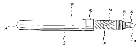
FIG. 1 is a perspective view of an illustrative embodiment of a gripped
article according to the present invention, shown as a writing instrument;
FIG. 2 is a side elevational view of the gripped article of FIG.1;
FIG. 3 is a side elevational view of the gripped article of FIG.1, with a cap
covering a free end of the gripped article;
FIG. 4 is a side elevational view of a grip element of the gripped article of
FIG.1;
FIG. 5 is a cross-sectional view of the grip element of FIG. 4;
FIG. 6 is a side elevational view of a body of the gripped article of FIG. 1;
FIG. 7 is a side elevational view of the cap of FIG. 3;
FIG. 8 is a cross-sectional view of the cap of FIG. 7; and
FIG. 9 is schematic representation of a method of assembling a grip element
onto a gripped article.
DETAILED DESCRIPTION OF THE INVENTION
The present invention is directed to a grip element, which may be applied to
any type of gripped article, such as writing instruments, razors,
toothbrushes, utensils, and
tools. The grip element can also provide grip or shock absorption for articles
which
transmit impact to the user, such as impact tools (e.g., hammers), various
sports equipments
(e.g., golf clubs and rackets), and motor-driven devices (e.g., power drills
or motorcycles).
For each application, the grip element is constructed accordingly to fit onto
a given article.
For illustrative purposes only, the present invention is shown and described
herein as a grip
element for a writing instrument.
Referring to FIG.1, an illustrative embodiment of a gripped article including
a grip element according to the present invention is shown as article 20.
Gripped article 20
generally includes an elongated body 30 having a grip element 50 disposed
thereon. While
body 30 is shown as having a generally circular cross-sectional geometry,
other geometries
are within the scope of the present invention, including rectangular, square,
triangular, oval,
and free-form.
Referring to FIGS. 2 and 6, body 30 is a generally elongated member having
a first free end 32, a second end 34, and a grip section 36 over which grip
element 50 is
CA 02461161 2004-03-23
JUL'08 2003 15:34 FR [,~
37~B~i9~8.h ,1, a.~. ~ .rTS
~ J U ~ 2003
provided. Typically, body 30 is formed of a relatively rigid material, such as
polypropylene.
As shown, grip section 36 is located betweEn first free end 32 and second end
34, and is
preferably located closer to first free end 3Z. Second end 34 may or may not
be a free end,
depending on the application of the grip element 50. Grip element 50 may be
positioned
substantially adjacent first free end 3~ to provide a gripping surface for a
user during use of
article 2Q . As shown in 1~1(x. 3~, a cap 90 may be placed over first free end
3~ (hidden in
fT~-. 3).
Referring to )frGS. 4 and 5, an illustrative embodime t of grip element 50 is
shown. Grip element 50 may be formed from an elastorneric material such as
rubber or foam,
but other materials known by one of ordinary skill in the art to be suitable
for gripping are
also within the scope of the present invention, For example, grip element 50
may be formed
from a polypropylene based thcrxnoplastic elastomer such as X60 sold by Teknor
Apex of
Pawtucket, Izhode Island, having a Shore A durometer of 60, Grip element 50 is
preferably
tubular in shape and defines a longitudxx~al axis 52 between a proximal end 54
and a distal
1 S end 56 which are longittadinally spaced from one another. .Distal end 56
is Longitudinally
spaced from first free end 32, As used herein, and as shown in the figures,
proximal
generally refers to a position adjacent the location from which grip element
50 is provided far
assembly (adjacent a pushing device), and distal generally refers to a
position. spaced
therefrom, away from the location from which grip element 50 is assembled over
body 30
(and away from the pushing device).
As shown in F',ICxS. 4 arid 5, grip element 50 includes a gripping surface 58
for
grippitng by a user. The gripping surface 58 defin.ts the longitudinal axis of
the grip element
S0. Gripping surface 58 may optionally be providEd with texture (e.g,, a
raised or recessed
pattern or an otherwise non-smooth surface) to provide enhar~cod grip and
comfort to a user
of gripped article 20. Grip element 50 also includes an engagement surface 70,
which is
canfigured far engagement with arl assembly tool such that the assembly tool
cans assemble,
or mono, grip element 50 onto body 30. The engagement surface 70 is located
substantially
adjacent the distal end 56. More particularly, engagement surface 70 is
disposed at an angle
with respect to gripping surface 58 and has an outer diameter 71 (shown in
FIB. 4) ~t is
su~ciently larger than outer diameter 6$ of gripping surface 58 (shown in FIG.
4) to permit
secure cugageznent by the assembly tool against engagement surface 70.
Preferably,
_5_
t
Received from < > at ll~Q3 3:3;33 PM (Eastern Dayight Time
CA 02461161 2004-03-23
JUL ~8 2~~3 15: 35 FR T,Q.~,17~37463958 P . 1
.- - j
'~ ~ ~ ~t ~~ ~ 2003
engagement surface 70 includes a substantially planar portion that is oriented
substantially
perpendicular or transverse to gripping surface SS. An assembly tool may thus
be placed in
contact with engagement surface 70, and moved with respect to body 30 to push
grip element
50 onto body 30. Preferably, the engagement of the assembly tool ox pushing
device against
e>lgagcment surface 70 is sufficient enough that additional assembly tools or
pushing devices
are z~ot necessary far completely assembling grip element 50onto body 30,
i.e., assistance of
additional assembly tools or pushing devices is not
-5A-
Ny'2: 14b!631.1
Received from < ? ~ Tl~(03 3:43:33 PM ~Eastem ~ayight Time
CA 02461161 2004-03-23
JUL 08 2003 15:35 FR T 17037463958 P.17
J l
q~,~~~'I. d ',
..
- ~, l.,. ~ ~'
necessary and the pushixlg device can push grip element 50 independently.
W'1len grip
element 50 is oriented such that engagement surface 70 slides onto body 30
before gripping
surface 58 (e.g., when engagement surface 70 is located at a distal end of
grip element 50),
only engagement surface 70 is pushed onto body 30, and gripping surface S8 is
effectively
pulled onto body 30. Because most of grip element 50 is thus pulled onto body
30, and not
pushed, deformation of grip element 50, such as bunching or collapsing, is
substantially
avoided.
A band 60, shown in FIG. 4, may optionally be provided on grip element 50
adjacent engagement surface 70. In the case band GO is provided, it
prefez'ably extends
distally from engagement surface 70 in a direction substantially along the
longitudinal axis.
Band 60 preferably has an outer diameter 66 (shown in FIG. 4) that is
substantially equal to
engagement surface outer diameter 71. As shown in FIG. 5, grip element SO has
an overall
length 6Z between the grip element proximal and distal ends and band 60 has a
band length
64 that may be less than about half of overall length 62 between the grip
element proximal
and distal ends. Preferably, band length 64 is about 20°l0 of overall
length bZ.
Gripping surface 58 and band 60 m.ay be integrally formed, or alternatively
formed as two separate parts and joined together, such as by bonding, welding,
or any other
suitable technique. Tn the case that gripping surface 58 and band 60 are
formed as two
separate parts and jained togtther, different materials may be used for caclx
portion to provide
desired properties to each of the respective parts, such as hardness, color,
ere,
Referring to FIG. 6, grip section 36 is shown. Grip section 3~ includes a
proximal cxtd 3$ and a distal end 40. Proximal end 38 is located proximate the
first free end
32 and distal end 40 is longitudinally spaced from proximal end 38 toward a
second free end
3d of body 30. Grip element 50 may be dirttensioned wittx respect to grip
section 36 to
provide, among other benefits, increased ease of assembly of grip element SO
onto grip
sectiozt 36, as will be descxl'bed in detail below. More specifically, and
with reference to
FIGS. 5 and 6, grip element inner diameter f8 rnay be dimensioned with respect
to grip
section outer diameter 42 such that grip element 50 slides at least partially
onto grip scctiorr
36 with substantially no interference between the two parts. 'The grip section
outer diameter
42 at the grip section proximal end 38 is larger than the grip element inner
diameter 78 at the
_6_
.et
flY2-141363!.!
J 5 l a J c
Received from < > at !(8t43 3:43:33 PM ~Easiem Day~ght Timed " ' . . - ~ ~ ~ ~
?, v , ~ . :e
CA 02461161 2004-03-23
JUL' 08 2003 15:35 FR TO 17037463958 P.18
'~ w.'r ~ ; : rr. , . ,
4 . , r ~ ~ ..~ w w~, '
~~p ~ J U L 2003
grip element proximal end S4. Thus, grip element 50 need not be treated or
fiurther
manipulated as in the prior art. preferably, these two diameters T8, 42 are
dimensioned such
that grip element SO may slide at least half way onto grip section 36 with
little or no
interference. This may be accomplished by providing grip element 50 with a:e
inner diameter
78 at grip element distal end 56 that is larger than the outer diameter 42 of
grip section 36 at
grip section proximal end 38. For e~cample, grip element izmer diameter T8 may
gradually
increase, or taper outward, from grip elennent pro~eimal end 54 to grip
element distal and 56,
Similarly, grip section outer diameter 42 may gradually increase, ox taper
Qutward, from grip
section proximal end 38 to grip sectioxl distal emd 44.
eet
- 6A -
rrYx: naam.i
Received from < > at 718103 3:43:33 Phl (Eastern Dayight Timed ~;-. ~,. :., '
, . ., ,
CA 02461161 2004-03-23
JUL ~8 2~~3 15:35 FR T~.17037463958 P.19
~ 1 / ~: -''.. ~ Li
In addition, grip section outer diameter 42 may, at at least a relatively
short
extent of grip section 36 proximal to grip section distal end 40, be smaller
than grip element
inner diameter 78 at grip elennent distal end 56, Grip section outer diameter
42 at distal end
40, however, preferably is larger than grip element inner diameter 78 at grip
element distal
end 56. Thus, grip element 50 may be positioned orz grip section 36 with
little or no
interference until grip element distal end 56 approaches grip section distal
end 40. An
assembly tool may then be used to engage and to push engage~nsnt surface 70
until grip
element distal end 5G is moved completely aver grip section distal end 40.
Contact at or near
grip element distal end 56 and grip section distal end 40 may thus primarily
secure grip
element 50 on grip section 36 by virtue of the differences in the respective
outer and inner
diameters, This configuration of grip element 50 and grip section 3C allows
grip elemexit 50
to be assembled onto grip section 36 without requiring lubrication or
expansion of grip
element 50 by compressed air or other mechanical assistance. Alternatively or
additionally,
grip element inner diameter 7S may, at a relatively shozt extent of grip
element proximal end
54, be smaller than grip section outer diameter 42 at grip section pro~.imal
end 38. Thus, grip
element 50 may additionally or alternatively be secured to grip section 36 by
contact with
grip section 36 at or near grip element proximal end 54 anal grip section
proximal end 38.
As fiuther shown in FrGS. 5 and 6, a. recess 74 may be formed in grip element
50 and define a recess inner diameter 76 that is larger than gripping surface
inner diameter
2U '1S. Recess 74 may be provided proximate grip element distal end 56 and
further ease
assembly of grip element 50 onto grip section 36. Additionally or
alternatively, a seat 44
may be provided adjacent grip section distal end 40, and have a seat outer
diameter 46 that is
~eatex titan grip section outer diameter 42. Seat outer diameter 46 may be
substantially
equal to, or slightly larger than, recess inner diameter 7t to further secure
grip element 50 on
~5 grip section 36. Seat 44 has a seat length 48 that is preferably
substantially equal to a recess
length 75 of recess 74 (shown in ~'IG. 5).
Grip element 50 may be configured such that it does not collapse upon itself
during assembly onto body 30. Additionally or alternatively, grip element SO
may be
configured to substantially resist deformation as it is assembled onto body
30. This may be
30 accornplishcd by forming grip element SO from a material having a
sufficient hardness ox
reduced flexibility, and/or by configuring grip element 50 to have a
sufficient wall thickness
g0 (shoran in F'rG. 5), Materials having a dummeter of between about 50 and 70
Shore A
deceived from < ~ at 118103 3:43;33 PM ~Eastem Dayight Timed AME~~ L~ E~ ~ f
~.~T
CA 02461161 2004-03-23
JUL ~8 20~3 15:36 FR
74~~5~ ~ ~ ~P~~
p 8 .sue 203
hardness have been found suitable to prevent deformation. Ixa addition, the
thiclozess of
band 60 preferably is selected such that band 60 does not collapse or
otherwise deform as it
is
et
_7A_
..,-.- rtra: tat3at.i
Received from < a at 1103 3:43:33 PM (Eastern Dayight Time,
CA 02461161 2004-03-23
JUL ~8 2~~3 15:36 FR
~~8~' ~ .1. ~ ~
p, ~ J U L X003
pushed over grip section 3~ to mount grip element 50 onto grip section 36. For
instance,
the thickness 61 of band fi0 (shown in FIG. 5) preferably is approximately I
nlln for a grip
made of a thermoplastic elastorner with an approximately 60 Shore A hardness,
Typically,
a 10. l ratio between the effective length of band 60 along thickness 61 is
desirable to
prevent deformation of band 60 during assembly.
ltefereing to FIGS. 7 and 8, an illustrative embodiment of a cap 90, which
may be positioned over the first free end 32 of body 30, when f~rmed as a
writing
instrument, is shown. Gap 90 preferably has an inner diameter 94 {shown in
pTG. 8) that is
slightly larger than outer diameter 68 of gripping surface S8 (shown in FIG. 4
), thus
allowYng cap 90 to slide freely over first free end 32 of body 30, for example
to conceal
writing element 100. 'When cap 90 is completely seated on body 30, at least a
portion of
grip element SO ntay extend outside cap 90, For example, as shown in FIG. 2,
at least a
portion of band 60, if provided, may extend outside cap 90 and be visible and
touchable by
a user of gripped article 20.
Gap 90 may be retained on body 30 solely by engagement with Flrst free end
32 of body 30, without engaging grip element 50. For example, as shown in
p'IGS. 6-8, a
resilient member 97 (shown for illustrative purposes only as a resilient ring)
may be
associated with cap 90 and configured and dimensioned to snap onto a cap
receiving section
98 formed on $rst free end 32. According to this configuration, inner diameter
94 of cog 90
(shown in ~'IG. 8) may be larger than outer diameter 68 of gripping surfac~ 58
(shown in
FrG. 4), thus preventing any wear or abrasion on gxip element SO when cap 90
is removed
and replaced on body 30. One of ordinary skill in the art will lmow and
appreciate that this
feature of the present invention is not limited to the rtsilxent membex 97 and
cap receiving
section 9$, and that other configurations nttay be utilized to hold cap 90 on
first &ee end 32.
Still referring to FIGS, 6-S, a vapor seat 96 , shown in p'IG. 8, may
optionally be provided on cap 90 to seal first free end 32 of gripped article
Z0. This may be
required when rnrriting element X00 includes a volatile marking medium. In the
instance
where vapor seal 96 is provided, resilitnt member 97 may be disposed oat vapor
seal 96,
such that vapor seal 96 engages cap receiving section 9$ and retains cap 90 on
body 30.
One of ordinary shill in the art will ftttther know and appreciate that vapor
seal 96 and
resilient x~aembcr 97 may be provided independently of one another (e.g.,
resilient member
_g_
Nva: ~s~m.i
Receired from < > at 118103 3:43;33 PM ~Eastem Dayight Timed AM~~ p ED a ~ ~
~'T
w
CA 02461161 2004-03-23
JIJL: 08 2003 15: 36 FR TO.~,~~I~~7~6395~ - P. ~'T~-,.
~ J ~ L~~0~3
97 may be providcd directly on cap 90, or vapor seal 96 may be providcd on cap
90 spite
cap 90 being retained on body 30 by attachment to somc point other than first
free end 32).
The inner and/or outer diameters of body 30, ~'ip element 50, band 6~ (if
provided), and cap 90 may optionally be dimensioned relative to one other to
provide a
-~.4-
NYz: ,uxai.,
Received from < > at 1(8103 3:43:33 FM ~Eastem Dayight Time]
CA 02461161 2004-03-23
JUL ~8 20~3 15 : 3~ FR ~~46~~8
IP~4lt~ ~ ~ J U L 2003
relatively smooth tapered outer surface of gripped article 20 , For example,
the o tar
diameter 92 of cap 90 may be substantially equal to the outer diameter 66 of
band 60 where
the two parts abut, providing a smooth transition between cap 90 and band 60 .
In addition,
body 30 may have a body outer diameter 49 at secozid end 34 that is
dimensioned such that
cap 90 may be snugly slid thereover and secured thereon for storage. Because
band 60 has
a larger diameter than tht proximal portion of body 30 (including grip section
36), and cap
90 rn~ust fit over such proximal portion as well as over distal second end 34,
the diameter 66
of bawd 60 is larger than the diameter of distal second a»d 34 as well as of
grip section 36.
Accordingly, body 30 may have a body transition outer diameter 49, shown in
FIG. 3, in
ardor to provide a smooth transition between first free end 32 of body 30 and
band 60 fox
an overall streamlined appearance when cap 90 is covering vu~riting element
100,
Furthermore, body trausitian outer diameter 49 may gradually decrease in a
direction from
band 60 to second end 34, such as by tapering toward second end 34.
l~efet'ring to FIG. 9, a method of asscntbling a grip element 50 onto a grip
I S section 36 of a gripped article is shown, To facilitate assembly of
gripped article 20, grip
element SO may be mounted at least partially onto grip section 36 and seated
thereon in
proper alignment with grip section 36 without much effort, thus providing a
"lead." This
may be accomplished, for example, by aligning grip element 50 over first free
end 3~ and
dropping it thereon sash that the grip clement 50 is substantially stabilized
an the article 20
prior to contacting the engagement surface %0 and moving the cngagcmtnt
surface 70 onto
the article 20. Grip elelntnt 50 preferably freely slides at least about half
way onto grip
section 36 (as a result of the relative dimensions of grip element 50 and grip
s~tion 36)
without requiring any moving force applied to engagement surface 70 and with
substantially na ixlterfercnce bctwe~n the grip element 50 and the grip
section 36, thus
providing a long "lead" For assembly at high speeds. This long "lead" is
especially desirable
for high speed assembly so tlxe pats fit together and are seated in proper
alignment before
any force is applied to the grip clement 50 to seat grip element 50
completely. The gap
element inner diameter 78 is larger than the grip section outer diameter 42
along at least
about half of the grip element length 62 such that the grip element 50 may be
freely dropped
over the grip section 36. Next, an assembly tool may contact and push
engagement surface
f0 to more engagement surface 70 along grip section 36. As a result, gripping
surface 58 is
pulled onto grip section 36. The assembly tool may include a tubular portion
that is
_g_
r .. ,_" -: ., _ . .~~ ~ NY2.:114763L1
Received from c > at 1f~(03 3:43;33 PM (Eastenl Day~ght Timed
CA 02461161 2004-03-23
JUL 08 2003 1 S : 37 FR 1'~,~~~',o;~J ~46~9"~8l l
~~;~ x ~ ~' J ~ L '2'1'003 '
received over gripping surface 58 and contacts azad pushes against cngageznent
surface 70 to
push grip element 50 onto grip sectiox! 36. In the case where the outer
diamctar 42 at the
proximal end 3g of grip section 36, closest to first free end 32, is larger
than the inner
diameter 7$ at proximal exld 54 of grip element SO (described above in
refercnee to FAG. C),
it may be preferable to contact and to push proximal end S4 of grip element 50
onto grip
section 36, to Fully seat grip element 50 on body 30.
According to an alternative embodiment, cap 90 may be uscd to assemble
grip element SO onto grip section 36, For example, cap 90 may have a wall
thickness
and/or
_9A_
rm~: ~a.m.~
Received from < > at x18143 3:43:~3 PM ~Eastem Dayight Timed
CA 02461161 2004-03-23
WO 03/026902 PCT/USO1/31405
inner diameter 94 that is dimensioned to make sufficient contact with
engagement surface
70 to push grip element 50 onto grip section 36. Thus, after grip element 50
is at least
partially mounted onto grip section 36, as discussed above, cap 90 may be
placed at least
partially over grip element 50 and placed in contact with engagement surface
70. Cap 90
may then be moved further to push grip element 50 completely onto grip section
36. Tf cap
90 is provided with a vapor seal 96, as shown in FIGS. 7 and 8, the vapor seal
96 may be
dimensioned and configured to engage proximal end S4 of grip element 50 and
fully seat
grip element 50 onto body 30. By using cap 90 as the assembly tool, the
efficiency of
assembling gripped article 20 is increased by installing grip element 50 and
cap 90 onto
body 30 in a single operation.
Although the above method~is illustrated and discussed in reference to
components of a writing instrument, this is for illustrative purposes only,
and the present
inventive method is in no way to be limited to any of the above-described
structures. Thus,
a grip element may be formed and assembled in accordance with the principles
of the
present invention for assembly over any gripped article.
Furthermore, while the foregoing description and drawings represent the
preferred embodiments of the present invention, it will be understood that
various additions,
modifications and substitutions may be made therein without departing from the
spirit and
scope of the present invention as defined in the accompanying claims. In
particular, it will
be clear to those skilled in the axt that the present invention may be
embodied in other
specific forms, structures, arrangements; proportions, and with other
elements, materials,
and components, without departing from the spirit or essential characteristics
thereof. One
skilled in the art will appreciate that the invention may be used with many
modifications of
structure, arrangement, proportions, materials, and components and otherwise,
used in the
practice of the invention, which are particularly adapted to specific
environments and
operative requirements without departing from the principles of the present
invention. The
presently disclosed embodiments are therefore to be considered in all respects
as illustrative
and not restrictive, the scope of the invention being indicated by the
appended claims, and
not limited to the foregoing description.
to