Note: Descriptions are shown in the official language in which they were submitted.
CA 02461217 2004-03-22
WO 03/026719 PCT/IL02/00791
CRYOPLASTY APPARATUS AND METHOD
FIELD AND BACKGROUND OF THE INVENTION
The present invention relates to apparatus, systems, and methods
utilizing cryogenic cooling in an angioplasty balloon catheter for treatment
of
arterial stenosis and prevention of restenosis. More particularly, the present
invention relates to an angioplasty balloon catheter utilizing expansion of
compressed gas to effect Joule-Thomson cooling of an angioplasty balloon, and
optionally further incorporating external temperature sensors utilizable to
identify a locus for treatment of arterial stenosis. The present invention
further
relates to angioplasty treatment systems incorporating such a catheter, and to
cryogenic angioplasty methods for treating arterial stenosis and discouraging
restenosis.
It is a well-known problem of angioplastic surgery that blood vessels
having been subjected to angioplastic treatment have a marked tendency to
. undergo restenosis. Blood vessels having displayed improved vascular flow as
result of an angioplasty intervention are often observed to suffer a
subsequent
re-narrowing of the vessel, again impeding vascular flow, in the weeks and
months following the angioplasty intervention. Such restenosis is currently
understood to be a reaction of vascular tissues to the angioplastic procedure,
or
to the ongoing endovascular insult.
Cooling of the site during or immediately following angioplasty has
been found to impede or prevent restenosis. A number of patents have been
issued relating to devices for cryogenic cooling of tissues during or after
angioplasty, and to angioplasty methods using cooling devices.
U.S. Patent 5,868,735 to Daniel M. Lafontaine, and U.S. Patent
6,290,686, also to Lafontaine, both refer to cryogenic cooling of an
angioplasty
apparatus, as does U.S. Patent Application 20020032438 by Lafontaine.
Lafontaine teaches a method whereby a balloon catheter is advanced to a
target site, the balloon is inflated, and coolant is delivered into the
inflated
CA 02461217 2004-03-22
WO 03/026719 PCT/IL02/00791
2
balloon to freeze a portion of a lesion adjacent to the balloon, to kill cells
within the lesion.
It is, however, a limitation of the above-mentioned Lafontaine patents
and patent application that the implementations described are limited to
S cryogenic cooling by evaporation of a liquid.
As is well known, evaporation from a liquid cools that liquid. If a
liquid, such as for example liquid nitrogen, is maintained under pressure to
prevent boiling, and then is passed into an area where it is free to expand,
released pressure allows boiling or rapid evaporation of the liquid, cooling
both
the liquid and the resultant gas.
Cooling by evaporation is described by Lafontaine as the method of
choice for cryogenic cooling of a cryoplasty balloon catheter to effect
cooling
of tissues at an angioplasty site. We note that although claim 13 of U.S.
Patent
6,290,686 op. cit. is couched in general terms, in that Lafontaine refers to
delivering coolant into the balloon and allowing the coolant to undergo a
phase
change within the balloon, the phase change actually described within
Lafontaine's disclosure is a phase change from liquid to gas, that is, cooling
by
evaporation.
U.S. Patent Application 20020010460, submitted by James Joye et. al.
similarly refers to a cryosurgery probe usable to perform angioplasty, which
probe enables cryogenic cooling of tissues at an angioplasty site. Joye refers
to
an apparatus in which a single balloon may function for both cryogenic cooling
and for dilation.
Joye's application similarly contemplates cooling by evaporation.
Throughout his disclosure, Joye presents and discusses cooling by evaporation
from supplied cooling liquids or liquid/gas mixtures such as carbon dioxide
(CO2), nitrous oxide (N20), liquid nitrogen (N2), a
fluorocarbon
such as AZ-SO.TM. (sold by Genetron of Morristown, N.J.), or the like.
Similar systems are presented U.S. Patent 6,355,029 to Joye et. al. and in
U.S.
Patent 5,971,979, also to Joye et. al.
CA 02461217 2004-03-22
WO 03/026719 PCT/IL02/00791
3
It is to be noted that in each of the above-mentioned documents Joye
refers in passing to the possibility of use of a Joule-Thomson orifice in the
delivery of a cryogenic cooling fluid into an angioplasty balloon, yet in each
of
the documents, all of the implementation details refer to delivery of a liquid
rather than a gas into a balloon or other volume to be cryogenically cooled.
In
this sense, the embodiments described in detail by Joye are similar to those
described by Lafontaine in the patents cited hereinabove, in that evaporation
of
a liquid, a phase transition from a liquid to a gaseous state, is the cooling
mechanism described. Thus, for example, Joye states in one context "the
cryogenic fluid will flow through the tube 22 as a liquid at an elevated
pressure
and (thus inhibiting flow restrictive film boiling) will expand across the
orifice
23 to a gaseous state at a lower pressure within the balloon." And similarly:
"The methods of the present invention may be performed with cryosurgical
catheters comprising a catheter body having a proximal end, a distal end, and
a
primary lumen therethrough. The primary lumen terminates in a
Joule-Thomson orifice at or near its distal end, and a balloon is disposed
over
the orifice on the catheter body to contain a cryogenic fluid delivered
through
the primary lumen. Suitable cryogenic fluids will be non-toxic and include
liquid nitrogen, liquid nitrous oxide, liquid carbon dioxide, and the like. By
delivering the cryogenic fluid through the catheter body, the balloon can be
expanded and cooled in order to effect treatments according to the present
invention."
Thus, it is to be noted that although Joye employs the term
"Joule-Thomson orifice", he uses it to describe a system wherein a pressurized
liquid passes into a region where it is enabled to evaporate, thereby to
effect
cooling. This is to be contrasted to the embodiments to be described
hereinbelow, wherein the cryogenic fluid delivered to an expandable balloon is
a pressurized gas, not a liquid nor a liquid/gas mixture, and wherein
expansion
of a pressurized gas, and not evaporation of a liquid, is the cooling
mechanism.
Although the two methods are similar in that both allow for expansion of a
CA 02461217 2004-03-22
WO 03/026719 PCT/IL02/00791
4
compressed fluid, they are also, in a sense, almost opposite, in that the
phase
change initiated by delivery of a pressurized liquid into the balloon volume
is a
phase change from liquid to gas, whereas in a true Joule-Thomson delivery
system a gas is allowed to expand, and by expansion to cool, and the result of
that cooling process may even be, in some cases, a phase transition in the
opposite direction, whereby the expanded gas is cooled to such an extent that
a
portion of the expanded gas actually condenses back into liquid phase.
Various other patents similarly refer to cooling by evaporation as a
method of cryogenic cooling of an angioplasty balloon catheter. U.S. Patent
Application 20020045892 by Hans W. Kramer is an additional example of a
system utilizing evaporation of a liquid such as perfluorocarbon to achieve
cryogenic cooling in a balloon catheter. U.S. Patent 5,147,355 to Peter
Friedman is yet another example of a system utilizing evaporation of a liquid
to
achieve cryogenic cooling.
Cooling by evaporation, however, presents a variety of disadvantages.
Cooling by evaporation is relatively slow when compared, for example,
to true Joule-Thomson cooling, that is, when cooling by evaporation is
compared to cooling by allowing rapid expansion of a compressed gas.
Further, evaporative cooling is not amenable to exact control of the
cooling process, because evaporation is not instantaneous. Introducing into an
angioplasty balloon a liquid which cools by evaporation inevitably introduces
an intrinsic lag in any possible control of the cooling process, because
halting
the supply of cooling fluid does not immediately halt cooling. Liquid
previously introduced into a balloon and not yet evaporated will continue to
cool even after supply of additional cooling liquid has been halted. In the
surgical context of angioplasty interventions, where treatment typically
necessitates blocking of arteries during a procedure, speed of operation and
fine
control of temperatures are of great importance.
Thus, there is a widely felt need for, and it would be highly
advantageous to have, an apparatus and method of cooling an angioplasty
CA 02461217 2004-03-22
WO 03/026719 PCT/IL02/00791
balloon which provide for rapid cooling and optional rapid heating of an
angioplasty balloon, and which enable accurate, rapid, and exact control of
temperatures within the angioplasty balloon and/or in the treated body
tissues.
Joye's discussion of uses of his invention, in the documents cited above,
5 points up several additional problematic aspects of cryogenic cooling by
evaporation. Joye describes the difficulty of achieving an optimal cooling
temperature at a target region, and further describes the difficulty of
achieving
an even cooling distribution throughout a target region.
With respect to maintenance of a desired temperature within the cooling
apparatus, Joye points out that it is in many cases desirable to invoke
apoptosis
and/or programmed cell death so as to inhibit hyperplasia and/or neoplasia of
a
blood vessel related to angioplasty, stenting, rotational or directional
artherectomy, or the like, and he further points out that in order to invole
apoptosis (rather than simply destroying tissues by radical deep freezing) it
will
often be desirable to provide more moderate cryogenic treatment temperatures
than those automatically provided by an uncontrolled evaporation process.
Joye does not, however, provide a method of achieving exact control of cooling
within the target regions. Indeed, he points out that cooling is generally
enhanced by minimizing pressure within the angioplasty balloon. This link,
between pressure of gas within an inflated balloon and the amount of cooling
of that balloon, is one of the disadvantages of using an evaporation process
to
achieve cryogenic cooling of an angioplasty balloon.
Thus, there is a widely recognized need for, and it would be highly
advantageous to have, an apparatus and method of cryogenic cooling in an
angioplasty balloon catheter which provides for exact control of temperature
within a balloon in a manner relatively independent of the dilation pressure
maintained in that balloon.
With respect to the well-known difficulty of achieving an even cooling
distribution throughout a target region, Joye discusses the fact that
evaporative
cooling tends to cool an apparatus unevenly, parts of the apparatus adjacent
to a
CA 02461217 2004-03-22
WO 03/026719 PCT/IL02/00791
6
lumen through which cooling fluid is supplied being significantly colder than
more distant parts of the apparatus. In an attempt to deal with the problem,
Joye proposes a method distribution of a cryogenic liquid from a supply lumen
into a cryogenic balloon, utilizing a diffuser that causes the cooling fluid
to be
distributed both radially and axially. The contemplated diffuser comprises a
tubular structure with radially oriented openings. Joye points out that as the
openings are radially oriented, the diffuser will direct the cooling fluid
roughly
perpendicularly toward the wall of the cryogenic balloon, thereby encouraging
even heat transfer between the cooling vapor and balloon wall. Joye teaches
that distribution of ports circumferentially and axially along the balloon
provides a substantially uniform cooling over a significant portion of (often
over the majority of) the surface of the balloon. A similar system is also
described by Joye in U.S. Patent 6,355,029. We note however that according
to Joye's own description, the desired uniformity is not expected to extend
over
the entire surface of the balloon, and in many cases will not extend even to
the
majority of the balloon surface.
Thus, there is a widely recognized need for, and it would be highly
advantageous to have, apparatus and method of cryogenic cooling of the
balloon of an angioplasty balloon catheter, which method and apparatus
provide for accurate control of temperature of the balloon during cooling, and
further provide a highly evenly distribution of cold throughout that balloon
catheter.
With respect to another aspect of cryogenic balloon angioplasty, U.S.
Patent Application 20020045894 by James Joye et. al. presents an additional
system for cryogenic cooling by evaporation, this system comprising a double
balloon catheter, a first balloon being inflated by a pressurized gas, and a
second balloon containing the first balloon, with a vacuum between the two.
In U.S. Patent Application 20020045894 Joye presents a safety interlock
system, whereby a rise in pressure in the outer balloon is interpreted to
signal a
leak in the inner balloon, and detection of such a rise in pressure causes his
CA 02461217 2004-03-22
WO 03/026719 PCT/IL02/00791
7
system to cut off supply of pressurized fluid to the inner balloon, thereby
avoiding an irruption of pressurized fluid into the tissues of a patient
undergoing a surgical intervention. We note, however, a disadvantage of the
described safety interlock system, in that it is designed to detect such a
leak
only after a significant rise in pressure has occurred within the outer
balloon.
Thus, there is a widely recognized need for, and it would be highly
advantageous to have, a system for detecting a leak in such a balloon
angioplasty system, which detection is highly sensitive to even very small
leaks
in an inner angioplasty balloon, thereby enabling to immediately cease supply
of input fluids, and to undertake other or additional corrective measures, as
soon as such a very small leak is detected, and without necessitating waiting
for
a leak large enough to significantly raise pressure in an outer balloon
volume.
Referring now to other aspects of prior art, it is noted that one of the
basic problems inherent in angioplasty and similar surgical interventions is
the
need to effect correct placement of an angioplasty balloon catheter prior to
performance of angioplasty. There is thus a widely recognized need for, and it
would be highly advantageous to have, apparatus and method enabling accurate
placement of an angioplasty balloon catheter based information garnered at a
potential intervention site, by an angioplasty balloon catheter, in real time.
SUMMARY OF THE INVENTION
According to one aspect of the present invention there is provided an
angioplasty balloon catheter useable to treat arterial stenosis, comprising a
gas
input lumen for supplying a pressurized gas, a first inflatable balloon
containing a first variable volume, and a Joule-Thomson orifice for passing
the
pressurized gas from the gas input lumen into the first variable volume so as
to
cool and inflate the first inflatable balloon.
According to further features in preferred embodiments of the invention
described below, the catheter further comprises a first gas exhaust lumen for
exhausting gas from the first variable volume of the first inflatable balloon.
CA 02461217 2004-03-22
WO 03/026719 PCT/IL02/00791
8
The catheter may comprise an exhaust control valve for controlling exit of
exhaust gasses from the first gas exhaust lumen, and the exhaust control valve
may be operable to regulate pressure within the first variable volume.
According to still further features in preferred embodiments of the
invention described below, the catheter further comprises a heat exchanging
configuration designed and constructed to facilitate transference of heat
energy
between the gas input lumen and the first gas exhaust lumen. The first gas
exhaust lumen may be positioned contiguous to at least a portion of the gas
input lumen, thereby constituting a heat exchanging configuration. The heat
exchanging configuration may comprise a section wherein the gas input lumen
is positioned within the first gas exhaust lumen and may have fins for
facilitating heat exchange. Alternatively, first gas exhaust lumen may be
positioned within the gas input lumen, and may have fins for facilitating heat
exchange. Alternatively, the heat exchanging configuration comprises a
section wherein the gas input lumen is spirally wrapped around the first gas
exhaust lumen. Alternatively, the heat exchanging configuration comprises a
section wherein the first gas exhaust lumen is spirally wrapped around the gas
input lumen. The heat exchanging configuration may comprise a secondary
Joule-Thomson orifice connected to a source of compressed gas.
According to further features in preferred embodiments of the invention
described below, the Joule-Thomson orifice is shaped and oriented so as to
induce in gasses passing therethrough into the first variable volume a motion
selected from a group consisting of circular motion, swirling motion, and
turbulent motion. The catheter may further comprising a plurality of
Joule-Thomson orifices, which may be shaped and oriented so as to induce in
gasses passing therethrough into the first variable volume a motion selected
from a group consisting of circular motion, swirling motion, and turbulent
motion.
According to further features in preferred embodiments of the invention
described below, the first variable volume of the first inflatable balloon
further
CA 02461217 2004-03-22
WO 03/026719 PCT/IL02/00791
9
comprises a flow control structure designed and constructed to influence
circulation of moving gasses within the first variable volume. Preferably, the
flow control structure comprises at least one of a group consisting of flow
directors for enhancing circular flow, multiple internal channels for
subdividing
flow, and spoilers for increasing turbulence.
According to further features in preferred embodiments of the invention
described below, the catheter further comprises a second inflatable balloon
hermetically containing the first inflatable balloon and defining a second
variable volume interior to the second inflatable balloon and exterior to the
first
inflatable balloon, and may comprise a heat-transmitting material contained
within the second volume, prefereably selected from a group consisting of a
liquid material and a gel material.
According to further features in preferred embodiments of the invention
described below, the catheter further comprises a second gas exhaust lumen for
exhausting gas from the second volume.
According to further features in preferred embodiments of the invention
described below, the catheter further comprises a guide-wire lumen enabling
passage of a guide wire through the catheter and an injection lumen suitable
for
injecting a contrast medium near a distal portion of the catheter.
According to further features in preferred embodiments of the invention
described below, the catheter further comprises a moveable thermal sensor
operable to report external temperatures at selected positions along a
selected
length of the catheter, thereby enabling the catheter to report a temperature
gradient along a selected segment of a body conduit when the catheter is
inserted into the body conduit and the moveable thermal sensor is moved along
the catheter. The moveable sensor may be a fiber optic element moveable
along the catheter and connectable to a thermographic camera external to the
catheter. Alternatively, the catheter further comprises a plurality of thermal
sensors operable to report external temperatures along a selected length of
the
catheter, thereby enabling the catheter to report a temperature gradient along
a
CA 02461217 2004-03-22
WO 03/026719 PCT/IL02/00791
selected segment of a body conduit when the catheter is inserted into the body
conduit. The thermal sensors are preferably selected from a group comprising
a thermocouple sensor, a thermographic camera sensor, and a fiber-optic
element connectable to a thermographic camera sensor external to the catheter.
5 According to further features in preferred embodiments of the invention
described below, the thermal sensors are spirally configured around and along
a
section of the catheter, and the catheter further includes a data
communication
element for communicating data generated by the thermal sensors to a data
receiver outside of the catheter. The data communication element may
10 comprise a wire or a wireless communicator.
According to further features in preferred embodiments of the invention
described below, at least one of the plurality of thermal sensors comprises a
hair-like fiber for enhancing transmission of heat between the at least one
sensor and a body tissue adjacent to the sensor.
According to further features in preferred embodiments of the invention
described below, the plurality of thermal sensors are distributed along an
expandable spiral sensing loop having a distal end anchored to a distal
portion
of the catheter, the sensing loop being spirally wound around a section of
shaft
of the catheter and being operable to expand away from the shaft, thereby
enhancing thermal communication between the sensors distributed along the
sensing loop and body tissues adjacent to the catheter.
The spiral sensing loop may be designed and constructed to expand
away from the shaft of the catheter when a proximal end of the sensing loop is
pushed toward the anchored distal end of the sensing loop, or be designed and
constructed to contract toward the shaft of the catheter when a proximal end
of
the sensing loop is pulled away from the anchored distal end of the sensing
loop.
According to yet another aspect of the present invention there is
provided a thermal sensing device designed and constructed to be spirally
wrapped around a catheter insertable into a body conduit, the thermal sensing
CA 02461217 2004-03-22
WO 03/026719 PCT/IL02/00791
11
device having a distal end designed and constructed to be anchored to a distal
portion of the catheter, the thermal sensing device comprising a plurality of
thermal sensors mounted on a spring-like spiral base operable to expand away
from the catheter, the expansion enhancing thermal contact between the
thermal sensors and tissue of the body conduit, thereby enabling the thermal
sensing device to report tissue temperatures along a selected length of the
body
conduit.
The thermal sensing device of may be designed and constructed to
expand away from the catheter when a proximal end of the sensing device is
pushed toward the anchored distal end of the sensing device, or designed and
constructed to contract towards the catheter when a proximal end of the
sensing
device is pulled away from the anchored distal end of the sensing device.
According to a further aspect of the present invention there is provided
a~: angioplasty balloon catheter comprising a moveable thermal sensor operable
to~'report external temperatures along a selected length of the catheter, and
thereby operable to report a temperature gradient along a selected segment of
a
body conduit when the catheter is inserted into the conduit and the sensor is
moved along the catheter. The moveable sensor may be a fiber optic element
moveable along the catheter and connectable to a thermographic camera
external to the catheter.
According to yet another aspect of the present invention there is
provided an angioplasty balloon catheter comprising a plurality of thermal
sensors operable to report external temperatures along a selected length of
the
catheter, the catheter being operable to report a temperature gradient along a
selected segment of a body conduit when the catheter is inserted into the body
conduit. The thermal sensors are preferably selected from a group comprising
a thermocouple sensor, a thermographic camera sensor, and a fiber-optic
element connectable to a thermographic camera sensor external to the catheter,
and may be arranged in a spiral configuration around and along a section of
the
catheter. The catheter may further include a data communication element for
CA 02461217 2004-03-22
WO 03/026719 PCT/IL02/00791
12
communicating data generated by the thermal sensors to a data receiver outside
of the catheter. The data communication element may comprise a wire or a
wireless communicator.
According to further features in the described preferred embodiments, at
least one of the plurality of thermal sensors comprises a hair-like fiber for
enhancing transmission of heat between the at least one sensor and a body
tissue adjacent to the sensor.
According to still further features in the described preferred
embodiments, the plurality of thermal sensors are distributed along an
expandable spiral sensing loop having a distal end anchored to a distal
portion
of the catheter, the sensing loop being spirally wound around a section of
shaft
of the catheter and being operable to expand away from the shaft, thereby
enhancing thermal communication between the sensors distributed along the
sensing loop and body tissues adjacent to the catheter.
The spiral sensing loop may be designed and constructed to expand
away from the shaft of the catheter when a proximal end of the sensing loop is
pushed toward the anchored distal end of the sensing loop. Alternatively, the
spiral sensing loop is designed and constructed to contract toward the shaft
of
the catheter when a proximal end of the sensing loop is pulled away from the
anchored distal end of the sensing loop.
According to yet another aspect of the present invention there is
provided a system for angioplastic treatment of arterial stenosis and for
reducing restenosis, comprising: an angioplasty balloon catheter useable to
treat arterial stenosis, having a gas input lumen for supplying a pressurized
gas,
a first inflatable balloon containing a first variable volume, and a
Joule-Thomson orifice for passing the pressurized gas from the gas input lumen
into the first variable volume of the first inflatable balloon so as to cool
and
inflate the first inflatable balloon; a supply of compressed cooling gas
operable
to supply cooling gas to the gas input lumen; and a cooling gas input valve
CA 02461217 2004-03-22
WO 03/026719 PCT/IL02/00791
13
controlling delivery of compressed cooling gas from the supply of compressed
cooling gas to the gas input lumen.
Preferably, the angioplasty balloon catheter further comprises a first gas
exhaust lumen for exhausting gas from the first variable volume of the first
inflatable balloon, a gas exhaust valve for controlling passage of gas out of
the
gas exhaust lumen, and a heat exchanging configuration designed and
constructed to facilitate transference of heat energy between the gas input
lumen and the first gas exhaust lumen.
Preferably, at least a portion of the first gas exhaust lumen is positioned
contiguous to at least a portion of the gas input lumen, thereby constituting
a
heat exchanging configuration. Alternatively, the heat exchanging
configuration comprises a section wherein the gas input lumen is positioned
within the first gas exhaust lumen, and the gas input lumen, positioned within
the first gas exhaust lumen, comprises fins for facilitating heat exchange.
Further alternatively, the heat exchanging configuration comprises a section
wherein the first gas exhaust lumen is positioned within the gas input lumen
and comprises fins for facilitating heat exchange. Further alternatively, the
heat exchanging configuration comprises a section wherein the gas input lumen
is spirally wrapped around the first gas exhaust lumen, or a section wherein
the
first gas exhaust lumen is spirally wrapped around the gas input lumen.
Further
alternatively, the heat exchanging configuration comprises a secondary
Joule-Thomson orifice connected to a source of compressed gas.
According to still further features in the described preferred
embodiments, the Joule-Thomson orifice is shaped and oriented so as to induce
in gasses passing therethrough into the first variable volume a motion
selected
from a group consisting of circular motion, swirling motion, and turbulent
motion.
According to still further features in the described preferred
embodiments, the first inflatable balloon further comprises a plurality of
Joule-Thomson orifices.
CA 02461217 2004-03-22
WO 03/026719 PCT/IL02/00791
14
According to still further features in the described preferred
embodiments, the first inflatable balloon further comprises a plurality of
Joule-Thomson orifices shaped and oriented so as to induce in gasses passing
therethrough into the first variable volume a motion selected from a group
consisting of circular motion, swirling motion, and turbulent motion.
According to still further features in the described preferred
embodiments, the first variable volume of the first inflatable balloon further
comprises a flow control structure designed and constructed to influence
circulation of moving gasses within the first variable volume.
According to still further features in the described preferred
embodiments, the flow control structure comprises at least one of a group
consisting of flow directors for enhancing circular flow, multiple internal
channels for subdividing flow, and spoilers for increasing turbulence.
According to still further features in the described preferred
embodiments, the catheter further comprises a second inflatable balloon
hermetically containing the first inflatable balloon and defining a second
variable volume interior to the second inflatable balloon and exterior to the
first
inflatable balloon.
According to still further features in the described preferred
embodiments, a heat-transmitting material is contained within the second
variable volume, the material selected from a group consisting of a liquid
material and a gel material.
According to still further features in the described preferred
embodiments, the angioplasty balloon catheter further comprises a guide-wire
lumen enabling passage of a guide wire through the catheter.
According to still further features in the described preferred
embodiments, the catheter comprises an injection lumen suitable for injecting
a
contrast medium near a distal portion of the catheter.
CA 02461217 2004-03-22
WO 03/026719 PCT/IL02/00791
This system preferably comprises a second gas exhaust lumen for
exhausting gas from the second internal volume, and a helium detector
operable to detect presence of helium in the second gas exhaust lumen.
According to still further features in the described preferred
5 embodiments, the system comprises a supply of compressed heating gas
operable to supply heating gas to the gas input lumen, and has a heating gas
input valve controlling delivery of compressed heating gas from the supply of
compressed heating gas to the gas input lumen.
According to still further features in the described preferred
10 embodiments, the system further comprises a supply of a gas mixture
comprising compressed cooling gas and compressed heating gas, and has a
mixed-gas input valve controlling delivery of mixed gas from the supply of a
gas mixture to the gas input lumen. Alternatively, the system has a
gas-proportion input valve controlling a ratio of cooling gas to heating gas
in
15 the supplied mixture of compressed cooling gas and compressed heating gas.
Preferably, the supply of a gas mixture comprising compressed cooling
gas and compressed heating gas is operable to supply a gas which produces no
significant thermal effect when passed from a region of high pressure to a
region of low pressure through a Joule-Thomson orifice. Preferably, the supply
of a gas mixture is operable in a first time to supply a gas which produces no
significant thermal effect when passed from a region of high pressure to a
region of low pressure through a Joule-Thomson orifice, and further operable
in a second time to supply a cooling gas.
According to still further features in the described preferred
embodiments, the system further comprises a vacuum pump for rapidly
withdrawing gas from the first variable volume of the first inflatable balloon
through the first gas exhaust lumen, and/or a vacuum pump for rapidly
withdrawing gas from the second internal volume through the second gas
exhaust lumen.
CA 02461217 2004-03-22
WO 03/026719 PCT/IL02/00791
16
According to still further features in the described preferred
embodiments, the system further comprises a control unit for controlling
functioning of the catheter, the control unit comprising a data collection
unit
for receiving data generated by at least one sensor positioned in or near a
distal
portion of the catheter, a processing unit for evaluating data received by the
data collection unit according to a stored algorithm, and a command module for
sending commands to at least one remotely controlled gas flow valve.
Preferably, the at least one sensor is a thermal sensor.
Preferably, the processing unit comprises a processor and a memory, the
memory is operable to record at least a portion of the received data.
Preferably, the processing unit comprises a display operable to display
functional data received by the data collection unit.
Preferably, the processing unit is designed and constructed to respond to
the received data by evaluating the data under algorithmic control and to
generate commands to be sent to at least one remotely controlled gas flow
valve based on the evaluation.
Preferably, the control unit is operable to substantially maintain a
portion of the catheter near a selected temperature by sending appropriate
commands to at least one selected gas flow control valve, the sent commands
being chosen according to an algorithm in response to data received from the
at
least one sensor. Preferably, the at least one selected gas flow control valve
is
selected from a group comprising a cooling gas input valve, a heating gas
input
valve, a mixed-gas input valve, and a gas exhaust valve.
According to still further features in the described preferred
embodiments, the cooling gas supply further comprises a pre-cooling heat
exchanging configuration for pre-cooling supplied cooling gas by exchanging
heat between the supplied cooling gas and the gas exhaust lumen.
According to still further features in the described preferred
embodiments, the cooling gas supply further comprises a pre-cooling heat
exchanging configuration for pre-cooling supplied cooling gas by exchanging
CA 02461217 2004-03-22
WO 03/026719 PCT/IL02/00791
17
heat between the supplied cooling gas and the gas exhaust lumen, and the
heating gas supply further comprises a pre-heating heat exchanging
configuration, distinct from the pre-cooling heat exchanging configuration,
for
pre-heating supplied heating gas by exchanging heat between the supplied
heating gas and the gas exhaust lumen.
According to still further features in the described prelerrea
embodiments, the system further comprising a direct venting valve enabling
venting of gasses from the gas input lumen. Preferably, the direct venting
valve being controllable by commands from the command module of the
control unit.
According to still further features in the described preferred
embodiments, the angioplasty balloon catheter further comprises a moveable
thermal sensor operable to report external temperatures at selected positions
along a selected length of the catheter, thereby enabling the catheter to
report a
1 S temperature gradient along a selected segment of a body conduit when the
catheter is inserted into the body conduit and the moveable thermal sensor is
moved along the catheter.
Preferably, the moveable sensor is a fiber optic element moveable along
the catheter and connectable to a thermographic camera external to the
catheter.
According to still further features in the described preferred
embodiments, the angioplasty balloon catheter further comprises a plurality of
thermal sensors operable to report external temperatures along a selected
length
of the catheter, thereby enabling the catheter to report a temperature
gradient
along a selected segment of a body conduit when the catheter is inserted into
the body conduit. Preferably, the thermal sensors are selected from a group
comprising a thermocouple sensor, a thermographic camera sensor, and a
fiber-optic element connectable to a thermographic camera sensor external to
the catheter. Preferably, the thermal sensors are spirally configured around
and
along a section of the catheter.
CA 02461217 2004-03-22
WO 03/026719 PCT/IL02/00791
18
According to still further features in the described preferred
embodiments, the system further includes a data communication element for
communicating data generated by the thermal sensors to a data receiver outside
of the catheter, which data communication element may comprise a wire or a
wireless communicator.
According to still further features in the described preferred
embodiments, at least one of the plurality of thermal sensors comprises a
hair-like fiber for enhancing transmission of heat between the at least one
sensor and a body tissue adjacent to the sensor.
According to still further features in the described preferred
embodiments, the plurality of thermal sensors are distributed along an
expandable spiral sensing loop having a distal end anchored to a distal
portion
of the catheter, the sensing loop being spirally wound around a section of
shaft
of the catheter and being operable to expand away from the shaft, thereby
1 S enhancing thermal communication between the sensors distributed along the
sensing loop and body tissues adjacent to the catheter.
The spiral sensing loop may be designed and constructed to expand
away from the shaft of the catheter when a proximal end of the sensing loop is
pushed toward the anchored distal end of the sensing loop, or alternatively
the
spiral sensing loop is designed and constructed to contract toward the shaft
of
the catheter when a proximal end of the sensing loop is pulled away from the
anchored distal end of the sensing loop.
According to still another aspect of the present invention there is
provided a method of controlling temperature of gasses passing through a
Joule-Thomson orifice, comprising supplying to the Joule-Thomson orifice a
gas mixture comprising a pressurized cooling gas and a pressurized heating gas
in selected proportion, controlling temperature of gasses passing through the
Joule-Thomson orifice by decreasing temperature of gasses passing through the
Joule-Thomson orifice by proportionally increasing a ratio of cooling gas to
heating gas in the gas mixture, and/or increasing temperature of gasses
passing
CA 02461217 2004-03-22
WO 03/026719 PCT/IL02/00791
19
through the Joule-Thomson orifice by proportionally decreasing a ratio of
cooling gas to heating gas in the gas mixture. Alternatively, the method
comprises pre-mixing the gas mixture, utilizing pressurized heating gas and
pressurized cooling gas in a selected proportion.
Preferably, the method further comprises utilizing an automated control
unit to select a ratio of cooling gas to heating gas in the gas mixture by
receiving temperature data from a thermal sensor in a vicinity of the
Joule-Thomson orifice, and sending control signals to at least one remotely
controllable gas flow valve in response to an algorithmic evaluation of the
received temperature data, thereby modifying the selected ratio of cooling gas
to heating gas in the gas mixture.
According to still another aspect of the present invention there is
provided a method of reducing restenosis after angioplasty, comprising
inflating an inflatable angioplasty balloon with cooling gas supplied by a
1 S high-pressure source of cooling gas passed through a Joule-Thomson
orifice,
thereby cooling and inflating the angioplasty balloon, thereby cooling
arterial
tissues adjacent to the balloon during angioplasty, thereby reducing
restenosis.
According to yet another aspect of the present invention there is
provided a method of reducing restenosis after angioplasty, comprising
performing angioplasty by inflating an inflatable angioplasty balloon a gas
which neither substantially cools nor substantially heats the during
inflation,
balloon, and cooling the inflated angioplasty balloon by circulating therein a
gas cooled by passage through a Joule-Thomson orifice, thereby cooling
arterial tissues adjacent to the balloon subsequent to angioplasty, thereby
reducing restenosis.
According to still another aspect of the present invention there is
provided a method providing for safety testing of an angioplasty balloon
catheter having a first inflatable balloon containing a first variable volume,
a
gas input lumen operable to introduce gas into the first variable volume, a
second inflatable balloon hermetically containing the first inflatable balloon
CA 02461217 2004-03-22
WO 03/026719 PCT/IL02/00791
and defining a second variable volume interior to the second inflatable
balloon
and exterior to the first inflatable balloon, and a gas exhaust lumen
providing
free exit to gas within the second variable volume, comprising introducing a
gas into the first variable volume through the gas input lumen, and utilizing
a
5 gas detector to detect presence of the introduced gas in the gas exhaust
lumen,
thereby determining whether the introduced gas has leaked, through a failure
of
the first inflatable balloon, from the first variable volume into the second
variable volume. Preferably, the introduced gas is helium gas, and the gas
detector is a detector of helium gas. Preferably, the method further comprises
10 testing of the first inflatable balloon prior to an angioplasty operation,
thereby
verifying integrity of the first inflatable balloon prior to using the
angioplasty
balloon catheter in a surgical procedure, thereby contributing to safety of
the
surgical procedure.
According to still another aspect of the present invention there is
15 provided a method providing for safe use of an angioplasty balloon catheter
having a first inflatable balloon having a first variable volume, a gas input
lumen operable to introduce gas into the first variable volume, a
Joule-Thomson orifice useable to cool gasses introduced into the first
inflatable
balloon, a second inflatable balloon hermetically containing the first
inflatable
20 balloon and defining a second variable volume interior to the second
inflatable
balloon and exterior to the first inflatable balloon, and a gas exhaust lumen
providing free exit to gas within the second variable volume, comprising the
steps of a) utilizing a gas mixture of pressurized cooling gas and a
relatively
smaller amount of an additional gas to cool the first inflatable balloon
during
an angioplasty procedure, and b) utilizing a gas detector to monitor gas in
the
gas exhaust lumen to detect a presence of the additional gas in the gas
exhaust
lumen, and c)ceasing all supply of pressurized gas to the gas supply lumen if
presence of the additional gas is detected in the gas exhaust lumen, thereby
providing for safe use of the angioplasty balloon catheter by reducing danger
of
leakage of gas from the catheter into surrounding tissues. Preferably, the
CA 02461217 2004-03-22
WO 03/026719 PCT/IL02/00791
21
additional gas is helium, and the gas detector is a detector of helium gas.
Preferably, the method further comprises utilizing a vacuum pump to rapidly
exhaust all gasses from the angioplasty balloon catheter if a gas leak is
detected.
According to still another aspect of the present invention there is
provided a method of accurately positioning an angioplasty balloon catheter
for
an angioplasty procedure, the method comprising a) introducing into an artery
the angioplasty balloon catheter, the angioplasty balloon catheter having an
inflatable balloon operable to perform angioplasty and a plurality of
temperature sensors arranged along a selected section of the catheter, b)
manipulating the catheter into a selected segment of the artery suspected of
having an aflicted portion, c) operating the temperature sensors to determine
temperatures at a plurality of sites along the selected segment of the artery,
d)
comparing the temperature readings to determine a locus, within the section of
the artery, having a temperatures high than those measured within other
portions of the artery, and e) further manipulating the catheter so as to
position
the balloon in a vicinity of the determined locus;wthereby accurately
positioning
the angioplasty balloon catheter for the angioplasty procedure.
According to still another aspect of the present invention there is
provided a method of treating a stenotic inflammation of an artery,
comprising:
a) introducing into an artery an angioplasty balloon catheter having an
inflatable balloon operable to perform angioplasty and a plurality of
temperature sensors arranged along a selected section of the catheter, b)
manipulating the catheter into a selected segment of the artery suspected of
having an inflamed portion, c) operating the temperature sensors to determine
temperatures at a plurality of sites along the selected segment of the artery,
d)
comparing the temperature readings to determine a locus, within the section of
the artery, having a temperatures high than those measured within other
portions of the artery, e) further manipulating the catheter so as to position
the
balloon in a vicinity of the determined locus, and fj inflating the balloon so
as
CA 02461217 2004-03-22
WO 03/026719 PCT/IL02/00791
22
to compress tissues around the balloon at the locus, thereby performing
angioplasty, thereby treating the stenotic inflammation of the artery.
The present invention successfully addresses the shortcomings of the
presently known configurations by providing an apparatus and method of
cooling an angioplasty balloon enabling rapid cooling and optional rapid
heating of an angioplasty balloon, and further enabling accurate, rapid, and
exact control of temperatures within that balloon and/or within the treated
body
tissues.
The present invention further successfully addresses the shortcomings of
the presently known configurations by providing an apparatus and method of
cryogenic cooling in an angioplasty balloon catheter that provides for exact
control of temperature within a balloon in a manner relatively independent of
the dilation pressure maintained within that balloon.
The present invention further successfully addresses the shortcomings of
the presently known configurations by providing apparatus and method of
cryogenic cooling of the balloon of an angioplasty balloon catheter, which
method and apparatus provide for accurate control of temperature of the
balloon during cooling, and further provide a highly evenly distribution of
cold
throughout that balloon catheter.
The present invention further successfully addresses the shortcomings of
the presently known configurations by providing a system for detecting a leak
in a balloon angioplasty system, which detection is highly sensitive to even
very small leaks in an inner angioplasty balloon, thereby enabling to
immediately cease supply of input fluids, and to undertake other or additional
corrective measures, as soon as such a very small leak is detected, and
without
necessitating waiting for a leak large enough to significantly raise pressure
in
an outer balloon volume.
The present invention further successfully addresses the shortcomings of
the presently known configurations by providing apparatus and method
enabling accurate placement of an angioplasty balloon catheter based
CA 02461217 2004-03-22
WO 03/026719 PCT/IL02/00791
23
information garnered at a potential intervention site by an angioplasty
balloon
catheter, in real time.
Unless otherwise defined, all technical and scientific terms used herein
have the same meaning as commonly understood by one of ordinary skill in the
art to which this invention belongs. Although methods and materials similar or
equivalent to those described herein can be used in the practice or testing of
the
present invention, suitable methods and materials are described below. In case
of conflict, the patent specification, including definitions, will control. In
addition, the materials, methods, and examples are illustrative only and not
intended to be limiting.
Implementation of the method and system of the present invention
involves performing or completing selected tasks or steps manually,
automatically, or a combination thereof. Moreover, according to actual
instrumentation and equipment of preferred embodiments of the method and
system of the present invention, several selected steps could be implemented
by
hardware or by software on any operating system of any firmware or a
combination thereof. For example, as hardware, selected steps of the invention
could be implemented as a chip or a circuit. As software, selected steps of
the
invention could be implemented as a plurality of software instructions being
executed by a computer using any suitable operating system. In any case,
selected steps of the method and system of the invention could be described as
being performed by a data processor, such as a computing platform for
executing a plurality of instructions.
BRIEF DESCRIPTION OF THE DRAWINGS
The invention is herein described, by way of example only, with
reference to the accompanying drawings. With specific reference now to the
drawings in detail, it is stressed that the particulars shown are by way of
example and for purposes of illustrative discussion of the preferred
embodiments of the present invention only, and are presented in the cause of
CA 02461217 2004-03-22
WO 03/026719 PCT/IL02/00791
24
providing what is believed to be the most useful and readily understood
description of the principles and conceptual aspects of the invention. In this
regard, no attempt is made to show structural details of the invention in more
detail than is necessary for a fundamental understanding of the invention, the
description taken with the drawings making apparent to those skilled in the
art
how the several forms of the invention may be embodied in practice.
In the drawings:
FIGS. 1A and 1B are simplified schematics illustrating alternate basic
schemes for constructing an angioplasty balloon catheter useable to treat
arterial stenosis, utilizing Joule-Thomson cooling, according to an embodiment
of the present invention;
FIGs. 2A, 2B, and 2C, are simplified schematics presenting additional
optional features of the angioplasty balloon catheter presented in Figure 1A.,
according to an embodiment of the present invention;
FIGS. 3A and 3B are simplified schematics illustrating alternate
constructions for heat exchanging configurations useable within a angioplasty
balloon catheter, according to an embodiment of the present invention;
FIGs. 4A and 4B are simplified schematics illustrating use of stems with
a cryocatheter, according to an embodiment of the present invention;
FIG. 5 is a simplified schematic of a cryocatheter having a
Joule-Thomson orifice so shaped and oriented as to induce selected patterns of
motion in gasses passing therethrough, according to an embodiment of the
present invention;
FIG. 6 is a simplified schematic of a cryocatheter comprising a plurality
of Joule-Thomson orifices, according to an embodiment of the present
invention;
FIG. 7 is a simplified schematic of a cryocatheter comprising flow
control structures for directing a flow of gas within an angioplasty balloon,
according to an embodiment of the present invention;
CA 02461217 2004-03-22
WO 03/026719 PCT/IL02/00791
FIG. 8 is a simplified schematic of a cryocatheter comprising two
inflatable balloons, according to an embodiment of the present invention;
FIG. 9 is a simplified schematic of a system comprising a cryocatheter
and apparatus for controlling operating temperatures thereof, according to an
5 embodiment of the present invention;
FIG.10 is a simplified schematic presenting a system comprising an
apparatus for detecting and for responding to gas leaks in an inner balloon of
a
double-balloon catheter, according to an embodiment of the present invention;
FIG. 11 is a simplified schematic presenting an optional alternate
10 construction for a cryocatheter system including several heat exchanging
configurations, according to an embodiment of the present invention;
FIG. 12 is a simplified schematic presenting an alternate configuration
for a cryocatheter system, including separate heat exchanging configurations
for cooling gas and for heating gas, according to an embodiment of the present
15 invention;
FIG. 13 is a simplified schematic presenting a cryocatheter comprising
an injection lumen and a guide-wire lumen, according to an embodiment of the
present invention;
FIG. 14 is a simplified schematic presenting an alternate positioning for
20 a guide wire lumen within a cryocatheter, according to an embodiment of the
present invention;
FIGs. 15A, 15B, and 15C illustrate, in simplified form, clinical findings
pertaining to a relationship between temperature of tissues lining a coronary
artery and stenotic narrowing of that artery due to plaque;
25 FIG. 16 is a simplified schematic of an angioplasty balloon catheter
comprising a plurality of external temperature sensors, according to an
embodiment of the present invention;
FIG. 17 presents an expanded view of a section of the catheter presented
in Figure 16, according to an embodiment of the present invention;
CA 02461217 2004-03-22
WO 03/026719 PCT/IL02/00791
26
FIG. 18 presents recommended dimensions for various parts of an
angioplasty balloon catheter comprising a plurality of external thermal
sensors,
according to a preferred embodiment of the present invention;
FIG. 19 a simplified schematic presenting an alternate scheme of
placement for thermal sensors along a section of an angioplasty balloon
catheter, according to an embodiment of the present invention;
FIG. 20 is a simplified schematic presenting an alternate design for
thermal sensors along a section of an angioplasty balloon catheter, according
to
an embodiment of the present invention.
FIG. 21 is a simplified schematic presenting a further alternate design
for thermal sensors along a section of an angioplasty balloon catheter,
comprising an internal shaft and an external multi-sensor thermal sensing
device, according to an embodiment of the present invention;
FIG. 22 is a simplified schematic of the apparatus of Figure 21, shown
in expanded position, according to an embodiment of the present invention;
FIG. 23 is a simplified schematic of an alternative construction of a
multi-sensor thermal sensing device, according to an embodiment of the
present invention;
FIG. 24 shows the mufti-sensor thermal sensing device of Figure 23 in
expanded position, according to an embodiment of the present invention; and
FIG. 25 is a simplified schematic of another alternative construction for
a section of an angioplasty balloon catheter enabling multiple temperature
measurements along a selected section of an artery, according to an
embodiment of the present invention.
DESCRIPTION OF THE PREFERRED EMBODIMENTS
The present invention is of an angioplasty balloon catheter operable to
utilize compressed gas for direct Joule-Thomson cooling of an angioplasty
balloon with a high degree of temperature control, and having a plurality of
temperature sensors operable to measure temperatures at a variety of locations
CA 02461217 2004-03-22
WO 03/026719 PCT/IL02/00791
27
within an artery, thereby providing information permitting to identify a locus
for placement of an angioplasty balloon for treatment of arterial stenosis.
Specifically, the present invention can be used to accurately place an
angioplasty balloon in a position appropriate for balloon angioplasty
treatment
of stenosis, and to directly cool an angioplasty balloon during use in
treatment
of stenosis, thereby discouraging or preventing restenosis.
The principles and operation of a cryogenic angioplasty balloon catheter
according to the present invention may be better understood with reference to
the drawings and accompanying descriptions.
Before explaining at least one embodiment of the invention in detail, it
is to be understood that the invention is not limited in its application to
the
details of construction and the arrangement of the components set forth in the
following description or illustrated in the drawings. The invention is capable
of other embodiments or of being practiced or carried out in various ways.
Also, it is to be understood that the phraseology and terminology employed
herein is for the purpose of description and should not be regarded as
limiting.
To enhance clarity of the following descriptions, the following terms
and phrases will first be defined:
The phrase "heat-exchanging configuration" is used herein to refer to
component configurations traditionally known as "heat exchangers", namely
configurations of components situated in such a manner as to facilitate the
passage of heat from one component to another. Examples of
"heat-exchanging configurations" of components include a porous matrix used
to facilitate heat exchange between components, a structure integrating a
tunnel
within a porous matrix, a structure including a coiled conduit within a porous
matrix, a structure including a first conduit coiled around a second conduit,
a
structure including one conduit within another conduit, or any similar
structure.
The phrase "Joule-Thomson heat exchanger" as used herein refers, in
general, to any device used for cryogenic cooling or for heating, in which a
gas
is passed from a first region of the device, wherein it is held under higher
CA 02461217 2004-03-22
WO 03/026719 PCT/IL02/00791
28
pressure, to a second region of the device, wherein it is enabled to expand to
lower pressure. A Joule-Thomson heat exchanger may be a simple conduit, or
it may include an orifice through which gas passes from the first, higher
pressure, region of the device to the second, lower pressure, region of the
S device. A Joule-Thomson heat exchanger may further include a
heat-exchanging configuration, for example a heat-exchanging configuration
used to cool gasses within a first region of the device, prior to their
expansion
into a second region of the device.
The phrase "cooling gasses" is used herein to refer to gasses which have
the property of becoming colder when passed through a Joule-Thomson heat
exchanger. As is well known in the art, when gasses such as argon, nitrogen,
. air, krypton, CO2, CF4, xenon, and N20, and various other gasses pass from a
region of higher pressure to a region of lower pressure in a Joule-Thomson
heat
exchanger, these gasses cool and may to some extent liquefy, creating a
cryogenic pool of liquefied gas. This process cools the Joule-Thomson heat
exchanger itself, and also cools any thermally conductive materials in contact
therewith. A gas having the property of becoming colder when passing
through a Joule-Thomson heat exchanger is referred to as a "cooling gas" in
the
following.
Other gasses have the property of becoming hotter when passed through
a Joule-Thomson heat exchanger. Helium is an example of a gas having this
property. When helium passes from a region of higher pressure to a region of
lower pressure, it is heated as a result. Thus, passing helium through a
Joule-Thomson heat exchanger has the effect of causing the helium to heat,
thereby heating the Joule-Thomson heat exchanger itself and also heating any
thermally conductive materials in contact therewith. Helium and other gasses
having this property are referred to as "heating gasses" in the following.
As used herein, a "Joule Thomson cooler" is a Joule Thomson heat
exchanger used for cooling. As used herein, a "Joule Thomson heater" is a
Joule Thomson heat exchanger used for heating.
CA 02461217 2004-03-22
WO 03/026719 PCT/IL02/00791
29
As used herein, the term "angioplasty" is used to refer in particular to
balloon angioplasty.
As used herein, the term "cryoplasty" is used to refer to angioplasty in
which standard angioplasty procedures are supplemented by cooling of treated
S tissues, either during angioplasty or subsequent to angioplasty.
In discussion of the various figures described hereinbelow, like numbers
refer to like parts.
Referring now to the drawings, Figure 1A is a simplified schematic
illustrating a basic schemes for constructing an angioplasty balloon catheter
useable to treat arterial stenosis, utilizing Joule-Thomson cooling, according
to
an embodiment of the present invention. Such a catheter is sometimes referred
to as a "cryocatheter" in the following.
Elements common to Figures 1A and 1B include an angioplasty balloon
catheter 100, of which distal portion 102 is shown, a gas input lumen 104 for
providing pressurized gas from a pressurized gas source to distal portion 102,
and a balloon 110 having a variable volume 112 capable of holding a gas under
pressure. In typical use, catheter 100 is introduced into an artery or other
body
conduit or body cavity with balloon 110 in compressed or compacted form, the
reduced diameter of balloon 110 facilitating its insertion into the blood
vessel
or other cavity or conduit. Subsequently, balloon 110 is expanded by
introduction of pressurized gas into variable volume 112, thereby directly or
indirectly transferring pressure to surrounding tissues .
Referring now to the configuration presented by Figure 1 A, pressurized
gas supplied through gas input lumen 104 into volume 112 of balloon 110
causes balloon 110 to expand. Expansion of balloon 110 brings wall 114 of
balloon 110 into contact with surrounding tissues.
In typical use, catheter 100 is placed in an artery having a region
requiring angioplasty therapy, and then pressurized gas is supplied to volume
112, causing balloon 110 to expand and forcing external walls of balloon 110
into contact with tissues 116 surrounding catheter 100, and exerting pressure
on
CA 02461217 2004-03-22
WO 03/026719 PCT/IL02/00791
those tissues. Pressure thus induced by balloon 110 on tissues 116 surrounding
balloon 110 constitutes an angioplasty intervention.
In a preferred embodiment, gas input lumen 104 terminates in a
Joule-Thomson orifice 108. When gas supplied though gas input lumen 104 is
5 a cooling gas as defined hereinabove, there results a combined effect in
which
gas entering volume 112 is both pressurized, thereby expanding balloon 110,
and cold, thereby cooling balloon 110. Thus, the combination of elements
consisting of gas input lumen 104 supplying pressurized gas through orifice
108 into lower-pressure volume 112 constitutes a Joule-Thomson heat
10 exchanger 109 as defined hereinabove.
Balloon 110 is preferably constructed of a thermally conductive
material, hence cooling an inner face of wall 114 of balloon 110 has the
effect
of cooling an outer face of wall 114, thereby cooling body tissues 116
external
to, but in close proximity to, or in contact with, balloon 110.
15 Balloon 110 is preferably constructed of one or more (preferably two)
layers of thin plastic material such as PVC or PET (polyester), or
polyethylene
tetphthalate or nylon, or similar material. Thus, balloon 110 may be
constructed of material similar or identical to the materials composing
commercially available in PTA (percutaneous translumenal angioplasty) and
20 PTCA (percutaneous translumenal coronary angioplasty) systems, such as
those sold, for example, by Cordis Inc., Guidant Inc., Advanced Polymers Inc.,
and others. Thickness of balloon wall 114 is preferably between 1 and 100
microns, and most preferably between 5 and 50 microns.
Gas input lumen 104, designed to contain and transport high-pressure
25 gas, is preferably constructed of high strength flexible metal such as
stainless
steel or Cupro-Nickel, or of high strength plastic tubing.
All parts of catheter 100 are constructed of non-toxic biocompatible
materials.
Figure 1 A presents a presently preferred construction, in which cooling
30 gas from input lumen 104, having expanded and cooled, directly cools
balloon
CA 02461217 2004-03-22
WO 03/026719 PCT/IL02/00791
31
110. Figure 1B presents an alternative construction, in which volume 112 is
further contained within a tube 120, preferably constructed of plastic or
metal,
and tube 120 is further contained in a heat-transmission layer 122, preferably
containing a liquid or a gel.
The construction presented by Figure 1A has the advantage of enabling
greater miniaturization of catheter 110, a more rapid cooling process, better
cooling power per unit area, and a more rapid balloon response time during
inflation and deflation.
An advantage of the construction presented by Figure 1B is that it is
more easily implemented than the construction presented in Figure 1A, and can
more easily be demonstrated to be safe to use.
Attention is now drawn to Figures 2A and 2B and 2C, which are
simplified schematics presenting additional optional features the an
angioplasty
balloon catheter presented in Figure 1 A, according to an embodiment of the
present invention.
Common to Figures 2A, 2B, and 2C is a flexible tube 160 containing
contains gas supply lumen 104 and gas exhaust lumen 130. Flexible tube 160
flexibly connects distal portion 102 of catheter 100, containing balloon 110,
to
a supply of compressed gasses and to various control mechanisms for
controlling supply of compressed gas. Tube 160 is sufficiently flexible to be
insertable into a body conduit such as an artery, and to be operable to follow
the natural path of that conduit during insertion.
Figure 2A presents a gas exhaust lumen 130, for voiding gas from
volume 112. In a preferred embodiment, passage of gas from gas exhaust
lumen 130 is controlled by a gas exhaust control valve 132, which may be a
manual valve or a remotely-controlled valve controllable by commands from
an electronic control module 150.
In a preferred construction, gas exhaust lumen 130 is in close physical
contact with gas input lumen 104, so as to facilitate exchange of heat between
input gas contained in gas input lumen 104 and exhaust gas contained in gas
CA 02461217 2004-03-22
WO 03/026719 PCT/IL02/00791
32
exhaust lumen 130. In a particularly preferred construction shown in Figure
2A, gas input lumen 104 is largely contained within gas exhaust lumen 130,
thereby constituting a heat exchanging configuration as defined hereinabove,
facilitating heat exchange between the two lumens. Thus, during a cooling
process, cold exhaust gas in gas exhaust lumen 130 pre-cools input gas in gas
input lumen 104, thereby enhancing the cooling effect of Joule-Thomson heat
exchanger 109.
In an alternate preferred construction, a portion of gas exhaust lumen
130 may be contained within a portion of gas input lumen 104, similarly
constituting a heat exchanging configuration for enhancing heat exchange
between lumens 104 and 130.
In a further alternate construction, lumens 104 and 130 are contiguous
and touching over a portion of their length. Such a construction also
constitutes a heat exchanging configuration serving to enhance heat exchange
between lumens 104 and 130.
Further alternate constructions providing heat exchanging configurations
for pre-cooling and/or pre-heating input gasses are presented hereinbelow.
Figure 2B presents at least one internal heat sensor 140 within catheter
100. In a preferred embodiment, catheter 100 comprises a plurality of heat
sensors 140 distributed throughout catheter 100. Sensor 140 may be a
thermocouple 142 or other heat-sensing device, such as a thermographic
camera, or a fiber-optic fiber operable to transfer infrared radiation to a
thermographic camera or other heat sensor external to catheter 100. Heat
sensor 140 may be connected by wire to an external control module 150, or
may alternatively be connected through a wireless data link, such as a radio
link, to control module 150. Control module 150 may have a variety of
monitoring, reporting, and control functions, as will be explained in further
detail hereinbelow.
Figure 2C presents heat exchanging configurations 170 optionally
installed in one or more sections of catheter 100, to facilitate and enhance
heat
CA 02461217 2004-03-22
WO 03/026719 PCT/IL02/00791
33
exchange between input gas lumen 104 and exhaust gas lumen 130. The
functionality and desirability of such a transfer of heat has been explained
hereinabove. Various methods for constructing heat exchanging configurations
170 are well known in the art. One popular example is a spiral configuration,
which might be implemented in catheter 100 by having gas input lumen 104
spirally wrapped around gas exhaust lumen 130, or by having gas exhaust
lumen 130 spirally wrapped around gas input lumen 104, or by having both
lumens spirally wrapped around each other, these constructions each serving to
increase a surface of contact between the two lumens so as to facilitate
exchange of heat between them, thereby pre-cooling cooling gas prior to its
arrival at Joule-Thomson orifice 108, or alternatively pre-heating heating gas
prior to its arrival at Joule-Thomson orifice 108.
Heat exchanging configurations 170 may be optionally installed at
various positions along flexible tube 160, or at the interface between
flexible
1 S tube 160 and distal portion 102, or yet in various positions within a
system
supplying high-pressure gas to catheter 100 (not shown). Use of dedicated heat
exchanging configurations 170 is optional. A construction such as that
presented in Figure 2A, in which input gas lumen 104 is positioned within
exhaust gas lumen 130 over some portion of its length, is in itself a heat
exchanging configuration, and may in some implementations provide sufficient
heat exchanging activity so that no further dedicated heat exchanging
configurations 170 are required.
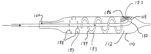
Attention is now drawn to Figures 3A and 3B, which are simplified
schematics illustrating additional alternate constructions for heat exchanging
configurations 170. Figure 3A presents a heat exchanging configuration
wherein a first gas lumen 163 is positioned within a second gas lumen 165, and
the first gas lumen presents fins 176 to enhance heat exchange between the
gasses contained in lumens 163 and 165. As indicated in the figure, such a
heat
exchanging configuration can be implemented with gas input lumen 104 as
inner lumen 163 and exhaust gas lumen 130 as outer lumen 165. As further
CA 02461217 2004-03-22
WO 03/026719 PCT/IL02/00791
34
indicated in the figure, such a heat exchanging configuration can
alternatively
be implemented with exhaust gas lumen 130 as inner lumen 163 and.input gas
lumen 104 as outer lumen 165.
Figure 3B presents yet another heat exchanging configuration, in which,
secondary gas input lumen 177 and a secondary Joule-Thomson orifice 178
have been added to a configuration otherwise similar to that presented in
Figure
3A. The configuration presented by Figure 3B might be used, for example, to
further enhance pre-cooling of cooling gas in gas input lumen 104, by
combining pre-cooling power of cold exhaust gasses from gas exhaust lumen
130 with additional pre-cooling power of additional pressurized cooling gas
supplied through secondary gas input lumen 177 and expanded on passing
through Joule-Thomson orifice 178. Supply of gas to secondary gas input
lumen 177, if used, is preferably controlled through a remotely controlled
valve
under control of control module 150, described in detail hereinbelow.
Heat exchanging configurations as illustrated in Figures 3A and 3B may
optionally be used as heat exchanging configurations 170 presented in Figure
2C, or at other locations within catheter 100 or within a gas supply module
supplying pressurized gas to catheter 100.
In operation of catheter 100, high pressure incoming gas is supplied to
catheter 100 from a gas supply module operable to supply cooling gas and
preferably also operable to supply heating gas. Incoming gas is preferably
initially supplied at or near room temperature, and is preferably supplied at
a
pressure between 2000 to 6000 psi, and most preferably at a pressure between
3000 to 4500 psi. Incoming gas flows through input gas lumen 104 and
expands through the orifice 108 inside the balloon 110.
If the incoming gas is a cooling gas, temperate of this input gas is
reduced drastically through the Joule-Thomson effect as it passes into balloon
110, reaching a temperature preferably between 0 C and -186 C, and more
preferably between -90 C and -140 C. Attainable temperatures on the surface
of balloon 110, in contact with body tissue, are between -10 C and -80 C.
CA 02461217 2004-03-22
WO 03/026719 PCT/IL02/00791
Attainable temperature gradients for freezing and thawing are up to 100 C per
second.
Cold gas having served to cool balloon 110 flows out of balloon 110 and
into gas exhaust lumen 130, where it is preferably used to cool incoming gas
in
5 input gas lumen 104, as described above.
As shown in Figure 2A, gas exhaust control valve 132 is operable to
control pressure of exhaust gasses flowing out of balloon 110. Appropriate
manipulation of valve 132 enables to maintain a desired pressure within
balloon 110, preferably between 3 and 50 atmospheres of pressure, and more
10 preferably between 6 and 27 atmospheres.
Valve 132 may be implemented as a manual valve, yet valve 132 is
preferably implemented as a remotely controlled valve under control of control
system 150. Control system 150 is preferably operable to control flow of
exhaust gas through valve 132. Control system 150 is further operable to
15 control flow of input gasses to balloon 110, as will be shown hereinbelow.
Combined control of input of gas into balloon 110 and output of exhaust gas
from balloon 110 enables control module 150 to establish and maintain a
desired pressure within balloon 110, or indeed to establish an maintain a
desired pressure profile over time, according to a pre-planned treatment
profile
20 or to real-time preferences of an operator responding to real-time
requirements
of a therapeutic procedure.
Attention is now drawn to figures 4A and 4B, which are simplified
schematics illustrating the use of stems with cryocatheter 100, according to
an
embodiment of the present invention.
25 Figure 4A shows a catheter 100 whose balloon 110 is deflated and is
covered by a stmt 174 in collapsed configuration. In a preferred embodiment,
diameter of distal portion 102 of catheter 100, including deflated balloon and
collapsed stmt 174, is not substantially greater than that of flexible tube
160,
enabling distal portion 102 to pass easily along an artery or other body
conduit.
30 As shown in Figure 4B, when distal portion 102 has been appropriately
CA 02461217 2004-03-22
WO 03/026719 PCT/IL02/00791
36
positioned in proximity to tissues to be treated, cooling gasses or other
gasses
may be used to inflate balloon 110, thereby performing angioplasty, optionally
positioning stmt 174 in expanded configuration within an artery or other body
conduit, and optionally cooling surrounding tissues to discourage restenosis.
Balloon 110 is preferably inflated with cooling gasses so as to cool treated
tissues as they are compressed by the angioplasty balloon, yet alternatively
balloon 110 may be inflated with non-cooling gasses or with a liquid.
Similarly, if it is desired to heat balloon 110, for example to facilitate
disengagement of catheter 110, such heating is preferably accomplished by
supplying compressed heating gas through input gas lumen 104 through orifice
108 into balloon 110, yet heating may alternatively be accomplished by
supplying low-pressure pre-heated gasses other than heating gasses, or further
alternatively, heating may be accomplished by supplying a heated liquid
through input lumen 104. - y '-
Attention is now drawn to Figure 5, which is a simplified schematic of a
cryocatheter having a Joule-Thomson orifice shaped and oriented so as to
induce selected patterns of motion in gasses passing therethrough, according
to
an embodiment of the present invention.
As shown in Figure 5, high-pressure gas from gas input lumen 104
passes through Joule-Thomson orifice 108 into balloon 110. Orifice 108 is
formed as a shaped nozzle 180 designed and constructed to induce a selected
form of motion in gas passing therethrough, as indicated by arrows 182.
Shaped nozzle 180 may be oriented in a manner which directs gasses passing
therethrough to circulate within balloon in a circular motion pattern, or
alternately in a manner which directs gasses passing therethrough to circulate
within balloon 110 in a swirling or spiral pattern. Shaped nozzle 180 may, for
example, be placed near an interior wall of balloon 110 and be oriented
tangentially to that wall. Further alternately, shaped nozzle 180 may be
formed
in a shape that deflects gas flow, or nozzle 180 may comprise obstructive
CA 02461217 2004-03-22
WO 03/026719 PCT/IL02/00791
37
shapes which induce turbulence in gasses passing therethrough into balloon
110.
As discussed in the background section hereinabove, one disadvantage
of certain prior art systems is the uneven cooling produced, wherein parts of
an
angioplasty balloon which are proximate to the delivery site of evaporative
cooling fluid tend to be much colder than other areas of that angioplasty
balloon. The configuration illustrated by Figure 5 can be used to reduce or
eliminate uneven cooling, by directing gas cooled by expansion upon exit from
Joule-Thomson orifice 108 to circulate effectively within balloon 110, thereby
enhancing heat transfer between cold gas and interior walls of balloon 110,
thereby contributing to relatively even cooling throughout all of balloon 110.
Alternatively, the configuration illustrated by Figure 5 can be used to
produce intentionally uneven cooling by concentrating cooling within a
selected area of balloon 110. Shaped nozzle 180 can be formed and oriented in
a manner which directs a concentrated flow of cold gas into a selected portion
of balloon 110, thereby enhancing cooling in that selected portion, leaving
higher temperatures in other areas of balloon 110.
Attention is now drawn to Figure 6, which is a simplified schematic of a
cryocatheter comprising a plurality of Joule-Thomson orifices, according to an
embodiment of the present invention. As illustrated in Figure 6, a catheter
100
comprises a plurality of Joule-Thomson orifices 108, some or all of which may
be formed and oriented as shaped nozzles 180 designed and constructed to
induce a selected form of motion in gas passing therethrough. The
configuration presented in Figure 6 may be used to ensure good circulation of
cool gas within balloon 110 so as to enhance even distribution of cooling
throughout balloon 110. Alternatively, a configuration similar to that
presented
in Figure 6, but wherein a plurality of orifices 108 are concentrated in a
selected area of balloon 110 and distanced from other parts of balloon 110,
may
be utilized to concentrate cooling in a selected portion of balloon 110, and
to
lessen the degree of cooling in non-selected portions of balloon 110.
CA 02461217 2004-03-22
WO 03/026719 PCT/IL02/00791
38
Attention is now drawn to Figure 7, which is a simplified schematic of a
cryocatheter comprising flow control structures for directing a flow of gas
within an angioplasty balloon, according to an embodiment of the present
invention. As was shown above with respect to Figures S and 6, selected
number, placement, shape, and orientation of gas delivery orifices 108 can
produce a configuration which enhances even distribution of cooling gas
throughout balloon 110, or alternatively can be used to produce a
configuration
which concentrates cooling in a selected portion of balloon 110. Figure 7
presents an alternative (or complementary) configuration useable to enhance
evenly distributed cooling or, alternatively, to achieve selectively
concentrated
cooling.
Figure 7 presents a catheter 100 wherein interior volume 112 of balloon
110 comprises flow control structures 183 designed and constructed to
influence circulation of moving gasses within volume 112. Several forms of
flow control structures are presented.
Flow directors 184 guide gasses into a desired pattern of motion. For
example, flow directors 184 may be used to enhance circular flow of gas, or
spiral flow of gas.
Multiple internal channels 186 serve to subdivide gas flow.
Spoilers 188 serve to increasing turbulence of circulating gas.
Flow control structures 183 are preferably constructed of material
identical to, or similar to, materials of which balloon 110 is constructed.
Attention is now drawn to Figure 8, which is a simplified schematic of a
cryocatheter 100 comprising two inflatable balloons, according to an
embodiment of the present invention. Figure 8 presents a preferred
embodiment, in which a first inflatable balloon 110 defining a first variable
volume 112 is hermetically contained within a second inflatable balloon 210
defining a second variable volume 212 interior to second inflatable balloon
210
and exterior to first inflatable balloon 110.
CA 02461217 2004-03-22
WO 03/026719 PCT/IL02/00791
39
One possible use of the configuration presented in Figure 8 is to fill or
partially fill second variable volume 212 with a heat-transmitting material,
such
as a liquid, semi-liquid, or gel material, thus producing a configuration
similar
to that described hereinabove with reference to Figure 1B.
In a currently preferred embodiment, volume 212 is not filling with
heat-transmitting material, but rather is left unfilled. A second gas exhaust
lumen 230 in fluid communication with . second variable volume 212 is
operable to exhaust gas from volume 212.
A gas detector 214 is operable to detected presence of gas in volume
212. In use, volume 212 is initially free of gas, and no gas is intentionally
input therein, consequently if gas detector 214 detects presence of gas from
volume 212, such detection may be taken as an indication that pressurized gas
from volume 112 has leaked into volume 212 through a hole or fault in balloon
110. In a preferred implementation, detection of gas under such circumstances
is reported to a control unit 150, which may then undertake such measures as
to
command gas exhaust valve 132 to release pressure from balloon 110,
command a first emergency gas exhaust pump 216 to pump all gas from
balloon 110, command a gas input valve 218 to cease supplying gas to gas
input lumen 104, and command a second emergency gas exhaust pump 217 to
pump all gas from balloon 210. Optionally, first and second emergency gas
exhaust pumps 216 and 217 can be implemented as a single common pump.
Gas detector 214 may be a detector of gas pressure, as used in prior art
devices. Yet in a particularly preferred embodiment of the present invention,
gas detector 214 is a helium gas detector, operable to detect presence of
helium
gas. Helium detectors are available having extreme sensitivity to presence of
even very small quantities of helium gas, even to quantities on the order of
only
a few PPM. Varian Inc., for example, manufactures such a helium detector.
Consequently, use of a helium detector 220 as gas detector 214 has significant
advantages, in that it allows detection of even very tiny leaks in balloon
110,
when balloon 110 contains any concentration of helium gas. Thus, if gas
CA 02461217 2004-03-22
WO 03/026719 PCT/IL02/00791
detector 214 is implemented as helium detector 220, and balloon 110 contains
at least a small concentration of helium gas, the system illustrated by Figure
8
is able to detect and respond to extremely small gas leaks in balloon 110, and
in
particular is able to respond to leaks which would likely go undetected if gas
5 detector 214 were merely a detector of rising gas pressure in volume 212.
Thus, use of helium detector 220 in the configuration presented in Figure 8
contributes significantly to enhancing safety of use of catheter 100. The
configuration presented in Figure 8 may similarly be utilized as a leak
detection
and response system for angioplasty balloon systems incorporating catheters of
10 other types.
The leak detection system illustrated by Figure 8 may be used in a
variety of ways. One preferred method of use is to test catheter 100 prior to
use for angioplasty or cryogenic cooling, by introducing a small amount of
helium gas into balloon 110 prior to inflating balloon 110 with cooling gas or
15 any other fluid. As stated, the extreme sensitivity of available helium
detectors
220 ensures that, if even a small amount of low-pressure helium is introduced
into balloon 110, a fault or leak in balloon 110 will be detectable by
detector
220.
A currently preferred method of maintaining operational safety of
20 catheter 100 is to mix a selected portion of helium gas with cooling gas,
or with
any other fluid used to inflate balloon 110, not only prior to inflating
balloon
110, but also during normal inflation and cooling operations of catheter 100
as
well. According to this preferred method, at least a small amount of helium
gas
is added to whatever cooling gas or other fluid is used to inflate balloon
110.
25 The extreme sensitivity of available helium detectors 220 ensures that even
a
small leak of helium will permit leak detection, even when the amount of
helium added to a fluid (e.g., a cooling gas) supplied to balloon 110 is
sufficiently small to have little or no substantial effect on the gas
temperature
obtained when such a gas mixture passes from a high pressure area to a low
30 pressure area through Joule-Thomson orifice 108. Thus, utilizing a cooling
gas
CA 02461217 2004-03-22
WO 03/026719 PCT/IL02/00791
41
containing at least a small portion of helium gas, and utilizing a helium gas
detector 220 as illustrated, enables to detect leaks or faults in balloon 110
with
a high degree of precision and during the entire course of an angioplasty
and/or
cryoplasty procedure, thus greatly enhancing the safety of such a procedure.
Attention is now drawn to Figure 9, which is a simplified schematic of a
system comprising a cryocatheter and apparatus for controlling operating
temperatures thereof, according to an embodiment of the present invention.
Figure 9 presents a system 90 for angioplastic treatment of arterial
stenosis and for reducing restenosis.
System 90 comprises an angioplasty balloon catheter 100 useable to
treat arterial stenosis, catheter 100 having a gas input lumen 104 for
supplying
a pressurized gas, a first inflatable balloon 110 containing a first variable
volume 112, and a Joule-Thomson orifice 108 for passing pressurized gas from
gas input lumen 104 into first variable volume 112 of first inflatable balloon
110 so as to cool and inflate balloon 110.
System 90 further comprises a supply of compressed cooling gas 232
operable to supply cooling gas to gas input lumen 104, and a cooling gas input
valve 234 controlling delivery of compressed cooling gas from compressed
cooling gas supply 232 to gas input lumen I04.
System 90 further comprises a first gas exhaust lumen 130 for
exhausting gas from first variable volume 112 of balloon 110, and a gas
exhaust valve 132 for controlling passage of gas out of gas exhaust lumen 130.
System 90 further comprises a supply of compressed heating gas 236
operable to supply heating gas to gas input lumen 104, and a heating gas input
valve 238 controlling delivery of compressed heating gas from compressed
heating gas supply 236 to gas input lumen 104.
Gas supplies 232 and 236, input valves 234 and 238, and one-way
valves 240 and 242, together constitute a gas supply module 230. Gas supply
module 230 is operable to supply compressed cooling gas, to supply
compressed heating gas, and to supply a mixture containing both compressed
CA 02461217 2004-03-22
WO 03/026719 PCT/IL02/00791
42
cooling gas and compressed heating gas. Valves 234 and 238 together
constitute a mixed-gas input valve system operable to control delivery of
mixed
gas from gas supply module 230 to gas input lumen 104, and further operable
to control the ratio of cooling gas to heating gas in a mixed gas supplied to
gas
input lumen 104. In an alternative construction, valves 234 and 23 8 may be
combined into a proportional valve governing the proportion of cooling gas to
heating gas delivered to gas input lumen 104.
In an alternative construction, a pre-mixed compressed gas supply 246,
flow from which is controlled by a pre-mixed gas input valve 248, may also
supply gas, through a one-way valve 250, to gas input lumen 104. Pre-mixed
compressed gas supply 246 contains a mixture of cooling gas and heating gas
in selected proportion. Mixed gas supply 246 may be used instead of, or in
conjunction with, cooling gas supply 232 and heating gas supply 236.
Mixing a heating gas, such as helium, with a cooling gas can provide a
useful service, over an above the gas-leak detection service described
hereinabove with reference to Figure 8. As mentioned in the background
section hereinabove, in various surgical procedures, and particularly in
treatment of arterial stenosis, optimal temperature for treatment of afflicted
tissues can be somewhat less cold than the maximum cooling temperature
which can be achieved by a cryocatheter cooled by Joule-Thomson cooling. In
practice, it is desirable that a surgeon be enabled to exercise control over
the
operating temperature of catheter 100, so that he or she can select an
appropriate temperature for each therapeutic situation. Indeed, it is further
desirable to enable a surgeon to specify a temperature profile defined over
time, permitting him or her to specify, for example, an initial temperature to
be
maintained during a first selected period, followed by a second temperature to
be maintained during a second selected period, perhaps followed by a heating
cycle used during disengagement of catheter 100.
It is noted that gas supply module 230, operable to supply a mixture of
heating and cooling gas, is operable to supply a gas having a mixture of
heating
CA 02461217 2004-03-22
WO 03/026719 PCT/IL02/00791
43
and cooling gasses selected in such proportion that little or no substantial
heating or cooling effect results when a compressed gas mixture so selected
passes through a Joule-Thomson orifice. Gas supply module 230 can thus be
used to provide a gas operable to inflate balloon 110 without significantly
heating it nor cooling it. According to a preferred embodiment of the present
invention, system 90 is operable to supply such a non-heating non-cooling
mixture to balloon 110 during a first time, so as to perform angioplasty
without
cooling, and then subsequently to supply a cooling gas mixture to balloon 110
during a second time, so as to cool treated tissues subsequent to, rather than
simultaneously with, compression of those tissues by angioplasty. Of course,
in alternate preferred embodiments, cooling and angioplasty may be practiced
simultaneously, as variously described herein.
It is to be noted that various valves illustrated in Figure 9 as controlling
gas flow into and out of balloon 110 are preferably remotely controllable by
commands from control module 150. Gas exhaust valve 132, useable to
control gas flow through gas exhaust lumen 130, is preferably controllable by
control module 150. Cooling gas input valve 234 controlling flow of cooling
gas from gas supply module 230, and heating gas input valve 238 controlling
gas flow from heating gas source 236, are preferably controllable by control
module 150. Thus, flow of gas passed by cooling gas input valve 234 and
one-way valve 240, through gas input lumen 104 and thence through orifice
108 into balloon 110, and flow of gas passed by heating gas input valve 236
and one-way valve 242, through gas input lumen 104 and thence through
orifice 108 into balloon 110, are both controllable by control module 150.
Control module 150 is preferably operable to control input valves 234
and 238 according to operator commands, or alternatively according to
programmed commands stored in a memory, or further alternatively according
to algorithmic calculations made according to programmed commands and
applied to data received from sensors such as sensors 140.
CA 02461217 2004-03-22
WO 03/026719 PCT/IL02/00791
44
Thus, gas supply module 230 is operable to supply cooling gas to gas
input lumen 104 when so desired, and to supply heating gas to gas input lumen
104 when so desired. A gas input module so configured is well known in
cryosurgery practice, where it has typically been used to provide alternating
cooling and heating to cryoprobes in cryoablation systems, where it accepted
practice to cool a probe to effect cryoablation, and subsequently to heat that
probe after cryoablation to free it from tissues to which a freezing process
has
caused it to adhere.
The configuration presented in Figure 9 enables, however, a new and
different use of gas supply module 230. According to a preferred method of
operation of the configuration here presented, cooling gas input valve 234 and
~r.
heating gas input valve 238 are operable to provide both cooling gas and
heating gas to input gas lumen 104 simultaneously or nearly simultaneously, so
as to obtain in input gas lumen 104 a mixture 244, which mixture is comprised
of cooling and heating gasses in selected proportion. The effect of passing
such pressurized mixture 244 of heating and cooling gasses through orifice 108
is to produce a cooling or heating effect in which the degree of cooling or of
heating obtained is finely controllable. Increasing the proportion of cooling
gas
in mixture 244 will increase the cooling effect. Decreasing the proportion of
cooling gas in mixture 244 will decrease the cooling effect.
Management of mixture 244 is preferably controlled by control module
150, issuing commands to valves 234, 238, and optionally 248, which
commands are determined under algorithmic control based on calculations
made on a basis of data in form of real-time temperature information received
from one or more heat sensors 140 positioned within balloon 110, or positioned
in other portions of the body of catheter 100, or positioned in tissue areas
proximate to catheter 100, and optionally further based on data from pressure
sensors 141 placed in various positions within system 90.
Control module 150 can thus operate a feedback control cycle, in which
temperature changes registered by sensors 140 and reported to control module
CA 02461217 2004-03-22
WO 03/026719 PCT/IL02/00791
150 cause control module 1 SO to command changes in relative amounts of gas
passed by cooling gas valve 234 and heating gas valve 238, thereby enabling
control module 150 to establish fine control of temperatures in and around
catheter 100 during operation.
S It is to be noted that system 90 enables fine control of temperature,
which control is relatively independent of quantities of gas passing orifice
108,
in that a desired cooling effect can be created by using a relatively small
gas
flow composed preponderantly of cooling gas, or by using a relatively large
flow of gas composed of relatively less cooling gas and somewhat more
10 heating gas.
This relative independence of the cooling effect from the absolute
amount of gas flow is particularly useful in the context of angioplastic
therapy,
since it enables a surgeon, preferably through use of control services
provided
by control module 150, to independently manipulate pressure maintained in
15 _ balloon 110 on the one hand, and temperature maintained in balloon 110 on
the
other hand.
Control module 150 provides various control and monitoring functions
for the system presented in Figure 9. Control module 150 preferably comprises
a data collection unit 260 for receiving data generated by at least one sensor
20 positioned in or near a distal portion of catheter 100, such as thermal
sensors
140 and pressure sensors 141. Control module 150 preferably further
comprises a processing unit 262 for evaluating data received by data
collection
unit 260 according to a stored algorithm 264, and a command module 265 for
sending commands to one or more remotely controlled gas flow valves, such as
25 valves 234, 248,238, and 132.
Processing unit 262 preferably comprises a processor 266 and a memory
268, memory 268 being operable to record at least a portion of data received
by
data collection unit 260. Processing unit 262 optionally comprises a display
270 operable to display functional data received by data collection unit 260.
CA 02461217 2004-03-22
WO 03/026719 PCT/IL02/00791
46
Processing unit 262 is preferably designed and constructed to respond to
received data, to evaluate it under algorithmic control, to generate commands
based on these algorithmically controlled evaluations, and to send commands
so generated to valves 234, 248, 238, 132, and to other valves and remotely
controllable units within system 90.
As described hereinabove, in a preferred embodiment control unit 150 is
operable to substantially maintain a portion of catheter 100 near a selected
temperature, by sending appropriate commands to at least one, and preferably
more than one, gas flow control valve, using commands chosen according to an
algorithm in response to data received from sensor 140, and preferably from a
plurality of sensors, including thermal sensors and pressure sensors.
In an optional preferred embodiment, system 90 may be implemented
utilizing as catheter 100 a double-balloon catheter such as that discussed
hereinabove with reference to Figure 8. In such an embodiment, gas detector
214 (preferably helium detector 220), integrated into system 90, is operable
to
report detection of gas (preferably detection of helium) to control module
150.
Command module 150, upon receipt of a report of gas detection by detector
214, is operable to command actions by emergency vacuum pumps 216 and
217 and gas input valve 218, according to a programmed response pattern.
In an additional optional preferred embodiment, system 90 may also be
implemented utilizing, in place of cryocatheter 100, a cryoablation probe
designed and constructed for cryoablation of tumors. A system so constructed,
utilizing mixed gas 244 to provide fine control of degree of cooling as
explained hereinabove, may be used to advantage in cryoablation applications
in which less-than-maximal cooling of a cryoprobe is desired for clinical
reasons.
Attention is now drawn to Figure 10, which is a simplified schematic
presenting an embodiment of system 90 comprising a double-balloon catheter
100, and apparatus for detecting and for responding to gas leaks in inner
balloon 110. The system presented in Figure 10 may be seen to include the
CA 02461217 2004-03-22
WO 03/026719 PCT/IL02/00791
47
various characteristics of system 90 as described hereinabove with respect to
Figure 9, and to further included the double-balloon catheter, gas leak
detection
mechanism, and gas leak response apparatus described hereinabove with
respect to Figure 8.
S Attention is now drawn to Figure 11, which is a simplified schematic
presenting an optional alternate construction for system 90, according to an
embodiment of the present invention. The system illustrated in Figure 11 is
distinguished by the presence of heat exchanging configurations 170 in a
plurality of functional positions within the system.
In Figure 11, system 90 has been conceptually subdivided into one
external and three internal units.
Gas supply module 230, containing mechanisms for gas supply and gas
input control, for helium detection and leak control, and for emergency vacuum
pumping, is external to the patient's body.
1 S Catheter 100, designed for insertion into the body, is conceptually
divided into three sections. Endovascular-precoronary section 280 comprises
flexible tube 160, designed to be flexibly inserted into a blood vessel or
other
bodily conduit of a patient. Coronary section 282, preferably about 25 cm in
length, is designed to enter the coronary region of the body during an
angioplasty procedure. Distal portion 102 consists primarily of inflatable
balloon 110, and optional second inflatable balloon 210.
As shown in Figure 10, heat exchanging configurations 170 may be
utilized in various areas, to enhance the efficiency with which cryogenic
cooling is accomplished. Heat exchanging configuration 170A is placed at a
point of transition between coronary section 282 and distal portion 102. Heat
exchanging configuration 170B is placed at a point of transition between
coronary section 282 and endovascular-precoronary section 280. Other
emplacements for heat exchanging configurations 170, within sections 280,
282 and 102, may also be used.
CA 02461217 2004-03-22
WO 03/026719 PCT/IL02/00791
48
Another optional placement for a heat exchanging configuration 170 is
shown in Figure 11 as heat exchanging configuration 170C. Heat exchanging
configuration 170C is an integrated component of gas supply module 230, and
thus is positioned outside the body during operation.
Each of the heat exchanging configurations 170A, 170B, and 170C is
operable to exchange heat between exhaust gas from exhaust gas lumen 130
and input gas within, or flowing towards, input gas lumen 104. Additional
heating and cooling systems may be utilized in addition to, or in place of,
one
or more heat exchanging configurations 170. In particular, a pre-cooling
system 171 may be used in addition to, or in place of, heat exchanging
configuration 170C, within gas supply module 230, utilizing electrical
cooling,
a closed refrigeration cycle, a liquid nitrogen bath, liquid nitrogen
secondary
flow, or other similar methods.
Alternate gas heating methods may also be used to provide heat to
catheter 100. An electrically heated low-pressure gas supply 173 may be so
used. Units 171 and 173, if used, are preferably controlled by control unit
150.
Optional high-pressure vent 286 is provided, preferably near a coupling
between gas supply module 230 and cryocatheter 100, for selectively venting
gas from input lumen 104. Use of vent 286 may be useful in a variety of
circumstances. During an emergency such as detection of a gas leak in balloon
110, it may be desirable to immediately reduce pressure in balloon 110.
Additionally, a desired rapid change of operating temperature within balloon
110, for example a change from a cooling phase of operation to a heating phase
of operation, is best accomplished by venting pressurized gas of one type
(e.g.,
cooling gas) in input lumen 104, before starting to supply gas of a second
type
(e.g., heating gas) to input lumen 104. High-pressure vent 286 is preferably
controlled by control module 150.
Each heat exchanging configuration 170 is preferably equipped with a
thermal sensor 140 operable to report operating temperatures to control module
150. Additional thermal sensors 140 may be positioned at other sites within
CA 02461217 2004-03-22
WO 03/026719 PCT/IL02/00791
49
catheter 100, or indeed at additional sites external to catheter 100, such as
within gas supply module 230, or. within body tissues of a patient in
proximity
to catheter 100.
Attention is now drawn to Figure 12, which presents an additional
S alternate configuration for system 90. Figure 12 features separate heat
exchanging configurations 170D and 170E in place of heat exchanging
configuration 170C of Figure 11. Heat exchanging configuration 170D is
operable to pre-cool cooling gas from cooling gas supply 232 on its way to
input gas lumen 104, preferably using exhausted cold gas from gas exhaust
lumen 130. Heat exchanging configuration 170E is operable to pre-heat
heating gas from heating gas supply 236 on its way to input gas lumen 104,
using exhausted hot gas from gas exhaust lumen 130. Heat exchanging
configurations 170D and 170E may optionally be constructed according to
configurations described hereinabove with reference to Figures 3A and 3B.
1 S Input valves controlling input of cooling gas may be placed at position
234A or at position 234B, or in both positions. Input valves controlling input
of heating gas may be placed at position 238A or at position 238B, or in both
positions.
The configuration presented by Figure 12 is useful because efficient heat
exchange, in heat exchanging configurations 170C, 170D, and 170E, requires a
relatively large internal volume of gas within those heat exchanging
configurations. Using a common heat exchanging configuration 170C both to
pre-cool cooling gas and to pre-heat heating gas, as is done in the
configuration
presented by Figure 11, has an effect of reducing speed of response of system
90 to a change from a first gas input (e.g., cooling gas) to a second gas
input
(e.g., heating gas), since a relatively large volume of a first gas must be
flushed
from heat exchanging configuration 170C before heat exchanging
configuration 170C can be entirely filled with, and dedicated to the pre-
cooling
or pre-heating of, an intended second gas.
CA 02461217 2004-03-22
WO 03/026719 PCT/IL02/00791
A more rapid response to a change from cooling to heating, or from
heating to cooling, maybe obtained from the configuration presented in Figure
12, wherein each gas source has a dedicated heat exchanging configuration,
170D dedicated to pre-cooling cooling gas, and 170E dedicated to pre-heating
5 heating gas. Input valves 234A and/or 234B and 238A and/or 238B need
merely be closed and opened appropriately, to produce an almost immediate
response from gas supply module 230, with no delay required for flushing the
system of inappropriate gas.
Attention is now drawn to Figure 13, which is a simplified schematic
10 presenting additional features of a cryocatheter according to an embodiment
of
the present invention.
Figure 13 presents a catheter 100 comprising an optional injection lumen
290 suitable for injecting a material near distal portion 102 of catheter 100.
Injection lumen 290 is useful for injecting, for example, a contrast imaging
15 material into are area near a treatment site, to facilitate imaging of that
site,
thereby facilitating correct placement of catheter 100 for treatment, or
thereby
facilitating evaluation of an ongoing or completed angioplasty procedure.
Figure 13 further presents a guide-wire lumen 292 for enabling and
guiding passage of a guide wire through a length of catheter 100. According to
20 a common surgical practice, a guide wire is often used to guide insertion
of an
angioplasty catheter during an angioplasty procedure. Guide wire lumen 292
serves to permit passage of a guide wire 294 along an internal length of
catheter 100, providing compatibility with standard wire-guided angioplasty
procedures.
25 Attention is now drawn to Figure 14, which is a simplified schematic
presenting an alternate positioning for a guide wire lumen within a
cryocatheter, according to an embodiment of the present invention. Whereas
guide wire lumen 292 presented in Figure 13 is centered within catheter 100
and particularly within balloon 110, circumferential guide wire lumen 296
30 presented in Figure I4 has a circumferential positioning within balloon
110.
CA 02461217 2004-03-22
WO 03/026719 PCT/IL02/00791
51
Such circumferential positioning permits guide wire lumen 296, and within it
guide wire 294, to be embedded within wall 114 of balloon 110, for example
between adjacent layers of material forming wall 114.
Attention is now drawn to Figures 15A, 15B, and 15C, which illustrate
in simplified form clinical findings of a relationship often found to obtain
between temperature of tissues lining a coronary artery and stenotic narrowing
of arteries due to plaque.
Figure 15A schematically illustrates a section of coronary artery 308 in
which blood flow is impeded by a narrowing, caused by plaque 312.
Figure 15B presents a temperature graph 314 of coronary artery section
308, where temperature is plotted on a vertical axis against position plotted
on
a horizontal axis, the horizontal axis being common to Figures 15A, 15B, and
15C. Figure 15B presents a well-known clinical finding, that areas narrowed
by plaque tend to have a higher temperature than other, healthier, areas
within a
same arterial section. This temperature differential, apparently resulting
from
an inflamed state of tissues at the site of the restriction, may be used to
localize
that restriction for treatment. Figure 15C shows a balloon catheter (e.g.,
catheter 100) appropriately positioned for treating the condition seen in
Figure
1 SA and localized by temperature chart 1 SB.
Attention is now drawn to Figure 16, which is a simplified schematic of
an angioplasty balloon catheter comprising a plurality of external temperature
sensors located along a selected section thereof, according to an embodiment
of
the present invention.
In Figure 16, angioplasty balloon catheter 300 comprises an inflatable
balloon 310 operable to perform angioplasty, and a plurality of temperature
sensors 320 (also called "thermal sensors" and "heat sensors" in the
following)
arranged along a selected section of catheter 300. Catheter 300 may have the
characteristics of catheter 100 described hereinabove, or alternatively may be
a
cryogenic balloon catheter coolable using methods of prior art, or further
alternatively may be a cryogenic balloon catheter coolable using other methods
CA 02461217 2004-03-22
WO 03/026719 PCT/IL02/00791
52
of cooling, or yet further alternatively catheter 300 may be an angioplastic
balloon catheter not comprising mechanisms for cooling balloon 310.
Temperature sensors 320 may be thermocouples 322, or thermographic
camera sensors 324, or fiber-optic fibers 326 operable to transmit infra-red
light from a tissue site to a thermographic camera sensor 324 external to
catheter 300, or any other sensor operable to report temperatures in a
vicinity of
body tissues in proximity to catheter 300, when catheter 300 is inserted in an
artery or other body conduit.
Attention is now drawn to Figure 17, which presents an expanded view
of a section of the catheter presented in Figure 16, showing in greater detail
a
plurality of heat sensors placed along an external length of that catheter,
according to an embodiment of the present invention. In an optional
embodiment shown in Figure 17, heat sensors 320 are shown to be linked by a
data link 328, which may be a wire or bundle of wires operable to connect
thermocouples 322 to an outside data receiver such as control module 150
described hereinabove. Data link 328 may also be a bundle of fiber-optic
fibers
326, or any other sort of data communicator. Sensors may also be linked to an
outside data collector such as control module 150 using a wireless
communicator 329.
Attention is now drawn to Figure 18, which presents recommended
dimensions for various parts of an angioplasty balloon catheter comprising a
plurality of external thermal sensors along a selected section thereof,
according
to a preferred embodiment of the present invention. The dimensions provided
in Figure 18 are presently recommended dimensions for a catheter combining
the characteristics of catheter 100 and catheter 300, both defined and
described
hereinabove.
Attention is now drawn to Figure 19, which is a simplified schematic
presenting an alternate scheme of placement for thermal sensors along a
section
of an angioplasty balloon catheter, according to an embodiment of the present
invention. Figure 19 presents a section of catheter similar to that presented
in
CA 02461217 2004-03-22
WO 03/026719 PCT/IL02/00791
53
Figure 17, with the difference that in an alternative construction presented
in
Figure 19, thermal sensors 320 are spirally positioned around and along a
selected segment of catheter 300, thus enabling temperature readings an all
sides of catheter 300 along that selected length of catheter 300.
Attention is now draw to Figure 20, which is a simplified schematic
presenting an alternate design for thermal sensors along a section of an
angioplasty balloon catheter, according to an embodiment of the present
invention. Figure 20 presents a section of catheter similar to that presented
in
Figure 19, with the difference that in an alternative construction presented
in
Figure 20, thermal sensors 320 comprise a hair-like fiber 330 designed and
constructed to facilitate transfer of heat between thermal sensors 320 and
body
tissues surrounding catheter 300 and adjacent to thermal sensors 320. Hair-
like
fibers 330 extend slightly outward from catheter 300, and thus are able to
make
physical contact with surrounding tissues, such as with portions of an
arterial
wall, when catheter 300 is inserted in an artery. Such contact enhances
accuracy of temperature readings from sensors 320, in that such contact
enhances ability of sensors 320 to report temperature of arterial wall
tissues, as
opposed, say, to temperature of blood flowing in an artery in which catheter
300 has been inserted.
Attention is now drawn to Figure 21, which is a simplified schematic
presenting a further alternate design for thermal sensors along a section of
an
angioplasty balloon catheter, according to an embodiment of the present
invention. Figure 21 presents a section 340 of angioplasty balloon catheter
300, section 340 comprising an internal shaft 342 and an external mufti-sensor
thermal sensing device 350.
Shaft 342 is preferably a flexible tube. If catheter 300 is formed as
catheter 100 described hereinabove, then shaft 342 will contain input gas
lumen
104, exhaust gas lumen 130, and may contain various other optional features
heretofore described.
CA 02461217 2004-03-22
WO 03/026719 PCT/IL02/00791
54
Mufti-sensor thermal sensing device 350 comprises a laterally
contracting spring-like structure 344, preferably of spiral form, wrapped
around
shaft 342. Sensing device 350, preferably formed as a spiral sensing loop,
further comprises a plurality of individually readable heat sensors 320,
sensors
320 being substantially similar to heat sensors 320 previously described with
reference to Figures 16, 17, 19, and 20.
Laterally contracting spring-like structure 344 is preferably anchored at
its distal end to a fixed position 346 on shaft 342, whereas a proximal end of
structure 344 is free to move longitudinally along shaft 342. In its relaxed
position, laterally contracting spring-like structure 344 is designed and
constructed to lie closely adjacent to shaft 342, as is shown in Figure 21.
Thus
positioned, sensing device 350 does not add substantially to the diameter of
catheter 300, and thus leaves catheter 300 free to move forward and backwards
within an artery or other body conduit. With structure 344 positioned as
depicted in Figure 21, catheter 300, together with mufti-sensor thermal
sensing
device 350, is free to move within arterial walls 348.
Attention is now drawn to Figure 22, which is a simplified schematic of
the apparatus of Figure 21, shown in expanded position. Structure 344 is so
designed that when longitudinal pressure is applied to the proximal end of
structure 344, towards fixed position 346, structure 344 is forced to expand,
in
spring-like manner, away from shaft 342. A movement of expansion thus
engendered forces structure 344 into contact with arterial walls 348
surrounding catheter 300, as is shown in figure 22. Sensors 320 positioned
along the length of structure 344 are thus forced into contact, or into close
proximity, with body tissues lining arterial walls 348. Such contact or
proximity enhances transfer of heat from those body tissues to sensors 320,
thereby enhancing accuracy of thermal sensing by sensors 320.
Attention is now drawn to Figures 23 and 24, which show a slightly
altered construction for mufti-sensor thermal sensing device 350, according to
a
preferred embodiment of the present invention.
CA 02461217 2004-03-22
WO 03/026719 PCT/IL02/00791
Design and construction of sensing device 350 as shown in Figures 23
and 24 is identical to that shown in Figures 21 and 22, with the exception
that a
spiral sensing loop formed as a laterally expanding spring-like structure 354
is
substituted, in Figures 23 and 24, for a spiral sensing loop formed as
laterally
5 contracting spring-like structure 344 of Figures 21' and 22. Laterally
expanding
spring-like structure 354 is so constructed that in its relaxed state
structure 354
tends to expand away from shaft 342, as shown in Figure 24. A pulling
attachment 352 is provided for pulling a proximal end of structure 354 away
from a distal end of structure 354 anchored at position 346.
10 As shown in Figure 23, during introduction of catheter 300 into an artery
or other body conduit, pulling attachment 352 is pulled away from anchored
position 346, thereby stretching structure 344 along shaft 342, thereby
minimizing distance between device 350 and shaft 342, thereby facilitating
movement of catheter 300 along an artery or other body cavity and minimizing
15 friction or other interference between catheter 300 and arterial walls 348.
When catheter 300 is thought by an operator to be positioned in the
vicinity of a lesion, pulling attachment 352 is released, allowing laterally
expanding spring-like structure 354 to expand to its relaxed position, as
shown
in Figure 24. As may be seen in the figure, structure 354 in its relaxed state
20 tends to bring sensors 320 into close proximity to, or into contact with,
body
tissues surrounding catheter 300, such as arterial walls 348. Transfer of heat
between arterial walls 348 and sensors 320 is thereby enhanced, thereby
enabling device 350 to accurately sense and report temperatures at or near
those body tissues.
25 Thus, to summarize Figures 21, 22, 23, and 24, each of the figures
represents a catheter 300 having a plurality of thermal sensors distributed
along
an expandable spiral sensing loop having a distal end anchored to a distal
portion of catheter 300. This expandable spiral sensing loop is spirally wound
around a section of shaft of catheter 300, and is operable to expand away from
30 that shaft, thereby enhancing thermal communication between sensors
CA 02461217 2004-03-22
WO 03/026719 PCT/IL02/00791
56
distributed along that sensing loop and body tissues adjacent to catheter 300.
In the configuration presented by Figures 21 and 22, spiral sensing loop 344
is
designed and constructed to expand away from said shaft of catheter 300 when
a proximal end of that sensing loop is pushed toward an anchored distal end of
that sensing loop. In the configuration presented by Figures 23 and 24, a
spiral
sensing loop is designed and constructed to contract toward a shaft of
catheter
300 when a proximal end of that sensing loop is pulled away from an anchored
distal end of that sensing loop.
Attention is now drawn to Figure 25, which presents yet another
alternative construction for a section of an angioplasty balloon catheter
enabling multiple temperature measurements along a selected section of an
artery, such temperature measurements being useable to assist in locating a
site
for angioplasty. In Figure 25, a catheter 360 comprises a thermal sensor 320A
attached to a moveable base 362, said moveable base being movably mounted
on (and preferably mounted around) a shaft 342. A flexible yet semi-rigid
push-pull connector 364 extends along a length of shaft 362, and may pass
within a plurality of optional guides 366 which serve to maintain connector
364
adjacent to shaft 342. In use, an operator, either manually or utilizing a
servomotor, causes 364 to push or pull base 362, causing base 362, and with it
sensor 320, to slide along shaft 342. In use, heat sensor 320A is used to
register temperature of tissues at a plurality of positions along a selected
length
of catheter 360, thus achieving a plurality of temperature measurements
utilizing a single moveable heat sensor 320A (or alternatively, a small number
of sensors 320) in place of a plurality of heat sensors 320 as was described
above with reference to Figures 16-24. Thus, catheter 360 may be used in
much the same way as catheter 300. In a preferred embodiment, sensor 320A
is a fiber optic element moveable along catheter 360 and connectable to a
thermographic camera 370 external to catheter 360.
Temperature-sensing apparatus described hereinabove with reference to
Figures 16-17 and Figures 19-25 is particularly useful in positioning an
CA 02461217 2004-03-22
WO 03/026719 PCT/IL02/00791
57
angioplasty balloon catheter for an angioplasty procedure. A recommended
procedure comprises
a) introducing into an artery the angioplasty balloon catheter, the
angioplasty balloon catheter having an inflatable balloon operable to perform
angioplasty and a plurality of temperature sensors arranged along a selected
section of the catheter,
b) manipulating the catheter into a selected segment of the artery
suspected of having an afflicted portion,
c) operating the temperature sensors to determine temperatures at a
plurality of sites along a selected segment of the artery,
d) comparing the resultant temperature readings to determine a
locus, within the inspected section of the artery, having temperatures high
than
those measured within other portions of the artery, and
e) further manipulating the catheter so as to position the angioplasty
balloon in a vicinity of that determined locus.
The procedure here described may be used to accurately positioning the
angioplasty balloon of an angioplasty balloon catheter for an angioplasty
procedure.
Similarly, use of temperature-sensing apparatus described hereinabove
with reference to Figures 16-17 and Figures 19-24 enables a recommended
method of treating a stenotic inflammation of an artery, the method
comprising:
a) introducing into an artery an angioplasty balloon catheter such as
catheter 300 described hereinabove, having an inflatable balloon 310 operable
to perform angioplasty and a plurality of temperature sensors 320 arranged
along a selected section of catheter 310,
b) manipulating catheter 310 into a selected segment of an artery
suspected of having an inflamed portion,
c) operating temperature sensors 320 to determine temperatures at a
plurality of sites along a selected segment of the artery,
CA 02461217 2004-03-22
WO 03/026719 PCT/IL02/00791
58
d) comparing temperature readings to determine a locus, within the
selection section of the artery, having a temperatures high than those
measured
within other portions of the artery,
e) further manipulating catheter 300 so as to position balloon 310 in
a vicinity of the locus determined in step (d), and
f) inflating balloon 310 so as to compress tissues around balloon
310 at the determined locus, thereby performing angioplasty,
thereby treating said stenotic inflammation of said body conduit.
In a particularly recommended procedure, the above method of treating
a stenotic inflammation of an artery comprises an additional step, namely
utilizing a balloon catheter 300 equipped for cryogenic cooling of balloon 310
to cool balloon 310, and tissues surrounding balloon 310, during or
immediately after angioplasty.
In a further recommended procedure, catheter 300 is implemented as
1 S catheter 100 described hereinabove, and cooling of inflated balloon 310
(also
identifiable as balloon 110 described hereinabove) is accomplished using
Joule-Thomson cooling of cooling gas introduced under pressure to a
Joule-Thomson orifice (orifice 108) within balloon 310.
It is appreciated that certain features of the invention, which are, for
clarity, described in the context of separate embodiments, may also be
provided
in combination in a single embodiment. Conversely, various features of the
invention, which are, for brevity, described in the context of a single
embodiment, may also be provided separately or in any suitable
subcombination.
Although the invention has been described in conjunction with specific
embodiments thereof, it is evident that many alternatives, modifications and
variations will be apparent to those skilled in the art. Accordingly, it is
intended to embrace all such alternatives, modifications and variations that
fall
within the spirit and broad scope of the appended claims. All publications,
patents and patent applications mentioned in this specification are herein
CA 02461217 2004-03-22
WO 03/026719 PCT/IL02/00791
59
incorporated in their entirety by reference into the specification, to the
same
extent as if each individual publication, patent or patent application was
specifically and individually indicated to be incorporated herein by
reference.
In addition, citation or identification of any reference in this application
shall
not be construed as an admission that such reference is available as prior art
to
the present invention.