Note: Descriptions are shown in the official language in which they were submitted.
CA 02461325 2004-03-16
f-n G '~ 2 E ~7 ~~7
INTAKE Al'P.~tA.TIL3S FOR J~N~INIE
BACKGROUND OF TbTE INVENTION
l, Field of the Invention
The present invention relates to an intake apparatus fox an engine for a
vehicle.
The present invention is particularly suitable for use in a vehicle such as a
motorcycle.
2_ Descziption of the Related Art
'Various intake apparatuses have been used with vehicles. For example,
Japanese Patent Laid-Open No. 2001-73810 describes a conventional air cleaner
that is
arranged behind a head pipe provided in a firont end of a motorcycle frame. An
intake
duct that extends forward from the air cleaner is arranged below the head
pipe.
However, conventional intake apparatuses have several disadvantages. It is
desirable
to shorten an intake duct in order to effectively introduce moving air into an
air cleaner.
At the same time, it is desirable to increase the opening azea of the intake
duct in order
to increase the available power of the engine. However, water splashed by a
front
wheel or other foreign objects can enter the air cleaner and cause various
problems.
Accordingly, it is desirable to provide an intake apparatus that solves these
problems.
SLfMMARY OF TBE 1NY.ENTION
In one aspect of the invention, au intake apparatus of an engine for a vehicle
is
provided: The intake apparatus is capable of taking in a larger amount of
intake air
when the engine rotates at a high speed as compared with when the engine
rotates at a
low speed, while being configured to mirurnize the entry of water splashed by
a front
wheel and or other foreign objects, such as small rocks or other road debris,
into the air
cleanei .
In one aspect of the invention, when the engine E operates at low speed, that
is,
whets running the small vehicle at low speed because of a roadway where water
is prone
CA 02461325 2004-03-16
to be splashed and a foreign object is prone to be zicocheted, the first
intake passage
arranged on the centerline in the width direction of the fxant wheel is
closed.
Accordingly, the water and the foreign objects can be largely prevented from
entering
the air cleaner. Moreover, when the engine mtates at high speed, it is
difficult for the
water to be splashed upward and for the foreign objects to be ricocheted upe~-
ard due to
a moving air from the front of the vehicle, and accordingly, the water and the
foreign
objects can be prevented from entering the air cleaner as much as possible.
Furthczrnore, the first intake passage of which flow area is large opens to
introduce air
of a relatively large volume into the air cleaner, thus making it possible to
contribute to
an increase in engine power.
rn another embodiment of the present invention, an intake amount is restricted
to be small when the engine operates at low speed, and thus it is possible to
obtain good
acceleration performance by supplying appropriately rich xnixtuze to the
engine while
restricting the mixture from leaning also at the time of an acceleration
operarion.
Moreover; volume efficiency of the engine is enhanced by reducing intake
resistance
when the engine operates at high speed, thus making it possible to contribute
to
enhancement of engine performance, Zn addition, the first intake control valve
and the
second intake control valve can be driven to open and close by iotalionally
driving the
one valve shaft, and accordingly, the structure is made simple.
In another embodiment of the invention, an azrangement is provided so that
when external air is introduced from the second intake passage into the sir
cleaner, the
water and the foreign objects can be prevented from entezing the second intake
passage
as much as possible due to a labyrinth structure of a baffle board.
ru yet another ernboditnent of the invention, an arrangement is provided so
that
when the engine rotates at high speed, moving air is introduced into the first
intake
passage efficiently, and thus intake e~eiency can be enhanced. Moreover, it is
made
possible to make it difficult for the foreign object and the water to enter
the second
2
CA 02461325 2004-03-16
intake passage int7roducing the air therethrough when the engine rotates at
Iow speed.
Ln another embodiment of the invention, an arrangement is provided so that in
a
space between the radiator and the continuous portion of the head pipe and
both main.
frames; the intake duct can be effectively arranged while enlarging an opening
portion
of the front end portion thereof Furthermore, an actuator mounted on the small
vehicle in order to drive an operating member controlled in response to the
number of
revolutions of the engine is connected to the intake control valve in order to
drive the
intake control valve to open and close. With such a constitution, the intake
control
valve can be driven while avoiding an increase of the number of parts and
achieving a
downsizing and weight reduction of the intake apparatus.
In another embodiment of the invention, an ana.ngement is provided so that a
first intake control valve is faced to a valve shaft having an axis orthogonal
to a flowing
direction of air flowing through the first intake passage and xutatably
supported in the
intake duct in a manner of having a posture tilted rearVVard acrd upward in a
state of
closing; the first intake passage. With such a constitution, though the water
splashed by
the front wheel and the foreign objects ricocheted thereby are prone to enter
an upper
portion in the front end opening portion of the first intake passage. When the
intake
control valve starts to operate from a valve closing state thereof to a valve
opening side,
it is facilitated for the splashed water and the ricocheted foreign objects to
eoilide with
the intake control valve even if the splashed water and the bounded foreign
object enter
the front end opening end of the first intake passage. Thus, arc advantage is
brought in
terms of preventing the entry of the water and foreign object to the air
cleaner side.
Moreover, a first intake control valve can be formed such that, in a valve
closing state
'thereof, an area of a poztion above the valve shaft is set larger than an
area of a portion
below the valve shaft. With such a constitution, a greater advantage is
provided in
terms of preventing the entry of the foreign objects to the first intake
passage.
In another embodiment of the invention, an arrangement is provided in which
3
CA 02461325 2004-03-16
an air intake passage of an air cleaner (for example, an air cleaner S7 in an
embodiment)
interposed in an intake system of the engine (for example, an engine E in the
embodiment) is made to face forward in a vehicle, characterized in that at
least tvvo of
the air intake passages, one large and one small, are provided. The large air
intake
passage (for example, a first intake passage I 19 in the embodiment) opens
when the
engine rotates at high speed, the other air intake passage (for example,
second intake
passages 120 in the embodiment) is always closed, and in the other rotation
range, an
opening and closing order is reversed.
By such arrangement, when the large air intake passage opens with the engine
rotating at the high speed, the ram pressure can be effectively utilized. At
that tune,
the other nix intake passage is closed, thus making it possible to prevent
entry of the
mater and foreign objects fram the other air intake passage.
In another embodiment of the invention, an arrangement is provided so that the
two large and smaD air intake passages are arranged in line in a width
direction of the
vehicle. By such arrangement, it is made possible that the two air intake
passages take
in the air without being mutually adversely affected.
In another embodiment of the invention, an amngement is provided so that an
air intake passage of an air cleaner interposed in an ~atake system of the
engine is made
to face forwazd of a vehicle, with at least three of the air intake passages
arranged in Line
in a width direction of the vehicle. By this arrangernenfi, it is made
possible ro arzange
the air intake passage on the center and at least two of the air intake
passages in a
manner of being distributed on the both sides thereof
In another embodiment of the invention, an arrangement is provided so that an
sir intake passage of an air cleaner, interposed zu art antake system of the
engive, is made
to face forward of a vehicle. A plurality of the air intakE passages are
provided, and a
member opening and closing the air intake passages is made as a single
structure. By
such an arrangement, it is possible to reduce the number of parts of the
member (for
4
CA 02461325 2004-03-16
example, a valve unit V'1J in the embodiment) opening and closing the air
intake
passages, and of a member (for example, an actuator I4I in the embodiment)
operating
this me~cnber.
In another embodiment of the invention, an arrangement is provided SO that
control valves (for example, a first intake control valve 1 Zb and second
intake control
valves 127 in the embodiment) controlling the opening and closing of the air
intake
passages are provided in the respective passages, and the respective control
valves are
controlled to open and close in a manner of being mutually interlocked. By
such an
arrangement, it is possible to securely interlock the opening and closing
ofthe
respective passages.
In another embodixrlent of the invention, an arrangement is provided so that
air
intake passages open in the vicinity of a bottom bridge (for example, a bottom
bridge 36
in the embodiment) supporting a front fork (for example, a front fork 21 in
the
embodiment), and tip ends of the air intake passages are fixed to an upper
portion of a
radiator (for example, a radiator $9 in the embodiment). By sueh an
arrangement, the
air can be introduced from a region in the vicinity of the bottom bridge,
where the ram
pressure can be obtained effectively, and it is made possible to introduce the
air without
being adversely affected mutually with airflow to the radiators
Xn yet anothez embodiment of the invention, an arrangement is provided so that
three air intake passages are provided. The air intake passage on a center is
formed
larger than the two otl the sides thereof, and the two on the sides are
controlled to close
in a case where the sir intake passage on the center opens when the engine
rotates at the
high speed; and controlled in a reverse order when the engine rotates at low
and middle
speeds. 8y such an arrangement, the air can be introduced from the large air
intake
passage on the center when the engine rotates at the high speed by effectively
utilizing
the ram pressure.
In another embodiment of the invention, an arrangement is provided so that the
CA 02461325 2004-03-16
air intake passage on the center is formed into an approximately triangular
shape having
an upward convex, and is formed to go along a lower end edge of a front cowl
(for
example, a front cowl x 81 in the embodiment) when viewed from front. By this
arrangement, the air intake passage on the center is formed into the
approximately
triangular shape having a larger opening area as going to the center. Thus, it
is made
possible to enhance an air intake effect on the center, which is advantageous
in terms of
effectively obtaining the ram pressure. In this case, the air intake passage
on the center
goes along the front cowl, and it is made possible to effectively take in the
air from the
lower edge thereof.
In yet another embodiment of the invention, an arrangement is provided so that
an air intake passage on the center is approximately formed to be the width
between
pieces of the front fork, and each of the two air intake passages on the sides
thereof is
approximately formed to a width of esch piece of the front fork. By this
arrangement,
in addition to the airflow going straight toward the first intake passage, a
part of the
airflow flowing toward the front fork is added and introduced into the intake
passage on
the center and the ram pressure caz~ be exerted more effecfiively rn this
case, the water
and foreign objects are inhibited from entering the intake passages arranged
at such
positions as shading the front fork also by the front fork.
BRIEF D>~SCRII'TION 4F ~'1L~ DRA'~f'INGS
Fig. 1 is a side view of a motorcycle of the present invention.
Fig. 2 is an enlarged view of a section of the motorcycle of Fig. 1.
Fig. 3 is a plan view of a front portion of a body frame of the motorcycle of
Fig.
1.
Fig. 4 is an enlarged cross-sectional view of a front portion of the body
frame
taken along Line 4-4. of Fig. 2.
Fig. 5 is a cross-sectional view taken along line S-5 of Fig. 2.
6
CA 02461325 2004-03-16
Fig. 6 is an enlarged view taken fram the perspective of arrow 6 of Fig, 1.
Fig. ? is an enlarged view taken from the perspectiwe of arrow ? of Fig. 1.
Fig. 8 is a cross-sectional view taken along line 8-8 of Fig. ?.
Fig. 9 is a cross-sectional view taken along line 9-9 of Fig. 2.
Fig. IQ is a cross-sectional view taken along line la-10 of Fig. 6,
Fig. 11 i5 an enlarged view of a section of the motorcycle shov~rn in Fig. 6.
Fig. 12 is a view taken from the perspective of arrow I2 of Fig. I 1.
Fig. I3 is a partial cross-sectional view partially taken from the perspective
of
arrow 13 of Fig. I2.
Fig. I4 is a cross-sectional view taken along a line 14-14 of Fig. 13.
Fig. 1 S is an enlarged view taken from the perspective of arrow 15 of Fig.
12.
Fig. I6 is an enlarged cross-sectional view taken along line lb-I6 of Fig. 2.
Fig. I7 is a cross-sectional view taken along line 17-1 ? of Fig. 1 b.
Fig: 18 is an enlarged cross-sectional view taken along line 18-18 of Fig. Z.
Fig. 19 is a cross-sectional view taken along line 19-19 of Fig. 1$.
Fig. ZO is a graph showing a relationship between a ~xst intake control valve
of
the present invention and a number of engine revolutions,
Figure 21A shows a diagrammatic perspective view of a valve unit of the
present invention during a high speed engine operation and Figuxe 2IB shows a
diagrammatic perspective view of a valve unit of the present invention during
a
low-speed engine operation.
Figure 22 is a schematic view of an actuator for an exhaust control valve of
the
present invention.
DET~.LLED DESCR'fPT~ON OF THE INVENTYON
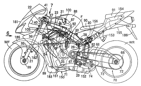
Referring to in Figs. I to 3, a body frame F of this motorcycle includes a
head
pipe 22 steerably supportiag a front fork 21 pivotally supporting a front
wheel WF.
7
CA 02461325 2004-03-16
Left-and-right pair of main frames 23 extend rearward and downward from the
head
pipe 22. A left-and-right pair of engine hangers 24 are welded to the head
pipe 22 and
front portions of the main frames 23 and extend downward from the main frames
23.
Connecting pipes 25 connect lower portions of both the engine hangers 2~ and
support
plate portions 33 provided on rest portions of the main frames 23,
respectively.
Left-and-right pivot plates 2~ extend downward from the rear portions of the
main
frames 23. A first crass pipe 27 is hung across the front portions of the
above-described main frames 23, a second cross pipe 28 is hung across upper
portions
of the above-described both pivot plates 26, and a third Cro55 pipe 29 is hung
across
lower portions of the above-described both pivot plates 2fi. A left-and-right
pair of
seat rails 30 extend rearward and upward and connect to the rear portions of
the
above-described main frames 23.
in Fig. fit, the head pipe 22 is one integrally including a cylinder portion
22a in
which the front fork 21 is steerahly supported. A left-and-right pair of
gussets 22b and
22b extend reazvvard and downward from the cylinder portion 22a. The main
flames
23 are formed of the gussets 22b, pipe members 31 of whack front end portions
are
welded to the gussets 22b, and pipe pordons 26a provided integrally with the
above-described pivot plates 26 and welded to rear end portions of the above-
described
pipe members 31.
In order to bang the first cross pipe 27 across the main frames 23 and 23,
attachment holes 32 are coaxially provided on inner walls of the main frames
23. Both
end portions of the first gross pipe 27 are inserted into these attachment
holes 32 and are
welded to the inner walls of the both main frames 23.
From both gussets Z2b and 22b of the head pipe 22, extended portions 22c and
22c extend rearward so as to be arranged inside of &oz~t inner walls of the
pipe members
31, and are formed integrally therewith so as to constitute front inner walls
of the main
frames 23. The end portions of the first cross pipe 27 are inserted into the
boles 32 so
8
CA 02461325 2004-03-16
as to oppose the bath ends to the front inner walls of the pipe members 31.
The both
end portions of the first cross pipe 27 are welded to outer surfaces of the
above-described both extended porfiions 22e of the first cross pipe 2.7.
Referring also to Fig. 5, each of the pipe members 31 is formed so as to have
an outer shape of a square cylinder, in a lateral cross section, by
conventionally known
extrusion or pultxusion molding for an ingot of an aluminum alloy. Between
intermediate portions in a vertical direction on inner side faces of each pipe
member 31,
a rib 34 vertically partitioning an inside of each pipe member 31 is provided
integrally
therewith. Note that, in a portion to which the engine hanger 24 is welded, a
lower
portion of each pipe member 3I is cut dowmvard, that is, so as to open toward
the
engine hanger 24 side.
Each pipe member 31 is formed into a vertically long square cylinder shape
having an inner wall 31a flat across substantially the whole length in the
vertical
direction and an outer wall 3 lb substantially along the inner wall 3 I a.
Each pipe
member 31 is bent in a plane PL orthogonal to the above-described inner wall
31a such
that an intermediate portion thereof in a loagitudinal direction is curved to
protrude out
sideward. xn addition, the bath pipe members 31 ai~er the bending are provided
continuously with the gussets 22b ofthe head pipe 22 in a tilted manner to
come closer
to each other in an upward direction.
In Fig. 6, the front fork 21 includes cushion units 35 extended vertically on
both Ieft and-right sides of the front wheel Wlr. A bottom bridge 3 6 connects
both
cushion units 35 above the front wheel WF, and a cop bridge 37 connect upper
portions
of the cushion units 35. A wheel axle 38 of the front wheel Wlc is pivotally
supported
between Iower end portions of the cushion units 35.
. With reference to Figs. 7 and 8 in addition, between the above-described
'bottom bridge 36 and top budge 37 on a rear side of a center portion between
the
above-described cushion units 35, a steering stem 39 parallel to the cushion
units 3S is
9
CA 02461325 2004-03-16
provided, This steering stern 39 is rotatably supported in the cylinder
portion 22a of
the head pipe 22.
To upper end portions of the above-described cushion units 3S above the
above-described bottom bridge 3b, left-and-right separate 'bar-shaped steering
handles
40 are connected. Moreover, bet~,veen a front end pozrion of the body frame F,
that is,
the head pipe 22, and the top bridge 37 in the front fork 21, a steering
damper 41 is
provided,
This steering damper 41 includes a housing 42 building an unillustrated
hydraulic damping mechanism therein and fixedly supported on the head pipe 22,
a
rotating shaft 43 arranged ecaaially above the above-described steering stem
39 and
rotatably supported in the above-described housing 42, an arm 44 extended
forward, a
base end portion of which is fixed to the rotating shaft 43, an elastic roller
45 pivotally
supported on a tip end ofthe arm 44, and a concave portion 46 provided on an
upper
surface of a center portion of the above-described top bridge 37 so that the
elastic roller
4S can be fitted into the same concave portion 46 in a manner that an outer
circumferential surface of the elastic roller 4S is brought; into frictional
contact
therewith.
By this arrangement, rotational vibrations around as axis of the steering stem
39, which are transmitted from the front vcvheel WF side to the top bridge 37,
will be
damped by the hydraulic damping mechanism in the housing 42 through the
above-described arxn 44.
Again in Fig. 2, an engine body St) of a mufti-cylinder engine E in which, for
example, four cylinders are arranged parallel to a width direction of the body
frame F is
supportEd oa the Iower portions of above-described both the engine hangers 24
and the
upper portions and lower poriioas of the above-described both pivot plates 26.
Then, to the lower portions of the engine hangers 24, the engine body 50 is
fastened by a left-and-ri,~t pair of bolts S 1.
CA 02461325 2004-03-16
In Fig. 9, to support the engine body 50 on the lower portions of the pair of
pivot plates 26 arranged on both sides of the engine body 60, in the lower
portion of one
of the both pivot plates 26 (in this embodiment, the pivot plate 26 arranged
on a right
side when facing forward in a traveling direction of the motorcycle), an
insertion hole
53 inserting a mount bolt 52 therethrough and a first engaging portion S4
surrounding
an outer end of the above-described insertion hole 53 are provided.
Specifically, in the
lower portion of the above-described one of piv of plates 26, the insertion
hole 53 open
to an inner side face of the pivot plate 26 and a first insertion hole 55
larger in diameter
than the insertion hole 53 and open to an outer side face of the pivot plate
26 are
provided coaxially As a circular step portion facing the first insertion hole
SS side, the
first engaging portion 54 is formed between the outer end of the insertion
hole $3 and an
inner end of the first insertion hole 55.
Moreover, in the engine body S0, a pair of support arm portions SOa arranged
between the above-described pivot plates 26 are integrally provided at an
interval in an
axial direction of the above-described mount bolt 52. fn these support arm
portions
SOa, through boles 56 inserting the mouth bait 52 theret:hrough are coaxially
provided.
In the lower portion of the other pivot plate 26, a screw hole 57 coaxial with
the above-descnbed insertion hole S3 and a second engaging portion 58
surrounding an
outer end of the screw hole 57 are provided. Specifically, in the lower
portion of the
other pivot plate 26, the screw hole 57 open to an inner side face of the
other pivot plate
26 and a second insertion hole 59 larger in diameter than the screw hole 57
and open to
an outer side face of the other pivot plate 26 are coaxially provided. As a
circular step
portion facing the second insertion hole 59 side, the second engaging portiota
58 i.s
formed between the outer end of the screw hole 57 and an inner end of the
second
insertion hole 59.
A cylindrical bolt 64 allowing one end thereof to abut on the engine body 50
is
screwed into the above-described screw hole 57. Specifically, the above-
described
lI
CA 02461325 2004-03-16
cylindrical bolt 60 is screwed to the screw hole 57 so as to allow the one end
to abut on
one of the support arm portions SOa in a state where the other support arm
portion SOa is
allowed to abut on the inner side face of one of the pivot plates 26. A
cylindrical
check bolt 61 abutting on the other end of the cyIindz~cal bolt 60 is screwed
to the sere«~
hole 57 to prevent the cylindrical bolt 60 from being loosened. In addition,
the
cylindrical bolt 60 and the check bolt 61 are screwed to the screw hole 57 in
a manner
that the other end of the cylindrical bolt 60 and the check bolt 61 are
located inwsrd of
the second engaging portion 58 in a state where the engine body 50 is
sandwiched
between the inner side face of the one of the pivot plates 26 and one end of
the
cylindrical bolt 60.
The above-described mount bolt 52 is one to be inserted through the insertion
hole 53, the both through holes 56 of the engine body 50, the cylindrical bolt
60, the
check bolt 61, and the above-described screw hole S7. A belt head poxtion S2a
on one
end of the mount bolt 52 is engaged with either one of the above-described
first and
second engaging portions S4 and S 8, and a nut 63 engaged with the other one
of the f zst
and second engaging portions S4 arid S8 is screwed to tlxe othez end portion
of the
mount bait 52. Then, in this embodiment, the other end portion of the mount
bolt 52,
in which the bolt head portion 52a is engaged with the first engaging portion
54, is one
protruding from the above-described screw hole 57. T'he nut 63 sczewed to the
other
end portion of the mount bolt SZ at the protruding poriipn from the screw hole
S7 is
engaged with the second engaging portion 58 while interposing a washer 62
therebetween,
A structure of supporting the engine body SO on the upper portions of the born
pivot plates 26 is basically the same as the above-described shucture of
supporting the
engine body SO on the lower portions of the pivot plates 26, and detailed
description
thereof will be omitted.
On intermediate portions in the vertical direction of the above-described both
12
CA 02461325 2004-03-16
pivot plates 26, a front end portion of a swing aim 66 is swingably supported
while
interposing a support shaft 67 trrerebetween. A wheel axle 68 of a rear wheel
VTR is
supported so as to be freely referable on zear end portions of this swing amt
66.
Power from an output shaft 69 of a transmission built in the above-described
engine body 50 is one to be transmitted to the rear wheel WR through chain
drive
transmission means 70. The chaia~ drive transmission means 70 is constituted
of a
drive sprocket 71 fixed to the above-described output shaft G9, a driven
sprocket 72
fixed to the rear wheel WR, and an endless chain 73 wound around these
sprockets 71
and,72, and is arranged on a left side of the engine E so that it faces
forward in the
direction the motorcycle is traveling.
Between the swing arm 66 and the third cross pipe 29 connecting the lower
portions of the both pivot plates Z6 and 26, a Link mechanism 74 is provided.
The link
mechanism 74 includes a first link 7S rotatable around an axis of a first
connecting shaft
77 parallel to the support shaft 67, in which one end portion is connected to
the
above-described third cross pipe 29, and a second Link 76 which is connected
to lower
portions of the swing arm 66 so as to be rotatable around an axis of a second
connecting
shah 80 parallel to the first canneeting shaft 77 and is connected to the
othez end portion
of the first link 73 while interposing therebetween a third connecting shaft
81 parallel to
the first and second connecting shafts ?7 and 80.
in the third cross pipe 29, a pair of bearing support portions 29a protruding
rearward at two spots spaced in a longitudinal direction of the third cress
pipe 29 are
integrally provided. The one end portion of the first link 75 is supported on
a collar 78
attached onto the fixst connecting shaft 77 provided between the bearing
support
portions 29a while interposing a pair of roller beatings 79 therebetween.
Moreover the other end portion of the first link 75 is connected to a rear
portion of the second link 7b while interposing the third connecting shaft 81
therebetween. A lower end poxtion of a rear cushion unit 82 of which upper
ei~d
I3
CA 02461325 2004-03-16
portion is connected to a bracket 66a provided in a front portion of the swing
arm 66 is
connected to a front portion of the second link 76 while interposing a fourth
connecting
shaft 83 therebefiween.
With reference to Fig. 10 in addition, above a cylinder head 86 in the engine
body 50, an air cleaner 87 for cleaning air to be supplied to the engine E is
arranged so
as to be located behind the head pipe 21 in the body frame F. A fuel tank 88
covering a
rear portion and upper por~.~ian of this air cleaner 87 is mounted on the main
frames 23 in
the body frame F, and a radiator 89 is arranged in front of the engine body
50. As
shown in Fig. Z, on the seat rails 30 behind the above-described fuel tank 88,
a main
seat 90 for seating a ridez eherean is supported, and a pillion seat 91 for
seating a rider
thereon is supported on the seat rails 30 at a position spaced rearr,~ard from
the main
seat 90.
To an upper sidewall of the cylinder head 86, intake passage portions 92,
extended straight so as to introduce the cleaned air from the air cleaner 87
above the
cylinder head 86, are connected for each of the cylinders_ Each of these
intake passage
portions 92 is one including a fusel 93 in which an open upper end portion
protrudes
into the aircleaner 87, and a throttle body 94 connects to a lower end of the
funnel 93.
The throttle body 94 is connected to the upper sidewall of the cylinder head
86 white
interposing an insulator 95 therebetween.
Meanwhile, the air cleaner 87 is one formed by ;C~:edly housing a cylindrical
cleaner element 97 in a cleaner case 96. Around the cleaner element 97 in tfe
cleaner
case 96, a cleaner chamber 98 into which the air is cleaned by passing through
the
cleaner element 97 is fornaed. The funnels 93 at upstream ends of the
respective intake
passage portions 92 are attached in line onto the cleaner case 96 so as to
open to the
cleaner chamber 98,
First injectors 100 for injecting fuel when the engine E rotates at High speed
are
attached onto the cleaner Case 96 in the air cleaner 87 for each of the
cylinders of the
14
CA 02461325 2004-03-16
engine E. The first injectors I00 are arranged in front of centerline C1 of
the
respective intake passage pord.ons g2, and are attached onto the cleaner case
9G so as to
have an axis tilted with respect to the centerline Cl . Tn addition, an
unillusuated fuel
pump is built in the fuel tank 88, and the fuel is supplied from the fuel pump
to the first
injectors I00_
Moreover, a fuel filler 101 is provided on a front portion of the fuel tank
88.
The first injectors 100 are arranged in front of a centerline C2 of the fuel
filler 10I.
On a projection diagram onto a plane parallel to the centerline C2 of the fuel
filler 101
and the centerlines C1 ofthe intake passage portions 9Z, the first injectors
100 are
attached onto the cleaner case 96 such that upper portions thereof are
arranged in front
of intersection P of the centerlines C I and C2.
In,the throttle bodies 94 in the respective intake passage portions 92,
throttle
valves (not shown] for controlling amounts of intake flowing through the
intake passage
portiofls 92 are built. Throttle drums I02 connected to the throttle valves
are arranged
on sides of the throttle bodies 94.
In addition, on the engine E side than the above-described throttle valves and
an rear sides of the throttle bodies 94, second injectors 103 receiving a
supply of the
fuel from the fuel pump in the fuel tank 88 and injecting the fuel in a drive
state of the
engine E are attached The second injectors I03 are on a side opposite to the
engine E,
and are tilted to a side of centerline Cl that is the opposite of the first
injectors 100.
Referring to Figs. Z 1 to I4, below the head pipe ?2 provided on the front end
of
the body frame F, an intake duct I05 for introducing external air into the air
cleaner 87
is aaanged so as to be extended forward from the air cleaner 87. A rear end
portion of
the intake duct 105 is protntded into a lower portion of'the cleaner case 9b
and fixed
thereto so as to introduce the external air into the cleaner element 97 in the
above-described air cleaner 87.
This intake duct 105 is consfituted of a rear duct main body 106 having an
15
CA 02461325 2004-03-16
approximately triangular lateral cross-sectional shape in wr~ich a center
portion in a
width direction raises upward and a lower portion is open. A front duct main
body 10?
has substantially the same lateral cross-sectional shape as that of the rear
duet main
body 106 and is joined to a front portion of the tear duct main body I06, and
Iower
cover plate 108 closing Iower opening ends of the front and rear duct main
bodies I06
and 10'7. The intake duct 105 is formed such that a rear portion thereof is
tilted
rearward arid upward when viewed from a side thereof. Then, the lower cover
plate
108 is fastened to the rear duct main body 106 by a plurality of screw
rnernbers 10~, and
fastened to the front duct main body 10? by a plurality of screw members 110.
To lower front surfaces of the pipe members 31 partially constituting the main
frames 23 in the body frame F, support stays 111 are fixed by screw members
112.
Attaahr~aent bosses 1 I 3 provided on both sides of a lower front portion of
the intake duct
105 axe fastened to the above-described suppozt stays 111 by screw members
114, and
thus a front portion of the intake duct l OS is supported on the body frame R
1n
addition, positioning pins 113a inserted through the support stays 111 are
prom~ded
from the above-descn'bed attachment bosses 1 i3.
Moreover, the radiator 89 is arranged below the intake duct I05, and from both
sides of this radiator 89, stays 115 are extended upward. Meanwhile, onfio the
above-described support stays I l I, weld nuts 116 are fixedly attached. The
bolts 1 I7
inserted through the stays l I5 and the support stays 111 are screwed and
tightened to
the above-desen.'bed weld nuts 1 I6, and thus the radiator 89 is supported ozr
the body
frame F
On the lower cover plate 108 in the intake duct I OS, a pair of partition
walls
I 18 abutting on lower surfaces of upper portions of the fx°ont and
teat duct main bodies
l Od and 10? are provided integrally therewith. In the intake duct 105, formed
are a
first intake passage I 19 of which center portion in a width direction is
arranged on a
centerline C3 in a width direction of the front wheel WF, and a left-and-right
pair of
I6
CA 02461325 2004-03-16
second intake passages I20 arranged on both sides of the first intake passage
1 I9, such
that the first intake passage 119 snd the second intake passages 1Z0 are
partitioned by
the partition walls 118. A ilow area of the first intake passage 119 is set
larger than a
total flow area of the pair of second intake passages 120.
In addition, fTOnt portions of tha partition walls 118 are formed into a shape
tilted so as to be separated from each other as going forward. Front end
portions of the
partition walls 118 abut on inner surfaces of both sidewalls of the front duct
main body
107, and afront portion of the first intake passage 119 is open forward at a
front end of
the intake duct 105 so as to occupy the whole of a front end opening portion
(air intake)
of the intake duct 1 OS, AZoreover, front end opening portions (air intake)
120a of the
second intake passages 120 are ones to be fozmed on a front end portion of the
intake
duct 105 so as to open to a direction different from an opening direction of
tlae front end
of the first intake passage 119. In this embodiment, the front end opening
portions
120a are formed on the front duct main body I07 so as to open upward on both
left-and-right sides of the front end portion of the first intake passage 119.
When viewed from front, the front end portion of the intake duct l OS is one
to
be formed into the approximately triangular shape such that an upper edge
thereof is
made to ga along a lower end edge of a continuous por4or~ of the head pipe 21
and both
main fumes 23 and 23 and that a lower edge portion thereof is made to go along
an
upper portion of the radiator 89. A gziil 121 is attached onto the from end
portion of
the intake duct 105.
This grill I2I is ozre formed by supporrtng a circura~ferential edge portion
of a
mesh member 123 on a frame member 122 of a shape corresponding to a front end
opening edge of the intake duct 105. 4n the frame member I22, bale boards 122a
are integrally provided and arranged at positions spaced from the above-
descx~~bed froni
end opening portions d ZOa while forming gaps from the front end opening
portions 120a,
These ba:~le boards 122a are fastened to both front sides of the front duct
main body
17
CA 02461325 2004-03-16
107 in the intake duct 105 by screw members 124. Moreover, from a front end of
the
above-descn'bed lower cover plate 108, positioning pins 125 for inhibiting a
lower
portion of the frame member 122 from leaving from the front en.d portion of
the intake
duct 10~ are protruded so as to be inserted through the lower portion of the
frame
member 122.
Tn the first intake passage 119, arranged is a butterfly-shaped first intake
control valve 126 contt~olled to open and close in response to the numbez of
revolutions
of the engine E so as to close the front end opening portion I 19c of the
first intake
passage 119 when the engine E rotates at Iow speed and so as to open the front
end
opening portion 119c of the first intake passage 1 I9 when the engine E
rotates at high
speed (6000 x p.m. or more). Moreover, in the second intake passages 120,
arranged
are butterfly shaped second intake control valves 127 conuolted to open and
close in
response to the number of revolutions of the engine E so as to open the front
end
opening portion IZOa the second intake passages 120 when the engine E rotates
at low
speed and so as to close the front end opening portion 120a the Second intake
passages
I20 when the engine E rotates at high speed.
Fig. 20 shouts a pattern where the first control valve I26 is opened and
closed
in response to the number of engine revolutions. In this drawing, a full close
position
of the f rst intake control valve I 26 means a position shown by a solid line
in Fig. 14,
aad a fuh open positron thereof means a position shown by a dotted line in
Fig. 14.
Note that the first intake control valve I26 raay be opened and closed in
response to
vehicle speed instead of the number of engine revolutions. For example, the
first
intake control valve 126 could be opened when the motorcycle teaches a fixed
speed.
Then, the first intake control valve I26 and the second intake control valves
127 commonly include a valve shaft 128 having its axis ozthogonal to the
#lowing
direction of the air Mowing through the first ,intake passage Z 19 and
rotatably supported
in the intake duct 105, and is cansrituted as a valve unit (member opening and
closing
18
CA 02461325 2004-03-16
the air intake) V'11 that is a single structure, As shown in :Fig. 12 the
first intake control
valve 126 and the second intake control valves 127 are attached in the same
direction.
Hence, when the front end opening portion 119a of the first intake passage I19
is opened by the first intake control valve 126, the front end opening
porfiions 120a of
the second intake passages 124 will be closed by the second intake control
valves I21.
Moreover, when the front end opening portion 119a is closed by the first
intake control
valve 126, the front end opening porcians 120a of the second intake passages
120 will
be opened by the second intake control valves 1,27. .
The valve shaft 128 is one rotatably supported by the partition walls 118 at
portions corresponding to the front end opening portions 120a of the second
intake
passages 120 in the intake duct 10~. Among the plurality of screw members 110
fastening the front duct main body 107 to the lower covet plate 108, two pairs
of the
screw members 110 are screwed into the partition walls 118 at positions where
the
screw members 110 sandwich the valve shaft I28 from both sides.
The first intake control valve 126, which changes the flow area of the first
intake passage 119, is fixed to the valve shaft 128 in a manner of having a
posture tilted
rearward and upward is a state of closing the first intake passage 1 lg as
shown in Fig.
14. In addition, the first intake control valve 126 is formed such that, in a
valve
closing state thereof, an area of a portion above the above-described valve
shaft 128 is
set larger than an area of a portion below the above-described. valve shaft
128,
Moreover, the first intake control valve I26 is set substantially horizontal
in a valve
opening state thereof as shown by a dotted line of Fig. 1~ such that
resistance to the air
flowing thzough the first intake passage 119 becomes minimum.
'fhe second intake control valves I27 changing the flow areas of the second
intake passages I20 are fixed to the valve shaft 128 so as to open the front
end opening
portions I20a of the second intake passages 120 in the state where the first
intake
control valve 126 closes the first intake passage l I9.
19
CA 02461325 2004-03-16
Hence, as shown in Fig. 21 (a), when the engine E rotates at the high speed,
the
valve unit VtJ opens the first intake control valve 126 and closes the second
intake
control valves 127, thus introducing the external air therethrough from the
front end
opening portion 119a of the first intake passage 119. Meanwhile, as shown in
Fig.
21 (b), when the engine E rotates at the low speed, the valve unit'VTI closes
the first
intake control valve 126 and opens the second intake control valves I2T, thus
introducing the externsl air therethrough from the front end opening poriion5
120a of
the second intake passages 120.
Behind the shaft 12S and below the intake duct 1.05, a rotation shaft I30
parallel to the valve shaft 128 is arranged. This rotation shah 130 is
rotatably
supported by a plurality of bearing portions 129 protruded from a lower
surface of the
intake duct 105, that is, a lower surface of the lower cover plate 108.
An arm 130a is provided to the rotation shaft 130 at a portion corresponding
to
the first intake passage 119. The arm 130a is connected to one end of a
evnnecring rod
131 penetrating the lower portion of the intake duct 105, that is, the tower
cover plate
108, the other end of the connecting rod 131 being connected to a portion
above the
valve shaft 12$ in the first intake eor~fiol valve 126 in the valve closing
state. Hence,
the first intake control valve 126 will be rotationally driven between the
valve closing
posirion shown by a solid Iine of Fig. I4 and the valve opening position shown
by the
dotted line of Fig. 14 in response to rotation of the rotation shaft 130.
In addition, between both end portions ofthe rotation shaft 130 and the intake
duct 105, return springs 132 are provided for exerting spring forces
rotationally
energizing the rotation shaft 130 and the valve shaft 128 to a direction where
the first
intake controi valve 12t is brought to the valve closing position. Moreover,
the
connecting rod 131 movably penetrates a through hole 133 provided in the lower
cover
plate 108. This through hole 133 is formed to be long in a fore-arid-aft
direction so as
to correspond to a position where the connecting rnd 131 penetrates the lower
cover
CA 02461325 2004-03-16
plate 108 in the fore-and-afl direction in response to a rotational motion of
the arm 130a
together with that of the rotation shaft 130.
A driven pulley 134 is fi~:ed to one end of the abo~re-described rotation
shaft
I30. To this driven pulley 134, rotational force is transmitted throw a first
transmission wire 135 from an actuator 141 which is supported by one of
support plate
portions 33 provided on the rear portions of the main frames 23, and is
arranged on an
upper lefr side of the engine body 50.
In Fig. 1S, the actuator 141 is one formed of az~ electric motor capable of
rotating forward and reverse, and a reduction mechanism transmitting power of
the
elecrric motor at reduced speed. The actuator 141 is attached onto a pair of
brackets
33a provided on one of support plate portions 33 in the body frame F by a bolt
143
while interposing elastic rr~embers 142 therebet~een. ~ln a drive pulley 14S
fixedly
attached onto an output shaft 144 which this actuator 141 includes, a small-
diarereter
first wire ~xoove 146 and large-diameter second and third wire grooves 147 and
148 are
provided.
An end portion of the first transmission wire I35 for transmitting the
rotational
force to the driven pulley I34 on the intake duct 105 side is engaged with the
rirst vVire
groove 146 so as to be wound therearound.
An electronic control unit I49 is connected to the actuator 141. The
electronic control unit I41 controls an operation of the actuator 149 in
response to the
number ofrevolutions ofthe engine, which is inputted from an unillusbrated
sensor.
Another actuator 141' is shovm in Fig. The above-described electronic control
unit 149 is connected to the actuator 14I', and the electronic control unit
149 controls
the operation of the actuator 141' in response to the number of engine
revolutions,
which is inputted fmm an unillustrated sensor. Here, the other constitutions
of the
above-described actuator 141' are similar to those of the above-mentioned
actuator 141,
and aecorditigly, reference xiumerals added with "' (apostrophe)" for the same
portions
21
CA 02461325 2004-03-16
are added thereto, and description thereof vszll be omitted. ATOte that, in
1~igs. 1 and 2,
only the actuator 141 is shown, and illustration of the actuator 14I' is
omitted. l3ere,
in the case of opening and closing the above-described valve unit VLT in
response to the
number of engine revolutions E, the number of revolutions of the engine fi is
used as a
common input signal, and accordingly, both of the valve unit ~TCT and the
exhaust
control valve 156 can be driven by either one of the above-described actuator
141 and
actuator I41'.
Aitemateiy, the actuator I41 can be driven in response to a signal from a
vehicle speed sensor.
Again in Figs. 1 and 2, an exhaust system 150 continuous with the engine E
includes individual exhaust pipes I S I individually connected to front
sidewall lower
portions of the cylinder head 86 in the cylinder body 50, a pair of first
collecting
exhaust pipes 152, each of which commonly connects a pair of the individual
exhaust
pipes I51, a single second collecting eshaust pipe 153, to which the pair of
first
collecring exhaust pipes I S2 are commonly connected, and which has a first
exhaust
muffler I54 interposed in art intermediate portion thereof, and a second
exhaust mufrler
155 connected to s downstream end of the second collecting exhaust pipe 153.
Each of the individual exhaust pipes 151, is arranged so as to extend downward
from the front of the eng'me body 50, and the first collecting exhaust pipes
152 are
arranged below the engine body 50 so as to extend substantially in the fore-
and-aft
direction. Moreover, the second collecting exhaust pipe i 53 is erected
between the
rear wheel WR and the engine body 50 while being curved so as to go from below
the
engine body 50 toward the right side of the vehicle body; and is further
extended
rsatwsrd above the rear wheel WR. Then, the ~trst exhaust muffler 154 is
interposed
in the erected portion of the second collecting exhaust pipe 153, and a rear
end exhaust
portion of the exhaust system 150, that is, the downstream end portion of the
second
exhaust mu~Ier I55 is arranged at a position above the wheel axle 68 of the
rear wheel
22
CA 02461325 2004-03-16
Refezring to Figs. 1 G and 17, in the second collecting exhaust pipe 153
consixtuting a part of the exhaust system 130, at a portion located in front
of and above
the wheel axle 68 of the above-described rear wheel VCR, a wide portion 153a
is
provided. In this wide portion lS3a, an ea;haust control valve 1 S6 is
provided as an
operating member for controlling exhaust pulses in the exhaust system 150 by
changing
a flow area in the second collecting exhaust pipe 1S3 in response to the
number of
revolutions of the engine E.
The exhaust control valve l S6 operates to a closing side in Iow/middle-speed
rotation ranges of the engine E in order to achieve power enhancement of the
engine E
by use of an exhaust pulse effect in the ekhaust system 150, and operates to
an opening
side in a high-speed rotation range of the engine E in order to achieve the
power
enhancement of the engine E by reducing exhaust flow resistance in the exhaust
system
1 S0. The exhaust control valve 156 is fia-ed to a valve shaft 157 rotaiably
supported in
the wide portion 153a of the second collecting exhaust pipe 1 S3.
One end of the valve shaft 157 is supported on a bottom having cylindrical
bearing housing 158 f'exedly attached onto the diameter-expanded portion 153a
while
interposing a seal merrrzber 159 tlaerebetween. Onto th.e other end portion of
the valve
shaft 1 ~7, which protzudes from the diameter-expanded portion 153a while
interposing
a seal member 160 between the same other end portion and the wide portion
153x, a
driven pulley 161 is fixed.. Between the valve shaft 1.57 and the wide portion
153a, a
return spring 162 is provided to energize the above-described valve shaft 157
to the side
of the opening of the exhaust control valve 156.
The protruding portion of the valve shaft 157 fsom the above-described wide
portion 153x, the driven pulley 161 aad tlz.e return spzing 162 are housed in
a case I65
formed of a cup-shaped case body 163 fixed to the wide (diameter-expanded)
portion
I53a, and a cover plate I 64 fastened to the case body I 63 so as to close an
open end of
23
CA 02461325 2004-03-16
the case body I63.
In addition, in the case 165, a regulator arm 166 ofwhich tip end portion
protrudes from an outer circumference of the driven pulley 161 is fzxed to the
valve
shaft 157. On an inner surface of the case body I63 in t"ite case 165, there
is provided
a closing-side stopper 167 making the tip end portion of the regulator arm I66
abut
thereon, thus regulating a rotating end of the valve shaft 157 (that is, of
the exhaust
control valve 156 to the closing side). There is also an opening-side stopper
168
making the tip end portion of the regulator arm 1 &G abut thereon, thus
regulating the
rotating end of the valve shaft 157 (that is, of the exhaust control valve 156
to the
opening side).
One end portion of a second transmission wire 171 operating the
above-described exhaust control valve 156 to the closing side when being
pulled is
engaged with the driven pulley 161 so as to be wound therearound. One end
portion of
a third transmission wire 1.72 operating the above-described exhaust control
valve 1S6
to the opening side when being pulled is engaged with the driven pulley 161 so
as to be
wound therearound. As shown in Fig. 15, the other end portion of the second
transmission wire 171 is engaged with the second wire groove 147 of the drive
pulley
144 in the actuator 141 so as to be wound tlterearound from a direction
reverse to a
winding direction of the first transmission wire 135. As shown in Fig. I5, the
other
end portion of the third transmission wire 172 is engaged with the third wire
groave I48
of the drive pulley 144 sa as to be wound therearound from the same direction
as the
winding direction of the first transmission wire 135.
Specifically, the actuator 141 for driving the exhaust control valve 156
controlled in response to the number of revolutions of the engine E will be
connected to
the first intake control valve 126 in the intake duct 105 in order to
rotationally drive the
first intake control valve 126.
In the second collecting exhaust pipe 153, it is desirable that the wide
portion
24
CA 02461325 2004-03-16
1 S3a, in which the exhaust control valve 156 is 'provided, be arranged below
the main
seat 90 in order to avoid undesired external force from the above operating
onto the
second and third transmission wires 171 and 172 as much as possible. Moreover,
the
case 165 is arranged so as to be exposed to the outside when viewed fxom a
side in order
to be facilitated to be blown by a running wind.
It is desirable that the above-described actuator 141 be arranged behind and
above the engine body 50 at a position where a distance between the actuator
141 and
the valve shaft 128 in the intake duct I05 and a distance between the actuator
141 and
the valve shaft 157 of the exhaust control valve 1S6 become substantially
equal to each
odzer. In such a way, obstructions interposed between the driven pulley 161 of
the
exhaust control valve 1 S6 and the actuatoz I4I are zeduced, and cabling of
the second
and third transmission wires 171 and 172 connecting the above-described pulley
I6I
and actuator 141 can be facilitated.
Tn Figs. 18 and i 9, in the first collecting exhaust pipes 152 constituting a
part
of the exhaust system i S0, wide portions 152a are provided at 'positions
located below
the engine body S0. Catalyst bodies 175 are housed in these wide (diameter-
expanded)
portions lS2a. VVhen the catalyst 'bodies 175 are arranged below the engine
body SO as
described above, it is possible that exhaust gas discharged from the cylinder
head 86
flows through the catalyst bodies 17S while being kept at relatZvely high
temperature.
Each of the caxalyst bodies 175 is formed in a manner that a catalyst carrier
17~
allowing the flow of the exhaust gas through a cylindrical case 176 and fozmed
in a
circular column shape is housed in the case 176 while arranging one end
thereof inward
of one end of the case 176, The case 176 is formed of a material different
from that of
rha first colteotitlg exhaust pipes I52. For example, while each first
collecting exhaust
pipe 152 is made of titanium, each case 176 and catalyst carrier I77 of the
ca~Lalyst body
175 is made of stainless steel.
To an inner circuxnferential surface of the wide (diameiet-expanded) portion
25
CA 02461325 2004-03-16
1 S2s in the first collecting exhaust pipe 152, a bracket 178 made of the same
material as
that of the first collecting exhaust pipe 152, for example, titanium, is
welded. This
bracket 178 integrally has a large ring portion I78a surrounding the one end
portion of
the case I76 and fitted into the diameter-expanded portion 152x, a small ring
portion
178b continuous with the large ring portion 178a in a manner of fitting the
one end of
the case 17G thereinto, and extended arm portions 178c, extended from a
plurality of
spats of the small ring portion 178b, for example, for spots at an equal
inner>al in a
circumferential direction to a side opposite to the large ring portion 178x.
Through holes 179 are provided on a plurality of spots in the circmnferential
direction of the wide tdiameter-expanded) portion 1 S2a so as to be made to
face an
outer circumferential surface of the large ring portion 17$x. The large ring
portion
178a is welded to the wide portion 152a through these through holes 179, and
thus the
bracket 1?8 is welded to the wide portion I 52a of the first collecting
exhaust pipe 152.
Moreover, the respective extended arm portions 178c, are ones to be crimped to
the one
end of the case 176 in the catalyst carrier 175. The bracket 178 welded to the
wide
portion 1 S2a of the first collecting exhaust pipe 152 will be czimped to the
one end of
the case 17d at portions protruding from one end of the catalyst carriez 177.
Moreover, onm an outer surface at the other end of the case 176 in the
catalyst
body 175, a ring 184 formed of stainless mesh is fixedly attached by spot
welding.
'This ring 180 is interposed between the wide portion 152a of the first
collecting exhaust
pipe 152 and the other end portion of the case 176. Thus, it is made possible
that the
other end side of the catalyst carrier 175 in which the one end side is fixed
to the wide
portion I52a while interposing the bzacket 178 therebetween slides due to
thermal
expansion. A stress due to the thermal expansion of the catalyst carrier 175
can be
avoided between the one end portion of the catalyst body 175 and the wide
portion
152x.
With another reference to Fig. 1, front of the head pipe 22 is covered with a
26
CA 02461325 2004-03-16
front cowl i81 made of synthetic resin. Both front sides of the vetaicle body
are
covered with center cowls 182 msde of the s5rnthetic resin, which are
continuous with
the front cowl 181. A lower cowl 183 made of the syntlxetic resin, which
covers the
engine body SO from both sides is provided continuously with the center cowls
182.
Moreover, rear portions of the seat rails 30 are covered with a rear cowl I
84.
A front fender 18S covering the above of the front wheel WF is attached onto
the front fork 21, and a rear fender 186 covering the above of the rear wheel
'WR is
attached onto the seat rails 30,
Next, the operation of one embodiment of the present invention will be
described. The first cross pipe 27 is hung across the front poTlions of the
lefr-and-right
pair of main frames 23 provided continuously with the head pipe 22 at the
front end in
the body frame h. The attachment holes 32 are coaxially provided on the fxont
inner
walls of the main frames 23. The both end portions of the first cross pipe 27
inserted
into these attachment holes 32 are welded to the inner walls of the both main
frames 23.
Hence, insertion amounts of the both end portions of the first cross pipe 27
into the
attachment holes 32 are changed, and thus a dimensional error between the
left-and-right pair of main frames 23 and a length error in ati axial
direction of the first
cross pipe 27 are absorbed, and the end portions of the fist crass pipe 27 can
be
securely welded to the inner vcraIls of the main frames Z3 and 23,
Moreover, the head pipe 22 is one integrally including the cylinder portion
22a
steerably supporting the front fork 21, and the left-and-right pair of
,gussets 22b and 22b
e.Ytended rearward and downward from the cylinder portion 22a. The main frames
23
are ones including at least the gussets 22b, and the pipe members 31
individually
welded to these gussets 22b. To the gussets 22b, the extended portions 22c
extended
rearward so as to be arranged inward than the front inner walls of the pipe
members 31
are provided integrally therewith so as to constitute the front inner walls of
the main
frames 23. In addition, in the both extended porlians 22c, the attachment
holes 32
27
CA 02461325 2004-03-16
inserting the end portions of the first cross pipe 27 therethrough so as to
oppose the ends
to the front inner walls of the pipe members 31 are provided, and the end
portions of the
first cross pipe 27 are welded to the outer surfaces of the extended portions
22c of the
first cross pipe 27. Specifically, the end portions of the first crass pipe 27
are welded
to the outer surfaces of the extended portions 22c integral with the gussets
22b partially
constituting the both main frames 23. Accordingly, welding the first cross
pipe 27 to
the main frames 23 is facilitated, and in addition, an e~aerior appearance can
be
improved because the welded portions are not visible from the outside.
Moreover, each pipe member 3I is formed into the vertically long square
cylinder shape having the inner wall 3Ia flat across substantially the whole
length in the
vertical direction and the oezter wall 31b substantially along the inner wall
31a, and is
bent in the plane PL orthogonal to the inner wall 31a. Accordingly, it is easy
to bend
the pipe members 31.
In addition, the both pipe members 31 are provided concinuvusly with the
gussets 22b of the head pipe 22 in a tilted manner to the side of coming
closer to each
other in an upward direction, Accardingly, with a simple smzcture of just
tilting the
pipe members 31, a space between the lower portions of the both pipe members
31 is
widened, and thus a space for arranging the engine E can be sufficiently
ensured,
Moreover, a distance between the upper portions of the both pipe members 31 is
narrowed, and thus it is less h'lve'ly that the knees of a rider will coatact
pipe members
31.
In case of supporting the engine body 50 on the upper and lower portions of
the
pivot plates 26 in the body frame F; in one of the pivat plates 26, there are
provided the
iaseriian hole 53 inserting the mount bolt 52 therethrough, and the first
engaging
portion 54 surrounding the outer end of the insertion hole 53 so as to engage
therewith
the bolt head portion 52a on the one end of the mount bolt 52. Iz~ the other
pivot plate
26, the screw hole 57 coaxial with the insertion hale 53, and the second
engaging
28
CA 02461325 2004-03-16
portion 58 surrounding the outer end of the screw hole 57 aze provided. The
cylindrical bolt 60 is screwed to the screw hole 57 so as to sandwich the
engine body 50
betv~~eea the one end thereof and the inner side face of one of the pivot
plates 26 and to
locate the other end inward of the second engaging portion 58. The not 63
capable of
being engaged ,with the second engaging portion 58 is screwed to the othex end
portion
of the mount bolt 52 inserted through the insertion hole S3, the engine body
50, the
cylindrical bolt GO and the screw hole 57 and protruding from the screw hole
57.
With such a support structure of the engine body SO on the body frame F, a
screwing posil7on of the cylindrical bolt 60 to the sezew hole S7 is adjusted,
and thus the
engine body 50 can be securely sandwiched between the one of the pivot plates
26 and
the one end of the cylindrical bolt 60 while absorbing a dimensional error
between the
both pivot plates 26 and a dimensional error in the width direction of the
engine body 50.
In addition; the bolt head portion ~2a on the one end of the mount bolt 52 is
engaged
with the first engaging portion 54 of the one of the pivot plates 26, and the
nut 63
screwed to the other end portion of the mount bolt 52 is engaged with the
second
engaging portion S8 of the other pivot plate 26. Accordingly, the both ends of
the
mount bolt 52 can be fastened to the body frame F such. that a position
thereof in the
axial direction is accurately determined, and support rigidity for the engine
body 50 can
be enbanced.
l~2oreover, the cylindrical check bolt 61 abutting on ttae other end of the
cylindrical bolt 50 is screwed to the screw hole 57 so as to be located inward
of the
second engaging portion 58. Accordingly, the check bolt 61 is brought into
contact
with the other end surface of the cylindrical bolt 60, and thus the
cylindrical bolt 60 can
be effectively prevented from being loosened_
?o the upper sidewall of the cylinder head 86 which the engine body SO
includes, the intake passage portions 92 extended straight so as to introduce
the cleaned
air fmm the air cleaner 87 atxanged above the cylinder head 86 ate connected.
The
29
CA 02461325 2004-03-16
first injectors 100, which inject fuel into the intake passage portions 92
from above the
same, are attached onto the cleaner case 96 of the air cleaner 8'7. The fuel
tank 88 is
arranged so as to cover the rear portion and upper portion of the air cleaner
87. The
first injectors I00 are arranged in front of the centerline C1 of the intake
passage
portions 92.
Specifically, the first injectors 100 will be arranged at the positions offset
to
front from the centerline C1 of the 'intake passage portions 92. On the
centerline C1 of
the intake passage portions 92, it is possible to set a bottom wall of the
fuel tank 8g on a
relatively low position while avoiding interference with the first injectors
100. Hence,
the volume of the fuel tank 8$ can be increased or st least easily accounted
for.
Moreover, the first injectors 100 are arranged in front of the centerline C2
of
the fuel filler I OI provided on the front portion of the fuel tank 88, and,
therefore, the
first injectors s 00 do not interfere with the fuel tank 88. Accordingly, the
fuel filler
I O 1 can be set at a lower position. In addition to this, on the projection
diagram onto
the plane parallel to the centerline C2 of the fuel filler 101 and the
centerlines C1 of the
ixltake passage portions 92, the first injectors 100 are attached onto the
cleaner case 96
of the air cleaner 87 such that the upper portions thereafare arranged in
front of the
intersections P of the centerlines C1 and C2. Accordingly, it is possible to
set the
bottom wall of the fuel tank 88 on the lower position in front of the
centerline C2 of the
fuel filler I OI, and it !5 alSO possible to mote easily ensr~re the volumes
of the fuel tank
88 and air cleaner 87 are adequate. IrA addition, it also makes the insertion
of a fuel
service nozzle into the fuel tank at the time of fueling easier
Furthermore, onto the rear sides of the throttle bodies 94 in the intake
passage
portions 92, the second injectors 103 injecting the fuel into the intake
passage portions
92 are attached, Accordingly, the first injectors 100 iajectir~,g the fuel
from above the
intake passage portions 92 in order to contribute to the power enhancement of
the
engine E so as w be supplied with fuel of relatively low temperature, and the
second
CA 02461325 2004-03-16
injectors 103 capable of injecting the fuel in good response to the drive of
the engine E,
can be arranged by effectively using with goad balance the space far arranging
the
intake passage portions 92.
The intake duct 105 extended forward from the air cleaner 87 arranged on the
head pipe 22 on the front end of the body frame F is arranged below the head
pipe 22.
In this intake duct 105, formed are the fzrst intake passage 119 of which
center portion
in the width diction is arranged on the centerline C3 in the width direction
of the front
wheel ~sJF, and the left-and-right pair of second intake passages 120 arranged
on the
both sides of the first intake passage 119, such that the flow area of the
first intake
passage 119 is set largez than the total flow axes of the pair of second
intake passages
120_ Tlta first intake control valve 126 closing the first intake passage 119
when the
engine E rotates at Iow speed is arranged in the first intake passage 119 so
as to open the
front er~d position 119a of the $rst intake passage 119 wizen the engine E
rotates at high
speed.
With such a eonstatution of the intake duct 103, wizen the engine E operates
at
low speed, that is, when running the motorcycle at Iow speed on a road with,
for
example, standing water or other foreign objects that may be splashed or
ricocheted
towards the intake duct log, the first intake passage 119 of which center
portion in the
width direction is arranged on the centerline C3 in the v~ridth direction of
the front wheel
WF is closed. Accordizrgly, the water or foreign objects can be largely
prevented from
entering the air cleaner 87. Moreover, when the engine E rotates at high
speed, it is
difficult for the water to be splashed upward or the foreign objects to be
ricocheted
upward due to the wind moving from the front of the vehicle. Accordingly, the
water
or foreign objects can be largely prevented from entering the air eieanec 87.
Furthermore, at higher speeds, the first intake passage 119 of which flow area
is large
opens to introduce the air of a relatively large volume into the air cleaner
87, thus
making it possible to contn'bute to the power enhancement of the engine.
31
CA 02461325 2004-03-16
Moreover, when the vehicle runs at low speed as described above, that is, when
the engine E xotates at low speed, the first intake control valve 126 is
closed, thus
making it possible to reduce a suction noise. Note that, when the first intake
passage
119 is opened as described above, the second intake passages I20 and 120 are
closed,
and accordingly, the water and foreign objects can be prevented from entering
these
portions,
I-Iere, the ram air ei~'ect is one, in which the intal~e air is positively
supplied to
combustion chambers so as to be forced thereinto by wind pressure, and thus an
amount
of the intake air is increased and charging efficiency is increased to obtain
ideal intake
performance, thus making it possible to achieve a power enhancement of the
engine E.
Moreover, to the valve sha$128 rotatably supported in the intake duct 105,
fixed are the first intake control valve 126 and the pair of second intake
control valves
127 individually changing the flow areas of the second intake passages 120 so
as to
individually open the front end positions 120a of the second intake passages
I20 when
the engine E rotates at low speed and so as to individually close the front
end portions
120a of the second intake passages 120 when the engine E rotates at high
speed.
The fsrst intake control valve 126 and the second control valves 127 are
controlled to open and close as described above. 'Thus, an intake amount is
restricted
to be small when the engine E operates at low speed, and thus it is possible
to obtain
good acceleration perforn~ance by supplying an appropriately rich mixture to
the engine
E while restricting the mi~;ture fronn being lean at the time of an
acceleration operation.
Moreover, volume eff'tozency of the engine E is enhanced by reducing intake
resistance
when the engine lr operates at high speed, thus making it possible to
contribute to a
higher power performance. In addition, the first intake control valve 126 arid
the pair
of second intake control valves 127 can be driven to open and close by
rotationally
driving the valve shaft 128, and accordingly, the structure is made simple,
which can
result is cost and weight reduction.
32
CA 02461325 2004-03-16
Furthermore, the front end opening portion 119a of the first intake passage
119
is provided on the center portion in the vehicle width direction, and the
front end
opening portions I20a of the second intake passages 120 are provided in a
manner of
being distributed on the both sides thereof, Accordingly, a balance in
introducing the
intake can be ensured between the left and right sides, and the arrangement
and
constitution of the air intake passages is simplified.
Moreover, the baffle boards 122a arranged at the positions spaced from the
front end opening portions 120a while fornning the gaps from the front end
opening
portions 120a are attached inio the intake duct 105. When the external air is
introduced from the second intake passages I20 into the air cleaner 87, the
water and
the foreign object can be avoided entering the second intake passages 120 as
much as
possible due to a labyrinth structure by the bafr~e boards l2Za.
In addition, the front end of the first intake passage 119 is rcaade open to
front at
the front end of the intake duct IOS, and the front er~d opening portions 120a
of the
second intake passages 120 are forxcied on the front end portion of the intake
duct 105 so
as to open to the direction different from the opening direction of the front
end of the
first intake passage I 19. Accordingly, when the engine E rotates at high
speed, wind is
introduced into the fizst intake passage 1 I9 efficiently, and thus intake
efficiency can be
enhanced. Moreover, it is made possible to make it difi.~cult for foreign
objects or
water to enter the second intake passages 120 while introducing the air
therethrough
when the engine E rotates at low speed.
Moreover, when viewed from front, the front end porcioza of the intake duct
105
is formed into the approximately triangular shape such that the upper edge
thereof is
made to go along the lower end edge of the continuous portion of the head pipe
22 and
both main frames 23 and 2.3 and that the lower edge portion thereof is made to
go along
the upper portion of the radiator 89 arranged below the intake duct 105. In a
space
between the radiator 89 and the continuous portion of the head pipe 22 and
both main
33
CA 02461325 2004-03-16
frames 23, the intake duct 105 can be e$ectively arranged while enlarging the
opening
portion of the front end portion thereof.
Furthermore, the actuator 141 mounted on the rraotorcycle in order to drive
the
exhaust control valve 136 controlled in response to the number of revolutions
of the
engine E is connected to the first and second intake control valves 126 and
227 in order
to drive the first and second intake control valves 126 and 127 to open and
close.
Accordingly, the first and second intake control valves 126 and 127 can be
driven while
reducing the number of parts and the weight of the intake apparatus.
The frst intake control valve I26 is one to be fxed to the valve shaft 128
having the axis orthogonal to the flowing direction of the air flowing through
the first
intake passage 119 and rotatably supported in the intake duct 105 in a manner
of having
the posture tilted reazward and upward in the state of closing the first
intake passage 119.
With such a constitution, an advantage is brouguht in terms of preventing the
entry of the
water or other foreign objects into the air cleaner 87 side. Specifically,
though the
wager splashed by the front wheel WF or foreign objects that are ricocheted
are prone to
enter the upper portion in the front end opening portion of the first intake
passage 119,
when the first intake control valve 126 starts to operate from the valve
closing state
thereof to the valve opening side, it is more IikeIy that the splashed water
and ricocheted
foreign objects will collide with the first intake control valve 126 even if
the splashed
water and the ricocheted foreign objects enter the front end opening end of
the first
intake passage 119. Thus, the water and the foreign object can be restricted
from
passing through the fast intake control valve 126 and entering the air cleaner
87 side.
Furthermore, the first intake conteol valve 126 is formed such that, in the
valve
closing state thereof, the area ofthe portion above the valve sha$128 is set
larger than
the area of the portion below the valve shaft 128, which is also advantageous
in terms of
preventing the entry of the foreign object to the first intake passage 119.
Moreover, the above-desezibed first intake passage 119 opens in the vicinity
of
S4
CA 02461325 2004-03-16
the bottom bridge 36 supporting the front fork 21, and the tip end thereof is
fixed to the
upper portion of the radiator 89. Accordingly, the first intake passage i 19
can
introduce the air thereinto from a region in the vicinity of the bottom bridge
36, where
the ram pressure can be effectively obtained. It is therefore possible to
introduce the
air without adversely affecting the airflow to the radiator 89. Hence, the air
can be
controlled efficiently.
FurthetTnore, the above-described first intake passage 119 on the center is
approximately formed to a width between pieces of the front fork 21, and each
of the
two second intake passages 120 on the sides thereof is approximately formed to
a width
of each piece of the front fork 21. Accordingly, when the first intake passage
119
opens, in addition to the airflow going straight toward the first intake
passage, a pan of
the airflow flowing toward the front fork 21. is added and introduced into the
first intake
passage 119, and the ram pzessure can be exerted more effecrively. This case
is
advantageous in that the water and the foreign object are inlu'bited from
entering the
second intake passages 120 arranged at such positions as by the front fork Z1.
The wheel axle 68 of the reaz wheel WR is supporrced so as to be freely
rotatable on the rear end portions of the swing arm 66 of which front end
portion is
swingably supported in the body frame F. Tt~e msr end exhaust portion of the
exhaust
system 150 connected to the cylinder head 86, which the engine body 50 mounted
on
the body frame F in front of the rear wheel W.h includes, is azrangsd at the
position
higher than the wheel axle 68. The exhaust control valve 156 regulating the
flow area
in the second collecting exhaust pipe 1~3 is provided in the second collecting
exhaust
pipe 1 S3 constituting a part of the exhaust system 1 S0, and the exhaust
control valve
1 S6 is arranged in front of and above the wheel axle G8 of the rear wheel WR
With such an arrangement of the exhaust control valve 156, the exhaust control
valve 156 cax~ be arranged at a position difficult to be affected by the rear
wheel WR
and separated from a ground contact surface of the rear wheel WR >=Ience, the
exhaust
35
CA 02461325 2004-03-16
control valve 156 can be desirably arranged in a location where the operation
of the
exhaust control valve 156 is less affected adversely by the rear wheel 1~R and
the
ground contact surface.
Moreovex, in case of fixing, to the first collecting exhaust pipes 152
partially
constituring the exhaust system I S0, the catalyst bodies 175, each of which
has the case
I76 cyIindxically formed of the material different from that of the first
collecting
exhaust pipes 152 and is housed in each first collecring exhaust pipe 152, the
bracket
178 made of the same material as that of the first collecting exhaust pipes
152 is welded
to each of the inner circumferentaal surfaces of the wide portions 152a in the
first
collecting exhaust pipes 1 S2, and the bracket 178 is crimped to the case 176
of the
catalyst body 175.
Hence, even in the case where the case I7b of each catalyst body 1'75 and each
first collecting exhaust pipe 152 are made of materials different from each
other, the
catalyst body I7S can be housed and fixed to the first collecting exhaust pipe
152, and a
degree of freedom in selecting the materials for the case 1 T6 of the catalyst
body 175
and the first collecting exhaust pipe 152 can be increased.
In addition, each catalyst body I 75 is formed in the manner that the catalyst
carrier 177 allowit~,g the flow of the exhaust gas through the cylindrical
case 176 and
formed in the circular column shape is horsed in the case 1'76 while arranging
the one
end thereof inward of the one end of the case 176. Each brae'ket I 78 is
crimped to the
are end of the case I76 at the portions protruding from the oz~e end of the
catalyst
carrier I 77. Accordingly, without affecting the catnIyst carriers I 77, the
catalyst
bodies I75 can be fixed to the first collecting exhaust pipes I52 with a
simple structure,
Furthermore, in the e.~chaust system 150, the catalyst bodies 175 without any
mvvablc portions are arranged below the engine $, and in the exhaust system
150, the
exhaust control valve 156 having a movable porCion is arranged behind and
above the
engine B. Accordingly, the catalyst bodies I75 aad the exhaust control valve
156 are
36
CA 02461325 2004-03-16
spaced from each other in the exhaust system I 50, and heat from the catalyst
'bodies I75
can be restricted from adversely affecting the exhaust control valve 156.
Note that this invention is not one to be limited to the above-described
embodiment. For example, though this invention~has been described by taking
the
motorcycle as an example, this invention can also be applied to a four-wheeled
vehicle
and a three-Wheeled vehicle. Moreover, though the first intake control valve
126 is
one having the posture tilted rearward arid upward in the state of closing the
first intake
passage 119, the first intake control valve I26 can be set in the vertical
direction in the
closing state thereof. Vt~ith such a constitution, it is made possible to
downsize the
valve unit (W) by reducing the area of the first intake control valve 126.
Then, though description has been made for the case of arranging three intake
passages in total, that is, the first uatake passage I19 and the second intake
passages 12D
and I20 on the both sides thereof in this embodiment, the ~xrst intake passage
I 19 and
the second intake passage 220, which are tvao, may be formed in Iine in the
vehicle
width direction a5 long as one of these intake passages can be opened when the
othex
intake passage is closed.
While the embodiment of the present invention has been descabed above, the
present invention is not one to be limited to the above-described embodiment,
arid it is
possible to perform various design alterations without departing from the
present
invention described in patent claims.
For example, while descaption regarding the motorcycle has been made m the
above-described embodimextt, it is possible to carry out the present invention
widely in
association with a small vehicle such as the motorcycle and a three-wheeled
vehicle.
3'7
CA 02461325 2004-03-16
Moreover, while description laas been made regarding the intake duct 105
having the second intake passages 120 and 120 on both sides of the first
intake passage
119 in the above-described embodiment, it is possible to ;apply the present
invention
also to a small vehicle including an intake duct having a second intake
passage on one
side of a first intake passage.
38