Note: Descriptions are shown in the official language in which they were submitted.
CA 02461388 2004-03-19
Docket No.: RHWH-0095
WATER HEATER ELECTRICAL ENGLOSURE INSERTtFOAM DAM
BACKGROUND OF THE INVENTION
The present invention generally relates to water heaters and, in illustrated
embodiments thereof, more particularly relates to a specially designed foam
darn
o structure used to shield electrical or other types of components or
structures
projecting outwardly from the storage tank portion of the water heater from
insulating foam injected into an insulation space surrounding the tank and
disposed
between the tank and an outer metal jacket portion of the water heater.
Modern water heaters of both the electric and fuel-fired type typically
include
I5 a storage tank portion adapted to hold a quantity of water, previously
heated by a
heating system portion of the water heater, for on-demand supply to various
plumbing fixtures such as sinks, tubs, showers and the like. To improve the
thermal efficiency of the water heater, and lower its energy usage cost, the
tank is
typically insulated by injecting a hardenable, initially liquid foam
insulation material
'o into an insulation space that outwardly surrounds the tank and is disposed
between
the outer tank surface and a metal jacket structure spaced outwardly apart
from
the tank.
Various electrical components, such as thermostats and electric heating
elements, or other types of structures such as pipe coupling fittings,
typically
5 project outwardly from the exterior side surface of the tank and underlie
one or
more jacket openings that provide access to such electrical components or
other
structures. Because the electrical components or other outwardly projecting
structures are disposed within the insulation space surrounding the tank, they
must
be appropriately protected from exposure to liquid foam insulation being
injected
CA 02461388 2004-03-19
into the insulation space. Additionally, each jacket opening must be
appropriately
sealed at its periphery to prevent injected liquid insulation foam material
from being
forced outwardly through the jacket openings.
A commonly utilized approach to shielding an electrical component, or other
structure projecting outwardly from the tank, from liquid insulation being
forced
into the jacket/tank insulation space, and to prevent injected foam from being
forced outwardly through the associated jacket opening overlying the
electrical
component or other structure, is to install a shielding/sealing structure
commonly
referred to as a foam dam. The typical foam dam is basically a hollow
structure
o having opposite open inner and outer sides and which is installed within the
jacket/tank insulation space, around the electrical component or other
structure
which underlies the jacket opening, in a manner causing the dam to
circumscribe
the electrical component or other structure, the open inner side of the dam to
form
a seal against the tank, and the open outer side of the dam to seal around the
~ 5 periphery of the associated tank opening. During the subsequent injection
of the
liquid foam insulation into the jacket/tank insulation space the installed dam
structure sealingly shields the electrical component or other structure from
contact
with the incoming foam and also prevents the pressurized foam from being
forced
outwardly through the jacket opening.
o Conventional foam dams of this general type have associated therewith a
variety of problems, limitations and disadvantages. One previously proposed
technique for shielding structures projecting outwardly from a water heater
tank
into the jacket/tank insulation area, and for preventing injected insulation
leakage
outwardly through the associated jacket opening, is to carefully fit a
fiberglass
5 block structure against the tank exterior around the structure to be
shielded from
injected insulation, and then install the jacket structure over the outer side
of the
block. During subsequent injection of the insulating foam the fiberglass block
serves as a barrier within the enclosed insulating space to prevent the foam
from
-2-
CA 02461388 2004-03-19
being forced out through the jacket structure opening or into contact with the
outwardly projecting structure being shielded by the block.
While this is a relatively simple and straightforward approach to forming
foam stop barriers, it has two primary disadvantages. First, the fiberglass
block
must be very carefully sized to sealingly extend between the outer surface of
the
water heater storage tank and the inner surface of the jacket structure. If
even a
slight gap exists around the installed block it can easily permit the injected
foam to
escape from the jacket structure and/or come into contact with the outwardly
projecting structure shielded by the block. Second, the fiberglass block,
which
1 o tends to be relatively large, typically has a thermal insulation value
substantially
less than that of the insulating foam. Accordingly, relative to the foam
insulation,
the fiberglass block forms a relatively low resistance heat outflow path in
the
assembled water heater. As energy conservation goals and standards continue to
increase, this situation becomes less and less acceptable.
5 Another method conventionally used to form a foam stop barrier around an
electrical component or other structure projecting outwardly from a water
heater
storage tank is to construct a relatively flat, foam-filled bag having one or
more
openings therein through which the outwardly projecting structure to be
shielded
may be extended, taping the bag blanket-like to the tank exterior, and then
o installing the outer jacket structure over the bag. Since the bags are
filled with
foam insulation, they do not present the heat leak problem that the fiberglass
blocks do. However, like the fiberglass blocks, the foam filled bags present
the
potential problem of injected foam leakage past the bags if they are not
carefully
sized and properly fitted into place within the enclosed insulation space
before the
5 foam injection process is initiated. Additionally, the bags are rather
tedious and
time consuming to fabricate and install, thus undesirably increasing the
overall
construction cost of the water heater.
In the water heater foam dam illustrated and described in U.S. Patent
5,163,1 19 to Windon a hollow foam dam structure is provided which is
insertable
-3-
CA 02461388 2004-03-19
through a jacket opening to circumscribe electrical components which are to be
shielded from subsequently injected insulating foam material. A separate
component, namely an outer metal door secured to the jacket over the installed
dam, compresses an outer side iip portion of the dam inwardly against the
jacket to
create the necessary seal between the dam and the jacket opening periphery.
This
outer door is installed over the dam, prior to initiating the insulation
foaming
process, to effect a tight seal between the lip of the dam and the jacket.
Additionally, in the foam dam illustrated and described in this patent it is
necessary to use yet a second separate component, namely a cap which is wedged
in and covers the open outer side of the installed dam, to provide the
installed dam
with sufficient rigidity around the entire circumference of the dam walls to
adequately resist undesirable leak-creating deformation thereof caused by
insulation
injection pressure forces.
)n view of the foregoing it can be readily seen that it would be desirable to
i 5 provide a foam dam structure and associated installation methods which
eliminate
or at least substantially reduce at least some of the above-mentioned
problems,
limitations and disadvantages associated with conventional foam dam structures
and installation methods of the types generally described above.
0 SUMMARY OF THE INVENTION
In carrying out principles of the present invention, in accordance with
representative illustrated embodiments thereof, liquid heating apparatus is
provided
which is representatively in the form of an electric water heater having a
cylindrical
tank for holding water, a heating system for heating the water, and a
cylindrical
i jacket wall outwardly circumscribing the tank and defining therewith an
annular
insulation space between the tank and the jacket wall, the jacket wall having
an
access opening therein. Underlying the jacket wall opening are electrical
components which project outwardly from the tank. To shield these electrical
components from foam insulation subsequently injected into the insulation
space,
-4-
CA 02461388 2004-03-19
and to prevent the injected foam from being forced outwardly through the
jacket
opening, a specially designed insert/foam dam structure is provided which is
insertable into the insulation space via the jacket wall opening.
The foam dam structure, in a representative one piece embodiment thereof,
includes a hollow, representatively rectangular body portion having opposite
open
outer and inner sides spaced apart along an axis circumscribed by the body
portion,
a first sealing portion laterally projecting outwardly from the open outer
side of the
body, a second seating portion on the open inner side of the body portion, and
a
force exerting portion.
1 o The foam dam axially extends through the jacket wall opening with the
first
sealing portion overlying an outer side portion of the jacket wall extending
peripherally around the jacket wall opening, the second sealing portion
overlying an
outer surface portion of the tank around the electrical components, and the
force
exerting portion engaging an inner side portion of the jacket wall in a manner
inwardly forcing the first and second sealing portions into respective sealing
engagement with the outer side portion of the jacket wall and the outer
surface
portion of the tank. The tank/dam seal could be effected in another manner if
desired.
According to one aspect of the invention the first sealing portion is an
axially
zo inwardly sloped peripheral sealing lip which, in response to operative
insertion of
the foam dam inwardly through the jacket opening, is axially outwardly and
resiliently deflected and brought into sealing engagement with the outer side
surface of the jacket wall. To facilitate the use of the foam dam with
cylindrical
jacket walls of different diameters, first opposite side portions of the
sealing lip are
~.5 provided with greater axial slopes that second opposite side portions
thereof.
In one version of the foam dam, the locking/foroe exerting structure is
defined by a plurality of external projections integrally formed on wall
portions of
the foam dam body and spaced apart around the foam dam axis. Illustratively
these external projections have.generally triangular shapes which permit the
foam
-5-
CA 02461388 2004-03-19
dam to be snap-fitted through the jacket opening to the operative tankljacket
sealing orientation of the foam dam.
In other versions of the foam dam the integral external projections of the
foam dam body are replaced with side wall openings, and separate lockinglforce
exerting members are provided. To install any of these foam dam versions, the
foam dam body portion is manually pressed axially inwardly through the jacket
opening to a position in which the tank and jacket seals are formed, and the
body
wall openings are disposed inwardly of the periphery of the jacket wall
openings.
With the installer still forcibly holding the inserted foam dam in its sealing
orientation, the particular (ocking/force exerting members are then snap-
fitted to or
otherwise installed on a portion of the inserted foam dam in a manner causing
portions of the installed locking/force exerting members to project outwardly
through the body wall openings and define the external projections on the
inserted
foam dam: The installer then releases the inserted foam dam to bring these
5 external projections into seal-maintaining contact with the inner side
surface of the
jacket wall.
The foam dam may also be of a two piece, snap-together construction
comprising an axially inner body portion and an axially outer body portion.
Illustratively, the inner body portion is insertable through the jacket
opening and is
provided with locking projections which hold the inserted inner body portion
within
the jacket portion with the second seating portion, carried by the inner body
portion, being sealingly compressed against the tank. After the inner body
portion
is installed, the outer body portion is snap-fitted to the inner body portion
in a
manner causing the peripheral sealing lip, which is carried by the outer body
portion, to be axially outwardly and resiliently deflected and brought into
sealing
engagement with the outer side surface of the jacket wall. These snap-together
axially outer and inner body portions may be provided with interlocking
structures
to brace the assembled foam dam against undesirable deflection caused by foam
injection pressure forces exerted thereon.
-6-
CA 02461388 2004-03-19
While the representative foam dam embodiments are illustratively used in
conjunction with an . electric water heater, it will readily be appreciated by
those of
skill in this particular art that they could be also advantageously utilized
with fuel-
fired water heaters as well as with various other types of foam insulated
liquid
heating apparatus. Additionally, while the foam dam embodiments are
illustrated
and described herein as being utilized in the shielding of electrical
components,
they could also be used in the shielding of a variety of other types of
structures
(such as pipe couplings or other mechanical structures? projecting outwardly
from
the tank or other type of fluid containing vessel into the insulation space.
Further,
while the shapes of the illustrated foam dam embodiments are representatively
rectangular they could, of course, have a variety of other shapes including,
but not
limited to, round, square and other polygonal shapes if desired or necessary.
BRIEF DESCRIPTION OF THE DRAWINGS
~ 5 FIG. 1 is a schematic, partially sectioned side elevational view of a
representative water heater incorporating therein a specially designed
insulation
dam structure, illustratively in the form of an electrical enclosure insert,
embodying
principles of the present invention;
FIG. 2 is an enlarged scale partial cross-sectional view through the water
o heater taken generally along fine 2-2 of FIG. 1;
FIG. 3 is an enlarged scale detail view of the circled area ~3" in FIG. 2;
FIG. 4 is a perspective view of the insert removed from the water heater;
FIG. 5 is an enlarged scale outer side elevational view of the insert
installed
in the water heater, with an outer metal cover plate, and electrical
components
5 shielded by the insert having been removed for purposes of illustrative
clarity;
FIG. 6 is a right side elevational view of the insert as viewed in FIG. 5;
FIG. 7 is a bottom end elevational view of the insert as viewed in FIG. 5;
FIG. 8 is a cross-sectional view through the water heater taken generally
along line 8-8 of FIG. 2;
_7_
CA 02461388 2004-03-19
FiG. 9 is a view similar to that of FIG. 8 but illustrating an alternate
embodiment of an inner side seat portion of the insert;
FIG. 10 is an enlarged scale side elevational view of a first alternate
embodiment of the F1G. 4 insert;
FIG. 11 is an enlarged scale perspective view of the FIG. 10 insert
embodiment;
FIG. 12 is an enlarged scale perspective view of a separate locking/force
exerting structure incorporated in the FIG. 10 insert embodiment;
FIG. 13 is an enlarged scale cross-sectional view through the FIG. 10 insert
embodiment taken generally along line 13-13 of FIG. 11;
FIG. 14 is a cross-sectional view through the water heater similar to that in
FIG. 3 but with the FiG. 10 electrical enclosure insert operatively installed
in the
water heater;
FIG. 15 is a perspective view of a second alternate embodiment of the F1G. 4
insert;
FIG. 16 is a top side view, taken generally along line 16-16 of FIG. 15, of a
locking/force exerting member incorporated in the FiG. 15 insert embodiment
and
illustrating in phantom the connection of the locking/force exerting member to
handle and side wall portions of the FIG. 15 insert embodiment;
o FIG. 17 is a perspective view of the FIG. 16 lockinglforce exerting member
illustrating in phantom its engagement with the outer jacket wall of the water
heater when the FIG. 15 insert is operatively installed therein;
FIG. 18 is a partial left end elevationai view of the locking/force exerting
member as viewed in FIG. 17;
FIG. 19 is a perspective view of a third alternate embodiment of the FIG. 4
insert with lockinglforce exerting members removed therefrom for purposes of
illustrative clarity;
FIG. 20 is a perspective view of the FIG. 19 insert with the locking/force
exerting members operatively installed therein;
_g_
CA 02461388 2004-03-19
FIG. 21 is an enlarged scale, partially phantomed cross-sectional view
through a portion of the FIG. 20 insert, taken along tine 21-21 of FIG. 20,
illustrating the engagement of one the locking/force exerting members with the
outer jacket wall of the water heater;
FIG. 22 is a perspective view of a two piece, snap-together fourth
embodiment of the FIG. 4 insert operatively installed in the water heater;
FIGS. 22A and 22b, respectively, are perspective views of outer and inner
snap-together portions of the FIG. 22 insert embodiment;
FIG. 23 is a perspective view of a two piece, snap-together firth alternate
1o embodiment of the FIG. 4 insert operatively installed in the water heater;
and
FIGS. 23A and 23B, respectively, are perspective views of outer and inner
snap-together portions of the FIG. 23 insert embodiment.
DETAILED DESCRIPTION
With initial reference to FIGS. 1 and 2, this invention provides liquid
heating
apparatus which is representatively in the form of an electric water heater 10
having a tank 12 in which a quantity of heated water 14 is stored for on-
demand
?o delivery to plumbing fixtures such as sinks, showers, tubs, dishwashers and
the
like, the tank 12 having cold water inlet and hot water outlet fittings 16 and
18
which are representatively at its top end, but could alternatively be on a
side wall
portion thereof. Illustratively, tank 12 has a vertically oriented,
cylindrical
configuration. Outwardly circumscribing the tank 12 is a cylindrical outer
jacket
:5 wall 20 which defines around the tank 12 an annular insulation space 22
which is
filled with a hardened foam insulation material 24. During construction of the
water heater 10, the insulation 24 is injected in pressurized liquid form into
the
insulation space 22, as indicated by the arrow 26, via a suitable injection
port 28.
-9-
CA 02461388 2004-03-19
Subsequent to this injection process the insulation 24 hardens in place within
the
insulation space 22.
The stored water 14 is maintained at a predetermined elevated temperature
by a heating system which representatively includes (among other system
components and controls) two schematically depicted electrical components - an
electrical resistance type immersion heating element 30, and a thermostat 32
controltingly coupled to the heating element 30. Electrical components 30,32
are
mounted on the exterior side surface of the tank 12 and projects outwardly
therefrom, with the heating element 30 having a heating rod portion 34 (see
FIG.
2) extending into the water 14 within the tank 12. Electrical power is
respectively
supplied to the heating element 30 and the thermostat 32 by wiring 36,38
extending along the exterior side surface of the tank 12 and connected to the
heating element 30 and the thermostat 32.
Electrical components 30,32 underlie a representatively rectangular opening
t 5 40 formed in the outer jacket wall 20 to provide access to such electrical
components. Referring now to FIGS. 1-7, the portions of the electrical
components
30,32 which project outwardly from the outer surface of the tank 12 are
shielded
from the pressurized liquid foam insulation 24, as it is being injected into
the
jacket/tank insulation space 22, by a specially designed electrical enclosure
!o insert/foam dam structure 42 which is operatively inserted inwardly through
the
jacket access opening 40 prior to the insulation foaming process in a manner
such
that the inserted foam dam 42 shieldingly circumscribes the outwardly
projecting
electrical component portions. As will be later described herein, the
installed foam
dam 42 forms a seal on the external tank surface around the electrical
components
5 30,32 and also forms a seal around the exterior surface periphery of the
jacket
opening 40 to prevent the injected liquid foam from being forced outwardly
through
.the jacket opening.
Foam dam 42 has a hollow molded plastic rectangular body 44 that
circumscribes an axis A and has open outer and inner sides 46 and 48, opposite
-10-
CA 02461388 2004-03-19
v
side walls 50 and 52, and opposite end walls 54 and 56. Open inner side 48 is
concavely curved. A resilient sealing strip 58, representatively fiormed from
a foam
rubber material, is suitably secured to and projects downwardly (as viewed in
FIG.
4) from the peripheral edge of the open inner side 48. A resiliently
deflectable
exterior peripheral sealing lip 60 laterally projects outwardly from the open
outer
side 46 of the foam dam body 44.
As may be best seen in FIG. 7, the longer opposite sides of the lip 60,
relative to a reference plane 62 transverse to the axis A, are laterally
sloped axially
inwardly ~i.e., downwardly as viewed in FIG. 7) at an angle X.
Representatively,
but not by way of limitation, angle X is within the range of from about 25
degrees
to about 27 degrees when the lip 60 is in its relaxed, undeflected state. As
best
illustrated in FIG. 6, the shorter opposite ends of the tip 60, relative to
the
reference plane 62, are laterally sloped axially inwardly at an angle Y.
Representatively, but not by way of limitation, angle Y is within the range of
from
5 about 16.5 degrees to about 17.5 degrees. This slope differential between
the
opposite ends of the lip 60 and the opposite sides of the lip 60 facilitates
the ability
to use the insert 42 on jackets of differing diameters wherein the jacket
opening 40
is the same size. For purposes later described herein, the opposite end
portions of
the lip 60 have small arcuate notches 64 formed therein.
o Referring now to FIGS. 2-7, the foam dam body 44 is internally braced
against undesirable deformation caused by the pressure of foam insulation 24,
as it
is being injected into the jacket/tank insulation space 22, by means of an
internal
bracing structure formed as an integral part of the body 44. This internal
bracing
structure includes an opposing pair of axially elongated transverse ribs 66
formed
i on central portions of the interior surfaces of the body side walls 50,52
and joined
at their axially outer ends by a relatively thin web 68, and a peripheral
flange 70
projecting transversely inwardly from the inner side edge of the body 44. The
web
68 forms a portion of an installation handle structure 72 which also includes
an
-11-
CA 02461388 2004-03-19
elongated transverse plate 74 integrally formed with the web 68 on its outer
side
edge.
For purposes later described herein, on the exterior surface of each of the
body side walls 50,52 a pair of generally triangular iocking/force exerting
projections 76 are formed. The projections 76 in each pair thereof are
positioned
just beneath the peripheral sealing lip 60 and are spaced apart from one
another in
a direction transverse to the body axis A. Each projection 76 has, as may be
best
seen in FIG. 3, an outer end surface 78 opposing the overlying lip 60, and a
side
surface 80 which inwardly slopes toward the open inner side 48 of the dam body
44.
The enclosure insert/foam dam 42 is operatively installed around the portions
of the electrical components 30,32 by simply grasping the installation handle
72
and axially inwardly pushing the dam body 44 through the complementarily
dimensioned jacket opening 40 until the inner side sealing strip 58 of the
insert
~ 5 begins to become sealingly compressed against an outer side surface
portion of the
tank 12 that circumscribes the outwardly projecting portions of the electrical
components 30,32.
As the seating strip 58 begins to be compressed during inward movement of
the foam dam body 44, the outer sealing lip 60 engages an outer side surface
?o portion of the jacket wall 20 circumscribing the jacket opening 40 and
begins to be
axially outwardly deflected by the jacket wall as indicated by the arrow 82 in
FIG.
7. At the same time, the sloping side surfaces 80 of the force exerting
projections
76 (see FIG. 3) deflect peripheral edge portions of the jacket wall 20 around
the
jacket opening 40 until the projections 76 are inwardly forced completely past
the
'5 jacket opening, thereby further compressing the inner side sealing strip 58
and
further resiliently deflecting the outer side sealing lip 60 axially
outwardly.
At this point, peripheral edge portions of the jacket wall 20 around the
jacket
opening 40 snap into place between the underside of the sealing lip 60 and the
outer end surfaces 78 of the force exerting projections 76 as best illustrated
in FIG.
-12-
CA 02461388 2004-03-19
3, thereby completing the "snap-in" insertion of the foam dam 42. With the
foam
dam 42 installed in this manner, the force exerting projections 76 forcibly
bear
against an inner side surface portion of the outer jacket wall 20 that
circumscribes
the jacket opening 40. This serves to lock the installed foam dam 42 in place
within the insulation space 22 while at the same time maintaining the inner
side
sealing strip 58 in sealing compression against the outer side surface of the
tank
12 and maintaining the outer side sealing lip 60 in its outwardly deflected
forcible
sealing engagement with the outer side surface of the jacket wall 20 around
the
periphery of the jacket opening 40.
As previously mentioned herein, electrical wiring 36,38 is respectively run to
the electrical components 30,32 isee FIGS. 1, 2 and 8). Conveniently, when the
foam dam 42 is installed, an underside portion of the foam rubber inner
sealing
strip is simply deformed into sealing engagement with portions of the wiring
as
representatively illustrated in FIG. 8 for the wiring 36. An alternate
embodiment
58a of the sealing strip 58 is illustrated in FIG. 9 and is representatively
formed of
a somewhat firmer seating material such as a crushable polystyrene material.
In
this case, arcuate notches 84 may be formed in the underside of the sealing
strip
58a to sealingly receive the electrical wires run to the electrical components
30,32.
With the one piece molded plastic foam dam 42 snapped into place as
previously described herein, peripheral seals are automaticaNy formed ( 1 ) on
the
outer side surface of the tank 12 around the outwardly projecting portions of
the
electrical components 30 and 32, and (2) around the jacket opening 40 on the
outer side surface of the outer jacket wall 20. No other components are
required
to form these seals. Moreover, no other components are required to brace the
!5 installed foam dam 42 against pressure deflection, caused by the subsequent
injection of pressurized liquid foam insulation into the insulation space 22,
which
would permit injected foam to enter the interior of the dam 42 and/or be
forced
outwardly through the jacket opening 40. Instead, such bracing is an integral
part
of the foam dam 42 and illustratively comprises the transverse lower internal
flange
-13-
CA 02461388 2004-03-19
70 and the vertical interior ribs 66 which are joined by the slender handle
structure
72.
As shown in FIG. 5 (in which the electrical components 30,32 have been
omitted for purposes of illustrative clarity), a pair of circular connection
openings
86 extend through the jacket wall 20 at the sealing lip end notches 64 of the
installed insertlfoam dam 42. These openings 86 receive screws 88 (see FIG. 1
used to removably attach an outer metal cover plate 90 (see FIGS. 1-3) over
the
open side of the installed foam dam 42. The installed cover plate 90 may
engage a
small outer side portion of the installed foam dam 42 but plays no role in
creating a
seal between the foam dam 42 and either the tank 12 or the jacket wall 20 -
these
two seals are previously created and maintained by the design of the foam dam
42
in response to its installation as previously described herein.
Accordingly, it is not necessary to install the cover plate 90 prior to the
foam
injection process to shield the electrical components 30,32 from pressurized
liquid
t 5 foam or to prevent such liquid foam from being forced outwardly through
the jacket
opening 40. However, if desired, the cover plate 90 may be installed before
the
foam 24 is injected into the insulation space 22 in which case the screws 88
conveniently plug the jacket holes 86 to keep foam from being forced outwardly
therethrough. In the event that the foaming-in process is carried out prior to
the
'o installation of the cover plate 90, small pieces of tape 92 (see FIG. 5>,
or other
suitable blocking structures, may be placed over the connection openings 86
prior
to the foaming process. In the subsequent installation of the cover plate 90,
the
screws 88 may simply be extended through the tape 86 into the connection
openings 88.
5 It should be noted that if the foam injection process is carried out without
installing the outer metal cover plate 90, essentially the entire open outer
side 46
of the installed foam dam 42 remains uncovered during the foaming process. It
is
not necessary to cap off the open outer foam dam side for any purpose during
the
foaming-in process. This maintains ready manual access to the electrical
-14-
CA 02461388 2004-03-19
components shielded by the foam dam 42 and additionally provides for ready
visual
verification that injected foam is not entering the interior of the installed
foam dam
42.
A first alternate embodiment 42a of the previously described foam dam 42,
and associated portions of the embodiment 42a, are illustrated in FIGS. 10-14.
Foam dam 42a is identical in construction to the previously described foam dam
42
with the exception that in the foam dam 42a the previously described integral
locking and force exerting projection structures 76 on the foam dam 42 are
replaced with rectangular openings 94, formed in the foam dam body side walls
50
and 52, which receive separate snap-in locking and force exerting structures
96.
Each of the snap-in locking and force exerting structures 96 (see FIGS. 12
and 13) is representatively of a molded plastic construction and has a small
rectangular base plate portion 98 from one side of which a spaced apart pair
of
locking/force exerting tabs 100 outwardly project. The tabs 100 in each pair
~ 5 thereof slope away from their associated base plate 98 and toward one
another
(see FIG. 13), and have arcuate outer side edges 102. A pair of oppositely
facing
locking notches 104 are formed in each locking and force exerting structure 96
adjacent the inner sides of its outwardly projecting tabs 100.
To operatively position the insert/foam dam 42a within the jacket opening 40
2o (see FIG. 14), the installer grasps the handle portion 72 and pushes the
foam dam
body 44 inwardly through the jacket opening 40 until the inner side sealing
strip 58
is compressed against the tank 12, the outer sealing lip 60 is outwardly
deflected
and brought into sealing engagement with the outer side of the jacket wall 20,
and
the rectangular body openings 94 are disposed inwardly of the jacket wall 20.
25 While holding the inserted foam dam 42a in this orientation the installer
simply
presses the tab pairs 102 of the four locking/force exerting structures 96
outwardly
through the side wall openings 94 in a manner causing the tabs 102 in each
pair
thereof to cam toward one another and a peripheral portion of each side wall
-15-
CA 02461388 2004-03-19
opening 94 to snap into to the locking notch portions 104 of the inserted
locking/force exerting structure 96 as indicated in FIG. 13.
This causes the tab pairs 100 to underlie portions of the jacket wall 20
spaced apart around the periphery of the jacket opening 40 as best illustrated
in
FIG. 14. The installer then releases the inserted foam dam 42a. The outwardly
projecting tabs 100 then function to lock the inserted foam dam 42a in place
within the insulation space 22, maintain the outer sealing lip 60 in an
outwardly
deflected sealing relationship with the outer side of the jacket wall 20
around the
periphery of the jacket opening 40, and maintain the inner side sealing strip
48 in a
compressed sealing relationship with the tank 12 around the outwardly
projecting
portions of the electrical components 30,32. Assuming that all other jacket
openings are appropriately sealed off, and other structures within the
insulation
space 22 are dammed off if necessary, the foam injection process may then be
initiated.
It should be noted that by using the foam dam 42a instead of the foam dam
42, the outward projection distance of each of the tabs 100 may advantageously
be considerably greater than the corresponding outward projection distance of
each
of the previously described side wall projections 76 (see FIG. 3) since the
outwardly projecting tabs 100 do not have to be forced inwardly through the
jacket
opening 40 in a manner deflecting peripheral portions of the jacket wall
opening
40. Once installed, the foam dam 42a functions in essentially the same manner,
and provides essentially the same advantages, as the previously described
insert/foam dam 42.
A second alternate embodiment 42b of the previously described foam dam
42, and associated portions of the embodiment 42b, are illustrated in FIGS. 15-
18.
Foam dam 42b is identical to the previously described foam dam 42a with the
exception that it is provided with two modified separate snap-in locking/force
exerting structures 106 used in place of the previously described locking
force
exerting structures 96 used in conjunction with the foam dam 42a.
-16-
CA 02461388 2004-03-19
Each locking/force exerting structure 106 has an elongated plate-shaped
body portion 108 with transverse rectangular base portions 110 on side edge
portions of its opposite ends. Each of the base portions 110 has a spaced pair
of
generally triangular tabs 1 11 projecting outwardly from a side surface
thereof. A
raised, longitudinally central portion 112 of each body 108 has a bottom side
notch
114 formed therein, and a downwardly inset pair of upwardly facing abutment
surfaces 116.
The foam dam 42b is operatively installed on the water heater 10 by pushing
the foam dam body 44 inwardly through the jacket opening 40 until the inner
side
1 o sealing strip 58 is compressed against the tank 12, the outer side sealing
lip 60 is
outwardly deflected and brought into forcible sealing contact with the outer
side
surface of the outer jacket watt 20, and the body side wall openings 94 are
disposed inwardly of the outer jacket wall 20. While holding the inserted body
44
in this position, the installer simply snaps one of the lockinglforce exerting
t 5 structures 106 onto each of the body side walls 50 and 52.
For each of the locking/force exerting structures 106 this entails inserting
each pair of tabs 111 outwardly through one of the two openings 96 in the
particular body side wall, and then forcing the lockinglforce exerting
structure body
108 downwardly until an upper end portion of the underlying vertical interior
rib 66
'o enters the bottom side notch 1 14 and the abutments 1 16 snap into place
under an
adjacent end 74a of the elongated handle plate 74 as may be best seen in FIG.
16.
The other lockinglforce exerting structure 10fi is then installed in the same
manner
on the other side of the inserted foam dam 42b.
The installer then releases the foam dam 42b so that, as indicated in FIG.
5 17, the upper sides of the tabs 111 engage the underside of the outer jacket
wall
20 to thereby lock the inserted foam dam 42b in place and maintain its sealing
contact with the tank and the outer side surface of the outer jacket wall 20.
Assuming that all other jacket openings are appropriately sealed off, and
other
structures within the insulation space 22 are dammed off if necessary, the
foam
_17_
CA 02461388 2004-03-19
injection process may then be initiated. Once installed, the foam dam 42b
functions in essentially the same manner, and provides essentially the same
advantages, as the previously described insertlfoam dam 42.
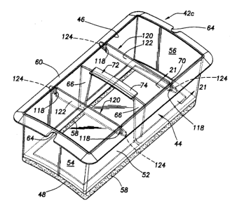
A third alternate embodiment 42c of the previously described foam dam 42,
and associated portions of the embodiment 42c, are illustrated in FIGS. 19 and
20.
Foam dam 42c is identical to the previously described foam dam 42a with the
exceptions that (1 ) the rectangular side wall openings 94 used in the foam
dam
42a are replaced in the foam dam 42c with narrow, vertically oriented slits
118
(sae FIG. 19), and (2) the foam dam 42c is provided with two modified separate
1o snap-in lockinglforce exerting structures 120 (see FIG. 20) used in place
of the
previously described locking force exerting structures 96 incorporated in the
foam
dam 42a.
With reference now to FIGS. 20 and 21, each of the two fockinglforce
exerting members 120 is of a molded plastic construction and has an elongated,
5 strip-like body 122 with narrower tapered end portions 124 that define a
pair of
abutment ledges 126 at their junctures at the ends of the body 122 with which
they are associated. The tapered end portions 124 are insertable outwardly
through the side wall slits 118, but the ledges 126 preclude the rest of the
either
body 122 from longitudinally passing outwardly through any of the slits 118.
o To operatively install the foam dam 42c the installer presses the foam dam
body 44 inwardly through the jacket Walt opening 40 (as previously described
for
the foam dam embodiments 42a and 42b) until the side wall slits 1 18 are
disposed
inwardly of the periphery of the jacket wall opening 40. While still holding
the
foam dam body 44 in this orientation, the installer longitudinally bows one of
the
strip-like locking/force exerting member bodies 122, places their end portions
124
in opposing pairs of the side wall slits 1 18, and then releases the bowed
body 122
to thereby permit it to straighten and drive its end portions 124 outwardly
through
their associated side wall slits 1 18. As previously mentioned, the body end
ledges
_18_
CA 02461388 2004-03-19
126 form abutments which prevent the balance of the now installed body strip
122
from passing outwardly through either of its associated side wall slits 118.
With the installer still pressing the foam dam body 44 inwardly through the
jacket opening 40, the other locking/force exerting member 120 is installed on
the
foam dam body 44 in the same manner. The installer then releases the foam dam
body 44. This causes upper edge portions of the outwardly projecting end
portions
124 of the installed lockinglforce exerting members 120 to upwardly engage the
underside of the jacket wall 20 (see FIG. 21 ) in a manner holding the outer
side
sealing lip 60 in it outwardly deflected, sealing engagement with the outer
side
surface of the jacket wall 20 and at the same time holding the lower side
seating
strip 58 in a compressed, seating engagement with the outer side surface of
the
tank 12 around the outwardly projecting portions of the electrical components
30,32. Once installed, the foam dam 42c functions in essentially the same
manner, and provides essentially the same advantages, as the previously
described
~ 5 insertlfoam dam 42.
A fourth alternate embodiment 42d of the previously described foam dam 42
is perspectively illustrated in FIGS. 22-22B. In the foam dam embodiment 42d,
the
rectangular molded plastic body 44 which circumscribes the axis A is of a two
piece, snap-together construction in which the body 44 comprises an axially
outer
?o portion 44a (see FIG. 22A) having the open outer side 46 and the axially
inwardly
sloped peripheral sealing lip 60 formed thereon, and an axially inner portion
44b
(see FIG. 22B) to the open inner side 48 of which the resilient seating strip
58 is
secured. Projecting axially inwardly from the periphery of the open outer side
46
(see FIG. 22A) of the outer portion 44a are a circumferentially spaced series
of
5 resilient locking tabs 128 having tapered, laterally enlarged axially inner
end
portions 130.
The interior of the axially inner body portion 44b is braced with a spaced
plurality of vertically elongated ribs 66, and laterally upturned bracing
flanges 132
formed on the internal flange 70 along central portions of the body side walls
50
-19-
CA 02461388 2004-03-19
and 52. Ribs 66 include adjacent rib pairs 66a,66a between axially outer end
portions of which joining bars 134 extend to form therewith locking recesses
136.
As best illustrated in FIG. 22b, the open upper side of the axially inner body
portion
44b has a rectangular edge periphery 138. Elongated force exerting plates 140,
in
which the arcuate end notches 64 are formed, project outwardly from the end
wails 54,46 of the inner body portion 44b. Plates 140 are axially inset from
the
edge periphery 138, and are braced to the end walls 54,56 with suitable
underside
gussets 142.
The two piece snap-together foam dam 42d is operatively installed on the
water heater 10 (as shown in simplified form in F1G. 22) by first axially
inserting
the inner body portion 44b inwardly through the jacket opening 40 in a manner
such that the inner side sealing strip 58 is compressed against the tank 12,
with
the rectangular periphery 138 of the inner body portion 44b complementarily
received in and upwardly extending through the jacket opening 40, and the
force
exerting projections 140 underlying and forcibly engaging inner side portions
of the
jacket wall 20. This initial insertion of the inner body portion 44b through
the
jacket wall opening 40, which locks the body portion 44b in place within the
insulation space 22 and maintains the sealing strip 58 in compression against
the
tank 12, is facilitated using the narrow handle structure 72 and tilting the
body
portion 44b endwise as it is initially inserted through the jacket opening 40
until
both projections 140 underlie the jacket wall 20, and then allowing the body
portion peripheral edge portion 138 to pop-up through the complementarily
sized
jacket opening 40.
Next, the outer body portion 44a is snapped into place onto the now
?5 installed inner body portion 44b by simply telescoping an inner side
portion of the
outer body portion 44a into the inner body portion 44b and forcing the locking
tabs
128 on the outer body portion 44a downwardly into associated ones of the
locking
recesses 136 until the tapered tab portions 130 snap into place beneath the
joining
bars 134, This locks the outer body portion 44a onto the inner body portion
44b in
-20-
CA 02461388 2004-03-19
a manner axially outwardly deforming the sealing lip 60 into sealing
engagement
with an outer side surface portion of the jacket wall 20 around its opening 40
and
protectively isolating electrical or other components surrounded by the
installed
foam dam 42d from foam injected into the water heater insulation space 22 as
previously described herein. As can be seen, in this embodiment 42d of the
foam
dam the projections 76a and the interfitting tabs 128 and locking recesses 136
collectively define locking and force exerting structures that lock the
installed foam
dam 42d in place on the water heater 10 and maintain the sealing elements 58
and
60, respectively, in operative sealing engagement with the tank 12 and jacket
20.
A fifth alternate embodiment 42e of the previously described foam dam 42 is
perspectively illustrated in FIGS. 23-23B. Foam dam embodiment 42e is
substantially identical in construction, installation and operation to the
previously
described two piece snap-together foam dam embodiment 42d with the following
noted exceptions.
In the foam dam embodiment 42e illustrated in FIGS. 23-23B, the axially
outer body portion 44a' has an elongated central reinforcing plate 144
longitudinally extending across the open outer side 46 of the outer body
portion
44a' between the longer side portions of the lip 60. Depending from the plate
144, and defining a slot 146 therebetween, are a pair of flanges 148 (see FIG.
23A1. The inner body portion 44b' has a modified handle structure 72a (see
FIG.
23B~ in which the previously described handle plate 74 is positioned on the
underside of the rib joining web 68.
The modified two piece snap-together foam dam 42e is installed on the
water heater 10 in the same manner as that previously described for the foam
dam
embodiment 42d. However, when the outer body portion 44a' is snapped onto the
previously inserted inner body portion 44b', the joining web 68 of the
modified
handle structure 72a (see FIG. 23B? is complementarily and interlockingly
received
in the overlying slot 146 (see FIG. 23a) beneath the reinforcing plate 144 to
-21-
CA 02461388 2004-03-19
thereby further brace the assembled foam dam 42e against undesirable
deflections
caused by foam insulation injection pressure forces exerted thereon.
While the foregoing representative foam dam embodiments have been
illustrated and described as being used in conjunction with an electric water
heater,
it will readily be appreciated by those of skill in this particular art that
they could be
also advantageously utilized with fuel-fired water heaters as well as with
various
other types of foam insulated liquid heating apparatus. Additionally, while
the
foam dam embodiments have been illustrated and described as being utilized in
the
shielding of electrical components, they could also be used in the shielding
of a
variety of other types of structures (such as pipe couplings or other
mechanical
structures) projecting outwardly from the tank 12 or other type of fluid
containing
vessel into the insulation space 22. Further, white the shapes of the
illustrated
foam dam embodiments are representatively rectangular they could, of course,
have a variety of other shapes including, but not limited to, round, square
and other
~ 5 polygonal shapes if desired or necessary.
The foregoing detailed description is to be clearly understood as being given
by way of illustration and example only, the spirit and scope of the present
invention being limited solely by the appended claims.
-22-