Note: Descriptions are shown in the official language in which they were submitted.
CA 02461643 2004-03-25
WO 03/026514 PCT/US02/30861
METHODS AND INSTRUMENTATION FOR VERTEBRAL
INTERBODY FUSION
Cross-References to Related Applications:
The present application is a continuation-in-part of U.S. Patent Application
Serial
No. 09/756,492 filed January 8, 2001, which is a continuation-in-part of U.S.
Patent
Application Serial No. 09/498,426, filed February 4, 2000, which claims the
benefit of the
filing date of Provisional application Serial No. 60/118,793, filed February
4, 1999.
BACKGROUND OF THE INVENTION
The present invention relates generally to surgical procedures for spinal
stabilization
and more specifically to instrumentation adapted for inserting a spinal
implant within the
intervertebral disc space between adjacent vertebra. More particularly, while
aspects of the
invention may have other applications, the present invention is especially
suited for disc
space preparation and implant insertion into a disc space from an anterior
surgical approach
to the spine.
Various surgical methods have been devised for the implantation of fusion
devices
into the disc space. Both anterior and posterior surgical approaches have been
used for
interbody fusions. In 1956, Ralph Cloward developed a method and
instrumentation for
anterior spinal interbody fusion of the cervical spine. Cloward surgically
removed the disc
material and placed a tubular drill guide with a large foot plate and prongs
over an
alignment rod and then embedded the prongs into adjacent vertebrae. The drill
guide
served to maintain the alignment of the vertebrae and facilitated the reaming
out of bone
material adjacent the disc space. The reaming process created a bore to
accommodate a
bone dowel implant. The drill guide was thereafter removed following the
reaming
process to allow for the passage of the bone dowel which had an outer diameter
significantly larger than the reamed bore and the inner diameter of the drill
guide. The
removal of the drill guide left the dowel insertion phase completely
unprotected.
CA 02461643 2004-03-25
WO 03/026514 PCT/US02/30861
2
More recent techniques have advanced this concept and have provided further
protection for sensitive tissue during disc space preparation and dowel
insertion. Such
techniques have been applied to an anterior approach to the lumbar spine.
An initial opening or openings are made in the disc space and the height of
the disc
space is distracted to approximate normal height. Typically, a first
distractor is inserted with
a height estimated by radiological examination. If additional distraction is
required, the first
distractor is removed and a second, larger distractor is inserted. However,
since the
positioning of the distractors is performed without the benefit of protective
guide sleeves, the
switching of distractors increases the potential for damage to neurovascular
structures and
may correspondingly increase the time of the procedure.
For bilateral procedures, a double barrel sleeve may be inserted over the
distractors,
with a central extension extending into the disc space to maintain
distraction. One limitation
on guide sleeve placement is the amount of neurovascular retraction that must
be achieved to
place the guide sleeves against the disc space. For some patients, a double
barrel sleeve may
not be used because there is insufficient space adjacent the disc space to
accept the sleeve
assembly. Thus, there remains a need for guide sleeves requiring less
neurovascular
retraction for proper placement and providing greater protection to adjacent
tissue.
While the above-described techniques are advances, improvement is still needed
to
reduce the procedure time by utilization of improved instruments and
techniques, to reduce
the potential for damage to sensitive tissue adjacent the disc space, and to
limit the amount of
vessel retraction necessary to utilize the protective instrumentation. The
present invention is
directed to this need and provides more effective methods and instrumentation
for achieving
the same.
SUMMARY OF THE INVENTION
The present invention relates to methods and instrumentation for vertebral
interbody fusion. The instruments include distractors having tips inserted
into the disc
space that conform to the anatomical conftguration of the disc space. Such
distractors are
self centering in the disc space both laterally and in the cephalad/caudal
directions, and
better maintain their position after insertion. Thus, subsequent procedures
performed in
the disc space based upon positioning of the distractors are more symmetrical
about the
spinal column axis and also more uniform between the adjacent vertebral
endplates.
CA 02461643 2004-03-25
WO 03/026514 PCT/US02/30861
3
In another aspect of the invention, a surgical instrument assembly for
distracting a
spinal disc space is provided. The assembly includes a first distracter that
has a first shaft
extending between a proximal end and a distal end and a first distracter tip
defining a
distraction height that extends from the distal end of the first shaft. The
assembly further
includes a second distracter having a second shaft extending between a
proximal end and a
distal end and a second distracter tip extending defining a distraction
height. Each of the
first and second distracter tips are self centering in the disc space both
laterally and in the
cephalad/caudal directions, and better maintain their position after
insertion. In one
embodiment, there is provided a guide sleeve having a working channel
extending
between a proximal end and a distal end the sleeve. The first and second
distracters are
received in the working channel of the guide sleeve.
Related objects, advantages, aspects, forms, and features of the present
invention will
be apparent from the following description.
BRIEF DESCRIPTION OF THE DRAWINGS
Fig. la is a perspective view of a distracter according to the present
invention.
Fig. 1b is an enlarged front view of the tip of the distracter of Fig. 1 a.
Fig. 1 c is an enlarged side view of the tip of the distracter of Fig. 1 a.
Fig. 2a is a perspective view of a distracter according to another aspect of
the present
invention.
Fig. 2b is an enlarged front view of the tip of the distracter of Fig. 2a.
Fig. 2c is an enlarged side view of the tip of the distracter of Fig. 2a.
Fig. 3 is a perspective view of a guide sleeve according to another aspect of
the present
invention.
Fig. 4 is a front view of the guide sleeve of Fig. 3.
Fig. 5 is a side view of the guide sleeve of Fig. 3.
Fig. 6 is a perspective view of a guide sleeve assembly according to another
aspect of
the present invention.
Fig. 7 is an enlarged end view of the distal end of the guide sleeve assembly
of Fig. 6.
Fig. 8 is an enlarged end view of the proximal end of the guide sleeve
assembly of Fig.
6.
CA 02461643 2004-03-25
WO 03/026514 PCT/US02/30861
4
Fig. 9 is an anterior to posterior view of a guide sleeve assembly according
to Fig. 3,
the guide sleeve assembly is positioned in relation to a pair of adjacent
vertebral bodies and
blood vessels.
Fig. 10 is a partial cross-sectional view of the disc space through line 10-10
of Fig. 9.
Fig. 11 is a perspective view of the guide sleeve assembly during insertion of
the
distractors into the disc space.
Figs. l la and l 1b are front and rear elevation views, respectively, of a
distractor driver
cap for driving the distractors into the disc space.
Figs. 12a-12b are perspective views of the guide sleeve assembly 150 with an
impactor
cap disposed thereon prior to seating the guide sleeve.
Figs. 13 is a perspective view of the guide sleeve assembly with an impactor
cap
disposed thereon.
Fig. 14 is a perspective view of the guide sleeve assembly with a slap hammer
disposed
on one of the distractors.
Figs. 15a-15b are a perspective view and an end view, respectively, of the
guide sleeve
assembly with a distractor removed.
Figs. 16a-16b are a perspective view and an end view, respectively, of the
guide sleeve
assembly with a reamer disposed adjacent a distractor.
Figs. 17a-17c are a perspective view, detail view and end view, respectively,
of the
guide sleeve assembly with a tap disposed adjacent a distractor.
Figs. 18a-18c are a perspective view, detail view and end view, respectively,
of the
guide sleeve assembly with an implant disposed adjacent a distractor.
Figs. 19a-19c are perspective views and an end view, respectively, of the
guide sleeve
assembly showing withdrawal of the other distractor.
Figs. 20a-20b are a perspective view and an end view, respectively, of the
guide sleeve
assembly with a reamer disposed adjacent an implant.
Figs. 21 a-21 c are a perspective view, detail view and end view,
respectively, of the
guide sleeve assembly with a tap disposed adjacent an implant.
Figs. 22a-22c are a perspective view, detail view and end view, respectively,
of the
guide sleeve assembly with an implant disposed adjacent an implant.
CA 02461643 2004-03-25
WO 03/026514 PCT/US02/30861
Fig. 23a is an elevational view of another embodiment first distractor
according to the
present invention.
Fig. 23b is an elevational view of the distractor of Fig. 23a rotated 90
degrees about its
longitudinal axis.
5 Fig. 23c is a right end view of the distractor of Fig. 23b.
Fig. 24a is an elevational view of another embodiment second distractor
according to
the present invention.
Fig. 24b is an elevational view of the distractor of Fig. 24a rotated 90
degrees about its
longitudinal axis.
Fig. 24c is a right end view of the distractor of Fig. 24b.
Figs. 25a and 25b show the assembly of the distractors of Figs. 23a-c and
Figs. 24a-c in
side-by-side relation.
Fig. 26a is an elevational view another embodiment guide sleeve according to
the
present invention.
Fig. 26b is an elevational view in partial section of the guide sleeve of Fig.
26a rotated
90 degrees about its longitudinal axis.
Fig. 26c is a left end view of the guide sleeve of Fig. 26b.
Figs. 27a and 27b are a top perspective view and a bottom perspective view of
a
distractor driver cap according to a further aspect of the present invention.
Fig. 27c is a cross-sectional view taken through line 27c-27c of Fig. 27a.
Fig. 27d is a left end elevational view of the distractor driver cap of Fig.
27a.
Fig. 28 shows a distractor assembly secured to the distractor driver cap of
Figs. 27a-
27d.
Fig. 29 is an elevational view of a reamer having application in the present
invention.
Fig. 30a is an elevational view of reamer plug according to another aspect of
the
present invention.
Fig. 30b is a left end view of the reamer plug of Fig. 30a.
Fig. 31 is an elevational view of an implant adjuster having application in
the present
invention.
Fig. 32a is an elevational view of an implant holder according to the present
invention.
CA 02461643 2004-03-25
WO 03/026514 PCT/US02/30861
6
Fig. 32b is an elevational view of the implant holder of Fig. 32a rotated 90
degrees
about its longitudinal axis.
32a.
Fig. 33 is an elevational view of an outer sleeve for receiving the implant
holder of Fig.
Fig. 34 is a perspective view of a wrench usable with the outer sleeve and
implant
holder shaft of Figs. 33 and 32a, respectively.
Figs. 35a-35c illustrate various steps in locating and marking the midline of
the disc
space at a subject vertebral level.
Figs. 36a-36c illustrate various steps in performing a discectomy at the
subject
vertebral level.
Fig. 37 is a perspective view of a starter distractor set with various sized
distractor tips
for use therewith.
Fig. 38 illustrates insertion of a distractor/guide sleeve assembly into the
disc space
with the distractor driver cap of Figs. 27a-27d secured thereto.
Fig. 39 illustrates insertion of the guide sleeve into the disc space using an
impactor
cap.
Figs. 40a-40c illustrate removal of a first distractor from the guide sleeve
after insertion
of the distractor/guide sleeve assembly into the disc space.
Figs. 41a-41b illustrate reaming a first implant insertion location in the
disc space
through the guide sleeve.
Figs. 42a-42b illustrate insertion of a reamer plug in the reamed first
implant insertion
location and reaming a second implant insertion location in the disc space
through the guide
sleeve.
Figs. 43a-43b illustrate securement of an implant to the implant holder of
Fig. 32a
using the driver sleeve.
Figs. 44a-44c illustrate insertion of the implant into the second implant
insertion
location in the disc space through the guide sleeve.
Fig. 45 illustrates implants inserted into the disc space at the first implant
location and
the second implant location.
Fig. 46 is a perspective view of a distractor tip according to another aspect
of the
present invention.
CA 02461643 2004-03-25
WO 03/026514 PCT/US02/30861
7
Fig. 47 is a plan view of the distractor tip of Fig. 46.
Fig. 48 is a cross-sectional view through line 48-48 of Fig. 47.
Fig. 49 is an elevational view of the lateral side of the distractor tip of
Fig. 46.
Fig. 50 is an elevational view of the medial side of the distractor tip of
Fig. 46.
Fig. 51 is a cross-sectional view through line 51-51 of Fig. 50.
Fig. 52 is an elevational view of the proximal end of the distractor tip of
Fig. 46. ,
Figs. 53a-53c illustrate an axial view, an anterior-posterior view, and a
lateral view of a
pair of vertebral bodies and the spinal disc space therebetween.
Fig. 54 is an axial view of a spinal disc space with the distractor tip of
Fig. 46
positioned therein.
Fig. 55 is an elevational view looking in the anterior to posterior direction
of a spinal
disc space with the distractor tip of Fig. 46 positioned therein.
Fig. 56 is an elevational view looking in the medial to lateral direction of a
spinal disc
space with the distractor tip of Fig. 46 positioned therein.
DESCRIPTION OF THE PREFERRED EMBODIMENTS
For the purposes of promoting an understanding of the principles of the
invention,
reference will now be made to the embodiments illustrated in the drawings and
specific
language will be used to describe the same. It will nevertheless be understood
that no
limitation of the scope of the invention is thereby intended, such alterations
and further
modifications in the illustrated device, and such further applications of the
principles of the
invention as illustrated therein being contemplated as would normally occur to
one skilled in
the art to which the invention relates.
The present invention relates to methods and instrumentation for perfornling
vertebral
interbody fusion. Specifically, although aspects of the present invention may
have other uses
either alone or in combination, the instruments and methods disclosed herein
are particularly
useful for anterior lumbar interbody fusion. However, the surgical instruments
and methods
according to the present invention are not limited to such an approach, and
may find
application in, but without limitation, lateral and anterior-lateral
approaches to the spine as
well. Also, the surgical instruments and methods of the present invention may
find
application at all vertebral segments of the spine, and in areas other than
spinal surgery.
CA 02461643 2004-03-25
WO 03/026514 PCT/US02/30861
8
Referring now to Figs. 1 a-c, there is shown a convex or first disc space
distractor 50
according to one aspect of the present invention. Distractor 50 includes a
proximal end 53
configured for engagement with conventional tools and handles (not shown) used
in operative
procedures on the spine. A shaft 54 is joined with a distractor tip 56. In the
illustrated
embodiment, shaft 54 has a hollow 'interior and a clip hole 55 communicating
with the hollow
interior; however, the present invention also contemplates a solid shaft 54.
Also, while an
integral shaft and head are shown, head 56 may be removably attached to shaft
54. One such
removable attachment is more fully disclosed in U.S. Patent Application
entitled METHOD
AND INSTRUMENTATION FOR VERTEBRAL INTERBODY FUSION, Serial No.
09/287,917, filed April 7, 1999, which is incorporated herein by reference in
its entirety
(hereinafter referred to as the '917 patent application.) Distractor tip 56 is
designed such that
it can be inserted in a disc space to establish a first working distraction
height 72 (see Fig.
1b). More specifically, distractor tip 56 has a rounded leading edge 62 that
extends to
opposing inclined surfaces 58 and 59, which in turn extend more proximally and
blend into
substantially planar opposing surfaces 60 and 61, respectively. Extending
between planar
surfaces 60 and 61 and proximal the rounded tip 62 are opposite convex
surfaces 64 and 66.
Planar surfaces 60 and 61 extend in a substantially parallel alignment along a
longitudinal axis A of distractor 50 and define height 72 therebetween. It
should be
understood that the inclined surfaces 58 and 59 cooperate to aid insertion of
the distractor tip
56 into the disc space and to initially distract the disc space to at least a
height 72. If first
distraction height 72 is sufficient, further procedures as known in the art
may then be carried
out to accomplish implant insertion. While a specific distractor has been
described in detail,
it is contemplated that other known distractor configurations may be
substituted for the same
without deviating from the scope of this invention.
Referring now to Figs. 2a-c, there is shown a second disc space distractor 80
according
to one aspect of the present invention. Distractor 80 includes a proximal end
83 configured
for engagement with conventional tools and handles (not shown). A shaft 84 is
joined with a
distractor tip 86. In the illustrated embodiment, shaft 84 has a hollow
interior and a hole 85
communicating therewith. While an integral shaft and head are shown, head 86
may be
removably attached to shaft 84, as similarly described with respect to the
removable
attachments disclosed in the '917 patent application. Similar to distractor
tip 56 of distractor
CA 02461643 2004-03-25
WO 03/026514 PCT/US02/30861
9
50, distractor tip 86 is designed such that it can be inserted in a disc space
to establish a first
working distraction height 72' (see Fig. 2b) that is preferably the
substantially the same as
working height 72. More specifically, distractor tip 86 has a rounded leading
edge 92 that
extends to opposing inclined surfaces 88 and 89 which, in turn, extend more
proximally and
blend into substantially planar opposing surfaces 90 and 91, respectively.
Planar surfaces 90 and 91 extend substantially parallel to longitudinal axis B
of
distractor 80 to define height 72' therebetween. Extending between planar
surfaces 90 and
91 are convex surface 94 and a recessed area defined by opposite concave
surface 96. Along
the distractor shaft 84, there is defined a concave surface 98 that is
adjacent to and coplanar
with concave surface 96 of distal tip 86 to define a concave surface extending
along the
length of distractor 80. In the illustrated embodiment, surface 98 has a slot
87 formed therein
communicating with the hollow interior of shaft 84; however, it the present
invention also
contemplates a solid shaft 84 and a shaft 84 without slot 87. As explained
more fully below,
concave surfaces 96, 98 are configured to receive convex surface 64 or 66 of
distractor 50 to
reside therein when distractors 50 and 80 are disposed in side-by-side
relation. Concave
surfaces 96, 98 also partially define a working space that allows operative
procedures to be
performed therethrough.
It should be understood that the inclined surfaces 88 and 89 cooperate to aid
insertion
of distractor tip 86 into the disc space, and to distract the disc space and
maintain disc space
distraction to at least a height 72, 72'. To further aid in distractor
insertion, in Fig. 2d there is
shown a distractor clip 75 having a cross member 76 with first clip member 77
and second
clip member 78 extending therefrom. Clip members 77 and 78 are each received
in a
corresponding one of holes 55 and 85 to couple distractor 50 to distractor 80.
Clip 75
prevents splaying and maintains the relative positioning of distractors 50, 80
during insertion
into the disc space. If first distraction height 72 is sufficient, further
procedures as known in
the art may then be carried out to accomplish implant insertion. It should be
further
understood that second distractor 80 has a second width 74 that is less than a
first width 70 of
first distractor 50.
Specifically, but without limitation, the distractor heads 56, 86 may be
formed with
heights 72 ranging from 6mm to 24mm. Preferably, height 72 of the next sized
distractor
increases or decreases in 2mm increments. Other variations and may be provided
as long as
CA 02461643 2004-03-25
WO 03/026514 PCT/US02/30861
the working distractor height provided approximates the disc height in a
normal spine and
accommodates insertion of an implant into the disc space as more fully
described below.
Referring now to Fig. 3, there is shown a guide sleeve 100 that is useful with
the
distractors 50 and 80 described above. Guide sleeve 100 has a wall 110
defining a working
5 channel 130 having a figure eight shaped cross-section (Fig. 9) extending in
a substantially
unobstructed manner from a proximal end 102 to a distal end 104. Sleeve 100
includes upper
windows 106 and 108 formed in wall 110 on at least one side of sleeve 100 for
engagement
by a removal tool to remove sleeve 100. The sleeve 100 also includes lower
elongated
visualization window 112 centered about the longitudinal axis L with an
elongated slot 111
10 extending proximally window 112. Window 112 provides the surgeon with the
ability to
visualize the instruments inserted in guide sleeve 100 as well as the openings
in the disc
space and vertebral bodies, without entirely removing instrumentation from
guide sleeve 100.
The reduce width of sleeve 100 allows the use of one window 112 for
visualization of
implant insertion into its respective bilateral location in the disc space,
and separate windows
along each insertion path are not necessary. However, it should be understood
that any
number of visualization windows and configurations thereof are contemplated
herein, such as
those described in the '917 patent application. The present invention also
contemplates that
covers may be used for visualization windows, as described in greater detail
in the '917
patent application.
At proximal end 102 is provided a flange ring 155. Flange ring 155 strengthens
sleeve
100 and provides a load transfer member to facilitate transfer of a driving
force to sleeve 100,
as described more fully below. Adjacent distal end 104, the material thickness
along the
exterior outer edge of wall 110 is reduced in order to provide a reduced
thickness wall portion
114 and an opposite reduced thickness wall portion (not shown). The reduced
thickness wall
portions define a smaller cross-sectional area for the sleeve 100 as well as a
reduced width
extending transverse to the longitudinal axis L. The reduced cross-sectional
area and smaller
width of guide sleeve 100 reduces the amount of vasculature and neural tissue
retraction
adjacent the disc space that would otherwise be required to place a similarly
sized guide
sleeve without the width reduction.
Distal end 104 includes a pair of flanges 118 and 120 extending from wall 110
on
opposite sides of working channel 130. Flanges 118 and 120 are configured to
extend
CA 02461643 2004-03-25
WO 03/026514 PCT/US02/30861
11
partially into the disc space. Flanges 118, 120 are each formed by and are an
extension of the
corresponding reduced thickness wall portions 114 described above. In a
preferred
embodiment, flanges 118 and 120 do not provide distraction of the disc space
but are
primarily provided to protect surrounding vessels and neurological structures
from damage
during the procedures. Since the lateral flanges do not provide structural
support for
distraction, the material thickness of the flanges and adjacent side walls may
be reduced.
Additionally, distal end 104 includes spikes 122, 124, positioned between
flanges 118, 120
and a third spike 126 and a fourth spike 128 positioned opposite spikes 122,
124 between
flanges 118, 120 as shown in Fig. 7. These spikes may be urged into the bone
of the adjacent
vertebral bodies to hold guide sleeve 100 in a fixed position relative to the
vertebral bodies.
Referring to Figs. 4 and 5, guide sleeve 100 is shown in front and side views,
respectively, to further illustrate an additional aspect of the invention. A
proximal end 102
the guide sleeve 100 has a maximum width W 1. At distal end 104 of sleeve 100,
wall 110
has a reduced wall thiclaiess at side walls 114 and 113 defining a width W2
that is less than
width W 1. The side walls 113, 114 are preferably not entirely flat and have a
slight
curvature. Side walls 113, 114 provide a reduction in wall thickness of wall
110 and taper to
the full wall thickness of wall 110 at the termination of side walls 113 and
114. The
reduction in width of wall 110 decreases the amount of vasculature and neural
tissue
retraction in the area adjacent the disc space. The desirable reduction m
wicttn is
accomplished with little reduction in the required strength of the device
since distractors 50,
80 are used to distract and maintain the distraction of the vertebral bodies
instead of the
extensions or side flanges 118, 120 of guide sleeve 100.
There are also shown in Figs. 4 and 9 a first working channel portion 107,
defined
about axis Ll, and a second working channel portion 109, defined about axis
L2. These
working channel portions 107, 109 are positioned on either side of
longitudinal axis L of
sleeve 100. There is no wall or other structure separating working channel
portions 107 and
109. Working channel portion 107 is that portion of working channel 130 about
axis Ll
between longitudinal axis L and inside surface of 116 of guide sleeve 100.
Similarly,
working channel portion 109 is that portion of working channel 130 about axis
L2 between
longitudinal axis L and inside surface 116. Thus, working channel portions 107
and 109 are
CA 02461643 2004-03-25
WO 03/026514 PCT/US02/30861
12
substantially equal in area, and each has a truncated circular shape, with the
truncated
portions of each working channel 107 and 109 positioned adjacent one another.
Referring now to Fig. 6, there is illustrated a distractor/guide sleeve
assembly 150 that
includes distractors 50 and 80 disposed within working channel 130 of guide
sleeve 100 in
side-by-side relation. Distractors 50, 80 reside within sleeve 100 with each
distractor
substantially occupying all or a portion of a corresponding one of working
channel portions
107 and 109 of working channel 130. Each distractor 50, 80 extends from
proximal end 102
to distal end 104 of the guide sleeve 100. Flange ring 155 is in the form of a
flange extending
about the proximal end 102 of guide sleeve 100 and contacts a driving cap
positioned on
distractors 50, 80 in order to maintain the relative positioning between
sleeve 100 and
distractors 50, 80 during insertion of assembly 150.
Referring now to Fig. 7, there is illustrated an end view at distal end 104 of
the
assembly 150 showing distractors 50 and 80 in side-by-side relation. More
particularly, shaft
54 of distractor 50 is received within concave portion 98 of distractor shaft
84. As also
illustrated in this view, concave portion 96 of distractor tip 86 is
coextensive with concave
surface 98 to form a concave surface that extends the length of the distractor
80. The
concave surface of distractor 80 has a radius of curvature R that is
preferably about one half
the diameter of the cage or implant to be inserted into the disc space. For
example, an 18 mm
diameter implant requires use of a distractor 80 having a radius of curvature
R of about 9
mm.
When distractor 50 is removed from guide sleeve 100, there is defined a
cylindrical
working space through the working chaimel 130 adjacent and along the recessed
areas of
distractor 80. The cylindrical working space includes that portion of the
working channel
130 between concave surfaces 96, 98 and inside wall 116 of the guide sleeve
100. Thus, the
working space occupies substantially all of working channel portion 107, (Fig.
4) and a
portion of working channel portion 109. The area of the portion of the working
channel
portion 109 occupied by the cylindrical working space is indicated in Fig. 7
by the hatched
area A, and is hereinafter referred to as the overlap region. This overlap
region A allows
operative procedures to be performed in the working space adjacent the
distractor 80 using
conventionally sized tools and implements while providing a guide sleeve 100
of reduced
overall width. The amount of width reduction achieved is approximately the
maximum width
CA 02461643 2004-03-25
WO 03/026514 PCT/US02/30861
13
of overlap region A. It should be understood that shaft 84 need not have a
recessed area to
provide a cylindrical working space in the disc space, but rather can be
provided with a
reduced diameter or size that maintains access to the overlap region A in the
disc space.
In Fig. 8 there is shown a top view of the guide sleeve assembly 150, looking
down on
proximal ends 53, 83 of the distractors 50, 80 and the proximal end 102 of
guide sleeve 100.
In one embodiment, there is provided adjacent proximal end 53 of distractor 50
a locking
segment 140 formed with and extending from the distractor shaft 54. Locking
segment 140
has a first projection 142 and a second projection 144. First and second
projections 142, 144
are received within corresponding notches 146, 148 defined in concave surface
98 of shaft 84
of distractor 80 to prevent rotation of distractors 50 and 80 with respect to
one another. The
present invention also contemplates other mechanisms for engaging distractors
50 and 80 to
prevent rotation relative to one another. For example, the above described
distractor clip 75
can be used to couple the distractors 50, 80 together. Moreover, it is
contemplated that the
distractors 50, 80 may be inserted without any locking mechanism.
The present invention contemplates that access to the disc space has
heretofore been
provided by known surgical techniques and therefore will not be further
described herein.
The use of intraoperative templates for providing access to the disc space is
known in the art.
One example of a procedure for gaining access to the disc space is disclosed
in the '917
patent application. Another reference including techniques for template
positioning and disc
space distraction using a starter distractor to initially distract the disc
space is the surgical
technique brochure entitled Reduced Profile Instrumentation published in 1999
by Sofamor
Danek, said brochure being incorporated by reference herein in its entirety
(hereinafter the
Danek brochure.) The present invention also contemplates the use and
application of other
procedures for gaining access to the disc space in conjunction with the
procedures and
instruments discussed below as would occur to those skilled in the art. The
templates
contemplated herein define the area necessary for placement of implants and
instruments
having a specific configuration and size. While in a preferred embodiment,
templates are
provided for cylindrical implants. having diameters ranging from l6mm to 24
mm, it is
contemplated that other diameters of implant and templates for use therewith
may be used
and other shapes, such as, but without limitation, squares and rectangles.
CA 02461643 2004-03-25
WO 03/026514 PCT/US02/30861
14
Access to an anterior portion of the spinal column is achieved by known
methods.
Blood vessels, particularly the aorta, vena cava, and branches thereof are
mobilized to
provide space for bilateral implant placement. The template is inserted into
the body and
advanced until the pins are disposed adjacent a disc space. The circumference
of the template
is selected to correspond to the circumference needed for bilateral placement
of a pair of
implants. More specifically, the area of the template closely approximates the
below. In this
alternate technique, clip 75 may be used to couple distractors 50, 80 together
during insertion.
In a further variation, alternating insertion of distractors 50, 80 is not
precluded by the present
invention. However, insertion of distractors 50, 80 into area needed for
placement of the
guide sleeve disclosed herein, such as that shown in Fig. 7. It is
contemplated that a guide
sleeve 100 need not necessarily be used, and tissue to the surgical site is
retracted by other
means while the disc space is distracted by distracters 50 and 80. The
surgical procedures are
then performed in the working space defined by the distracters 50, 80 as
discussed below
without use of a guide sleeve.
Referring to Fig. 9, a cross section through guide sleeve 100, with
distracters 50, 80
removed for clarity, is provided. Sleeve 100 is inserted into a disc space D
between two
adjacent vertebra Vl and V2. Disposed adjacent guide sleeve 100 are vessels
560 and 562
graphically representing portions of the aorta or vena cava. Refernng to Fig.
10, a cross-
section through line 10-10 of Fig. 9, sleeve 100, flanges 118, 120 on guide
sleeve 100 extend
into the disc space where the surgical procedures are being performed. Flanges
118, 120 and
sleeve 100 inhibit contact between vessels and tissue surrounding the disc
space and the tools
used during the surgical procedure. Spikes 122, 124, 126, and 128 may be
inserted into the
bone of the corresponding vertebral body V1, V2.
Various tools and implements are usable with guide sleeve 100 and distracters
50, 80
disclosed herein and also within the working spaces defined by the working
channel 130 of
guide sleeve 100. Several of these tools are disclosed in the Danek brochure
and in the '917
patent application, while other tools are known to those skilled in the art to
which the present
invention relates.
In accordance with a preferred method of using the apparatus of the present
invention,
reference will now be made to Figs. 11 through 22. In Fig. 11, the sleeve
assembly is
assembled and prepared for insertion through the skin and to the disc space.
Distracter driver
CA 02461643 2004-03-25
WO 03/026514 PCT/US02/30861
cap 250 of Figs. l la and l 1b is positioned on proximal end 53, 83 of
distracters 50, 80.
Driver cap 250 includes a body 252 having T-shaped slots 253 and 254
configured to receive
flanged posts 53a and 83a of distracters 50 and 80, respectively. Opposite
slots 253, 254 are
windows 256 and 257. Preferably, the flanged portion of posts 53a and 83a
extend into a
5 corresponding one of the windows 256 and 257 and also into a corresponding
one of the
upper portions 253a and 254a of slots 253 and 254 to secure driver cap 250 to
distracters 50,
80.
In use, distracter cap 250 contacts flange ring 155 with distracters 50, 80 in
sleeve 100
such that distracter tips 56, 86 can be driven into the disc space while
flanges 118, 120
10 remain positioned outside the disc space. The driving force applied to
distracter cap 250 is
transmitted to flange ring 155, and drives sleeve 100 towards the disc space
along with
distracters 50, 80. Alternatively, if distracters 50, 80 are not positioned in
guide sleeve 100,
distracter cap 250 is secured to proximal ends 53, 83 and distracter tips 56,
86 are driven into
the disc space. Distracter cap 250 is then removed and sleeve 100 placed over
the inserted
15 distracters 50, 80 and the procedure continues as discussed the disc space
simultaneously
enables the surgeon maintain the positioning of distracters 50, 80 and control
the depth of
insertion of distracter tips 56, 86 with respect to one another.
In Fig. 12a, an impactor cap 160 is disposed about proximal end 102 of sleeve
100 over
flange ring 155. Sleeve 100 is now relatively free to move with respect to
distracters 50, 80.
A driving force is applied to impactor cap 160 to drive sleeve 100 towards the
disc space and
position flanges 118 and 120 therein adjacent the distracter tips 56, 86
already positioned into
the disc space as shown in Fig. 12b. Preferably, flanges 118 and 120 do not
distract the disc
space and prevent migration of tissue into the working space when distracter
50, 80 is
removed from sleeve 100.
As shown in greater detail and enlarged Fig. 13, impactor cap 160 is
positioned around
and contacts the flange ring 155. Flange ring 155 is preferably of uniform
size and shape for
various sized guide sleeves 100, thus providing a modular attachment to each
of the various
sized guide sleeves for a single impactor cap 160. Impactor cap 160 has a
hollow interior
161 for receiving proximal ends 53, 83. Hollow interior 161 has a depth d
sufficient to allow
movement of guide sleeve 100 into the disc space while the position of
distracters 50, 80 is
maintained.
CA 02461643 2004-03-25
WO 03/026514 PCT/US02/30861
16
In Fig. 14, a slap hammer 165 is engaged to distractor 50 in order to
withdrawal
distractor 50 from the disc space. In Fig. 15a the distractor 50 is removed
from the working
channel 130 of sleeve 110 using the slap hammer 165. The distractor tip 86 of
concave
distractor 80 remains disposed in the disc space to maintain the disc space
distraction height
during subsequent operative steps. In an alternate embodiment, it is
contemplated that shaft
84 of distractor 80 is removably connected to tip 86, in which case the shaft
may be
withdrawn while leaving tip 86 in place. In a further embodiment, shaft 84 has
a reduced size
to accommodate insertion and rotation of devices into overlap region A of the
disc space.
With a removable or smaller diameter shaft, only tip 86 requires a recessed
area.
In Fig. 15b, the withdrawn distractor 50 leaves a working space comprised of
working
channel portion 109 and an overlap portion, indicated by hatched area A. Thus,
the concave
surfaces 96, 98 of distractor 80 and inside surface 116 of sleeve 110 define a
substantially
cylindrical working space for completion of further operative procedures as
described further
below. The working space defines a substantially circular cross section along
guide sleeve
100 that is adapted for receiving surgical tools therethrough to prepare the
disc space for
insertion of an implant. The overlapping configuration of distractors 50, 80
provides a
reduced overall width for guide sleeve 100.
In Figs. 16a-16b, there is shown a reamer 170 disposed through guide sleeve
110. A
cutting head 171 has cutting edges as known in the art to ream the disc space.
As shown in
Fig. 16b, reamer 170 is positioned within the working space adjacent
distractor 80, while
distractor tip 86 maintains the disc space distraction. Concave surface 98 of
shaft 84 of
distractor 80 and the inside surface 116 of sleeve 110 acts as a guide for
insertion and/or
withdrawal of reamer 170. The depth of reaming can be controlled with a depth
stop 172 and
verified via fluoroscopy
In Figs. 17a-17c, the reamer 170 is withdrawn and replaced by a tapping tool
175 with
a head 176 to prepare the space for a threaded implant. As shown in Figs. 17b
and 17c,
tapping tool 175 is positioned within the working space adjacent the concave
distractor 80,
while distractor tip 86 maintains the disc space distraction. The concave
surface 98 of shaft
84 of distractor 80 and inside surface 116 of sleeve 110 acts as a guide for
insertion of
tapping tool 175. Tapping tool 175 has a depth stop 178 to control the tapping
depth in the
disc space. Depth and sagittal alignment can also be verified via fluoroscopy
during tapping.
CA 02461643 2004-03-25
WO 03/026514 PCT/US02/30861
17
In Figs. 18a-18c, the tapping tool 175 is withdrawn and replaced by an implant
insertion device 190 with a threaded implant 200 engaged on a distal end
thereof. Threaded
implant 200 and insertion device 190 may be any one of the types and
configuration
disclosed in a first pending PCT Application No. PCT/LTS00/00590 filed on
January 11, 2000
and a second PCT Application No. PCT/LJS00/00604, also filed January 11, 2000;
each
claiming priority to U.S. Provisional Application No. 60/115, 388, filed
January 11, 1999,
each of said above referenced PCT applications being incorporated by reference
herein in its
entirety. Further, the implants of the present invention may be ary other
known implant and
insertion device, so long as at least one implant has at least one recessed
side wall. The
implants may be formed of any biocompatible material. Concave surface 98 of
shaft 84 of
distractor 80 and inside surface 116 of sleeve 110 acts as a guide for
insertion of the implant
into the disc space.
Inserter 190 includes a thumbscrew 191 having a threaded shaft (not shown)
extending
through inserter 190 to couple implant 200 thereto via an internally threaded
opening in a
slotted end 201 (Fig. 19) of implant 200. T-handle 192 is used to rotate
implant 200 and
thread it into the disc space, as shown in the enlarged view of Fig. 18b. As
shown more
clearly in the enlarged view of Fig. 18c, implant 200 is inserted so that a
concave face 202 is
disposed toward concave surface 96 of distractor 80. This positioning of
concave face 202
can be confirmed by providing alignment markings on insertion device 190 and
sleeve 100.
Further, insertion device 190 includes countersink marking 193 to provide an
indication of
the countersink of implant 200 into the disc space. To facilitate implant
rotation, inserter 190
can be provided with a movable slide at its distal end that occupies the
recessed area of
concave surface 202 providing a round construct for threading. While implant
200 is
threaded into place, distractor tip 86 maintains the disc space distraction.
In Figs. 19a-19b, when implant 200 is placed in the desired position, and
implant
inserter 190 is removed from guide sleeve 100, distractor tip 86 is withdrawn
from the disc
space. Preferably, a slap hammer 165 is engaged to distractor 80 in order to
withdraw
distractor tip 86 from the disc space and distractor 80 from guide sleeve 100.
As shown in
Figs. 19b-19c, distractor 80 is removed from working channel 130 of sleeve
110. Implant
200 remains disposed in the disc space to maintain the disc space distraction
height during
subsequent operative steps. The withdrawn distractor 80 leaves a working space
comprised
CA 02461643 2004-03-25
WO 03/026514 PCT/US02/30861
18
of working channel portion 107 and an overlap region A. Thus, concave surface
202 of
implant 200 and inside surface 116 of sleeve 110 define a cylindrical working
space in the
disc space for further procedures as described below. The working space
defines a circular
cross section that is adapted for receiving conventionally sized surgical
tools to prepare the
disc space for insertion of a second implant adjacent implant 200, while
providing a reduced
overall width.
In Figs. 20a-20b, the above described reamer 170 is disposed through guide
sleeve 110.
Cutting head 171 has threads as known in the art to ream the disc space. As
shown in Fig.
20b, reamer 170 is positioned within the working space adjacent the concave
surface 201 of
implant 200, while implant 200 maintains the disc space distraction. The
concave surface 201
of implant 200 and inside surface 116 of sleeve 110 acts as a guide for
insertion and
operation of reamer 170.
In Figs. 21 a-21 c, reamer 170 is withdrawn and replaced by the above-
described tapping
tool 175 with head 176 to prepare the space for a second threaded implant. As
shown in Figs.
21b and 21c, head 176 of tapping tool 175 is positioned within the working
space adjacent
concave surface 201 of implant 200, while implant 200 maintains the disc space
distraction.
The concave surface 201 and inside surface 116 of sleeve 110 acts as a guide
for insertion of
tapping tool 175.
In Figs. 22a-22c, the tapping tool is withdrawn and replaced by the above
described
implant insertion device 190, with a threaded implant 210 engaged on a distal
end thereof.
Threaded implant 210 may either have a circular cross-section, such as that
shown in solid
lines in enlarged Figs. 22b and 22c, or have a cross-section identical to
implant 200 with a
concave surface 202 as shown in hidden lines. In either event, concave surface
201 of implant
200 acts as a guide for threading of implant 210 into the disc space.
If an implant like that of implant 200 is used, it is preferred to position
implant 210 so
that its concave surface 212' is disposed towards concave surface 202 of
implant 200,
forming a cavity 215' therebetween as indicated in dashed lines in Fig. 22c.
The cavity may
then be packed with bone growth promoting material. T-handle 192 is used to
rotate implant
210 and thread it into the disc space, as shown in Fig. 22b, adjacent to
implant 200. If a
circular implant similar to that shown in Fig. 22c is used, implant 210 is
nested within
CA 02461643 2004-03-25
WO 03/026514 PCT/US02/30861
19
concave surface 201 of implant 200. Bone growth material can be placed in
cavity 204 of
implant 200 and in cavity 213 of implant 210.
The present invention further contemplates instruments and methods
particularly suited
for inserting threaded fusion devices into a disc space between vertebrae from
an anterior
approach to the lumbar region of the spine. It is further contemplated that
these threaded
devices can be self tapping and tapered to establish lordosis between the
vertebral endplates
when inserted in the disc space therebetween. Examples of such cages are
provided in U.S.
Patent Nos. 5,669,909 and 5,782,919, each of which is incorporated herein by
reference in its
entirety. While the instruments and methods described below are contemplated
for use with
tapered, threaded fusion devices and for use in an anterior approach to the
lumbar region of
the spine, aspects of the instruments and methods may also ' have application
in other
approaches to the spine and in the insertion of other types and shapes of
implants into the disc
space.
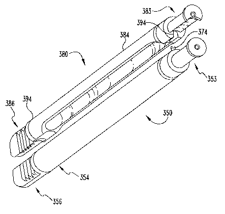
Referring now to Figs. 23a-23c, there is shown another embodiment of a convex
or first
disc space distractor 350 that is, except as described hereinbelow, similar in
many respects to
first distractor~50 of Figs. la-lc. Distractor 350 includes a proximal end
353, a shaft 354
extending along longitudinal axis Al, and a distractor tip 356 at the distal
end of shaft 354.
Proximal end 353 includes a flanged post 353a having a proximal flange 355a on
the end of
the post defining a lip 365a thereabout. A hole 367a is provided in the
proximal face of
flange 355a and configured to attach distractor 350 to conventional tools such
as a distractor
puller.
In the illustrated embodiment, shaft 354 has a hollow interior 357 to reduce
its weight;
however, the present invention also contemplates a solid shaft 354. Also,
while an integral
shaft and tip are shown, distractor tip 356 may be removably attached to shaft
354.
Distractor tip 356 can be provided with a rounded leading edge 362 that
extends
between a medial side 358 and an opposite lateral side 359 of distractor 350.
Preferably, for
reasons described further below, the transition between leading end 362 and
medial side 358
is relatively abrupt such that leading edge 362 remains extended to its most
distal-most point
at the transition therebetween. A gradual arcuate transition is provided
between lateral side
359 and leading edge 362. Distractor tip 356 also includes opposing vertebral
contacting
surfaces 360 and 361, which can each include serrations 372 to engage the
vertebral
CA 02461643 2004-03-25
WO 03/026514 PCT/US02/30861
endplates and resist movement of distractor tip 356 in the disc space.
Distractor tip 356 is
designed such that it can be inserted in a disc space to establish a
distraction height 372 (see
Fig. 23a) between the vertebral endplates. Distractor tip 356 is preferably
made from
aluminum or other radiolucent material, and includes a radiographic marker 351
to allow the
5 surgeon to determine and monitor distractor tip 356 during insertion into
the disc space.
Shaft 354 and flanged post 353a, and in the alternative tip 356, can be made
from stainless
steel or other acceptable material for surgical instruments.
Distractor 350 further includes a projection 374 that is cylindrically shaped,
although
other shapes are also contemplated, that extends medially from medial side
358. The
10 significance of projection 374 will be discussed further below. A color-
coded marker 352 is
provided in shaft 354 to give the surgeon an indication of the size of
distractor tip 356.
Referring now to Figs. 24a-24c, there is shown a second disc space distractor
380 that
is, except as described hereinbelow, similar in many respects to second
distractor 80 of Figs.
2a-2c. Distractor 380 includes a proximal end 383, a shaft 384 extending along
axis B1, and
15 a distractor tip 386 at the distal end of shaft 384. Proximal end 383
includes a flanged post
383a having a proximal flange 385a on the end of the post defining a lip 395a
thereabout. A
hole 397a is provided in the proximal face of flange 385a that is configured
to attach
distractor 350 to conventional tools such as a distractor puller.
In the illustrated embodiment, shaft 384 has a hollow interior 387 to reduce
its weight;
20 however, the present invention also contemplates a solid shaft 384. Also,
while an integral
shaft and tip are shown, distractor tip 386 may be removably attached to shaft
384.
Distractor tip 386 can be provided with a rounded leading edge 392 that
extends
between a medial side 388 and an opposite lateral side 389 of distractor 380.
Preferably, for
reasons described further below, the transition between leading end 392 and
medial side 388
is relatively abrupt such that leading edge 382 remains extended to its most
distal-most point
at the transition therebetween. A gradual arcuate transition is provided
between lateral side
389 and leading edge 392. Distractor tip 386 also includes opposing vertebral
endplate
contacting surfaces 390 and 391, which can include serrations 392 to engage
the vertebral
endplates and resist movement of distractor tip 386 in the disc space.
Distractor tip 386 is
designed such that it can be inserted in a disc space to establish a
distraction height 372' (see
Fig. 24a) between the vertebral endplates. Distractor tip 386 is preferably
made from
CA 02461643 2004-03-25
WO 03/026514 PCT/US02/30861
21
aluminum or other radiolucent material, and includes a radiographic marker 381
to allow the
surgeon to determine and monitor distracter tip 386 during insertion into the
disc space.
Shaft 384 and proximal end 386, and in the alternative tip 386, can be made
from stainless
steel or other acceptable material for surgical instruments.
Extending along medial side 388 of distracter 380 extending from leading edge
392 to
proximal flange 385 is a recessed area defined by a scalloped or concave
surface 394. In the
illustrated embodiment, concave surface 394 has a window 399 formed therein
communicating with the hollow interior 387 of shaft 384. In a manner similar
to that
discussed above with respect to distracters 50 and 80, concave surface 394
mates with the
convex medial surface 358 of first distracter 350 when distracters 350 and 380
are disposed
with medial sides 358 and 388 in side-by-side relation as shown in Figs. 25a
and 25b. Thus
distracters 350, 380 form an overall reduced width for the adjacent
distracters. The leading
ends 362, 392 form a single blunt leading end for the adjacent distracters
350, 380 when
assembled.
To aid in distracter insertion, distracter 380 includes a notch 396 fornled in
the adjacent
the proximal end of shaft 384 sized to receive projection 374 as shown in
Figs. 25a and 25b.
Notch 396 has a proximally facing opening 398 that allows projection 374 to be
top-loaded
therein from the proximal direction and withdrawn therefrom in the distal
direction when
distracters 350, 380 are adjacent one another. Projection 374 and notch 396
resist rotation of
distracters 350, 380 relative to one another and maintain the relative
positioning of distracters
350, 380 during insertion into the disc space.
Specifically, but without limitation, the distracter tips 356, 386 may be
formed with
heights 372, 372' ranging from 6mm to 24mm. Preferably, the height of the next
sized
distracter increases or decreases in 2mm increments. Other variations and may
be provided
as long as the working distracter height provided approximates the disc height
in a normal
spine and accommodates insertion of an implant into the disc space as
described herein.
Referring now to Figs. 26a-26c, there is shown a guide sleeve 400 that
receives
distracters 350, 380 described above. Guide sleeve 400 is similar to guide
sleeve 100 and can
also receive distracters 50, 80. Guide sleeve 400 has a wall defining a
working chalmel 430
having a figure eight shaped cross-section. Working channel 430 extends in a
substantially
unobstructed manner from a proximal end 402 to a distal end 404. Distal end
404 is concave
CA 02461643 2004-03-25
WO 03/026514 PCT/US02/30861
22
to match the contour of the anterior aspect of the vertebral bodies against
which it is
positioned. Sleeve 400 also includes an elongated visualization window 412
centered about
the longitudinal axis L6 with a tapered portion 411 extending proximally from
window 412
and blending into wall 410. As discussed above with respect to window 112 of
guide sleeve
100, window 412 provides the surgeon with the ability to visualize the
instruments inserted in
working channel 430 of guide sleeve 400 as well as the openings in the disc
space and
vertebral bodies.
Adjacent distal end 404, the material thickness along the lateral edge
portions wall 410
is reduced in order to provide a reduced thickness wall portion 414 and an
opposite reduced
thickness wall portion 415 in a manner similar to that discussed above with
respect to guide
sleeve 100. Guide sleeve 400 includes a pair of flanges 418 and 420 extending
from distal
end 404 on opposite sides of working channel 430. Flanges 418 and 420 are
configured to
extend partially into the disc space, and are each an extension of the
corresponding reduced
thickness wall portions 414, 415 described above. Preferably, as discussed
above with
respect to guide sleeve 100 and flanges 118 and 120, flanges 418 and 420 do
not provide
distraction of the disc space but are primarily provided to protect
surrounding vessels and
neurological structures from damage during the procedures. Since flanges 418,
420 do not
provide structural support for distraction, the material thickness of the
flanges and adjacent
side walls may be reduced.
Guide sleeve 400 also includes a first working channel portion 407, defined
about axis
L7, and a second working channel portion 409, defined about axis L8. These
working
channel portions 407, 409 are positioned on either side of longitudinal axis
L6 of sleeve 400.
There is no wall or other structure separating working channel portions 407
and 409. As
discussed above with respect to guide sleeve 100 and working channel portions
107, 109,
working channel portions 407 and 409 are substantially equal in area, and each
has a
truncated circular shape, with the truncated portions of each working channel
407 and 409
positioned adjacent one another.
A sleeve cap 455 is provided at proximal end 402 and is welded, integrally
formed
with, or otherwise attached to wall 410 of sleeve 400. Sleeve cap 455 includes
a proximal
groove 406 formed therein adjacent proximal end 402 that defines a proximal
end ring 407
around sleeve 400. Sleeve cap 455 also includes a circumferential ring member
408
CA 02461643 2004-03-25
WO 03/026514 PCT/US02/30861
23
extending therearound and positioned distally of proximal groove 406. As
described further
below, sleeve cap 455 facilitates connection of driving caps to sleeve 400 and
the assembly of
distracters 350, 380 with sleeve 400.
A side-loading distracter driver cap 550 is shown in Fig. 27a-27d. Distracter
driver cap
550 includes a body 552 having an upper portion 554 and a lower attaching
portion 556.
Attaching portion 556 has a side opening 558 that communicates with a
distracter securing
portion 560 and a sleeve securing portion 562 provided in the interior of
attaching portion
556. Distracter securing portion 560 and sleeve securing portion 562 are
configured to allow
distracter driver cap 550 to be side-loaded through side opening 558 onto the
distracter
assembly 450 (Fig. 28) to assemble distracters 350, 380 and guide sleeve 400.
Distracter securing portion 560 includes a distracter slot 564 having a first
ledge 568
therearound formed by upper extension 567. Distracter slot 564 is configured
to receive
proximal flanges 355a and 385a of flange posts 353a and 383a, respectively, of
distracters
350, 380 when positioned together as shown in Fig. 25b. Lips 365a and 395a of
flange posts
353a and 383a, respectively, contact first ledge 568 formed around distracter
slot 564.
Sleeve securing portion 562 includes a sleeve slot 566 having a second ledge
570 therearound
formed by a bottom extension 572. Sleeve slot 566 is configured to receive
proximal end
ring 407 of sleeve 400 with bottom extension 572 positioned in proximal groove
406 when
distracters 350, 380 are inserted into sleeve 400 as shown in Fig. 28.
Distracter driver cap
550 secures distracters 350, 380 together and also secured distracters 350,
380 relative to
guide sleeve 400 forniing distracter assembly 450. This allows the surgeon to
insert
distracter assembly 450 through skin and tissue to the disc space without
distracters 350, 380
and sleeve 400 moving relative to one another. Preferably, distracter tips
356, 386 extend
distally beyond the flanges 418, 420 to the distracter tips can be inserted
into the disc space
without inserting flanges 418, 420 into the disc space.
Referring to Fig. 27c, upper portion 554 is preferably solid to deliver a
driving force to
the proximal flanges 355a, 385a of distracters 350, 380 respectively. To
ensure side-loading
distracter driver cap 550 is properly positioned on distracters 350, 380, a
well 574 is provided
in upper portion 554 in communication with distracter securing portion 560. A
spring-biased
plunger 576 has a nub 578 extending into distracter securing portion 560. When
one of the
proximal flanges 355a, 385a contacts nub 578, spring 580 compresses and
plunger 576 is
CA 02461643 2004-03-25
WO 03/026514 PCT/US02/30861
24
pushed into well 574. Depending on the side from which distractor driver cap
550 is loaded,
one of the holes 367a, 397a will align with nub 578 and spring 580 pushes nub
578 into the
corresponding hole 567a, 597a. This creates a clicking sound and an audible
indication that
distractor driver cap 550 is properly seated on the distractors 350, 380.
In Fig. 29, there is shown a reamer 470 positionable through a selected one of
the
working portions 407, 409 of guide sleeve 400. Reamer 470 includes a cutting
head 471
attached to the distal end of a shaft 474. Cutting head 471 has cutting blades
476 extending
in a helical pattern from a body 478 configured to ream a cylindrical hole in
a disc space.
Body 478 has elongated openings 480 formed therethrough along each cutting
blade 476 that
communicate with a hollow interior defined by body 478. A port 482 in shaft
474 provides
access to the interior of body 478 for material removal therefrom. An opening
(not shown) in
the distal end of body 478 can also be provided for this purpose. The depth of
reaming can
be monitored and controlled with a depth stop, such as depth stop 172 of Fig.
16a, and depth
markings 484 on shaft 474. A connector 486, such as a Hudson type connector,
is provided
' at the proximal end of shaft 474 for connection with a T-handle driving
tool.
Referring now to Figs. 30a-30b, a reamer plug 600 is illustrated. Reamer plug
600 has
a shaft 602 and a plug 604 at the distal end of shaft 602. A handle 606 is
provided at the
proximal end of shaft 602. Shaft 602 is generally cylindrical but includes a
concave surface
612 extending along a medial side thereof to accommodate rotation of a tool
therebeside.
Handle 606 has a scalloped portion 608 connected to shaft 602. Scalloped
portion 608 has a
cavity 614 formed around shaft 602 that receives the proximal end of guide
sleeve 400 when
reamer plug 600 is fully inserted therein to clock shaft 604 against the
sidewall of guide
sleeve 400. Handle 606 further includes a laterally extending portion 610 that
extends away
from shaft 602 opposite concave surface 612 that facilitates insertion and
removal of plug
604 into the reamed disc space location. The scalloped portion 608 and
laterally extending
portion 610 provide clear access to one of the working channel portions 407,
409 of guide
sleeve 400 when reamer plug 600 is disposed in the other working channel
portion 407, 409.
Referring now to Fig. 31, there is shown an implant adjuster 620. Implant
adjuster 620
has a shaft 622 extending between a proximal end 624 and a distal end 626. As
discussed
further below, distal end 626 has an implant engaging portion 628 configured
to engage an
implant that has been implanted into the disc space to provide adjustment of
the final
CA 02461643 2004-03-25
WO 03/026514 PCT/US02/30861
alignment of the implant. Proximal end 624 can be provided with a Hudson-type
connector
connectable to a T-handle or the like to apply a rotational force to the
implant through
implant adjuster 600.
Referring now Figs. 32a-32b, there is illustrated an implant holder 650.
Implant holder
5 650 includes a shaft 652 extending between a proximal 654 and a distal end
656. Shaft 652
includes a threaded portion 664 adjacent proximal end 654. Distal end 656
includes an
implant engaging portion having a pair of fingers 658 extending from an end
section 668. A
shoulder 666 is provided between a tapered section 662 and end section 668.
Projections 672
extend distally from a distal end wall of end section 668. A slit 670 extends
between the
10 projections 672 proximally along the center axis C of implant holder 650
for a distance d,
biasing implant holder 650 to a position that is disengaged with the implant.
Flats 674 are
provided adjacent the proximal end of shaft 652 to provide an indication of
the orientation of
ftngers 658.
Referring now to Fig. 33, an implant driver sleeve 680 is provided. Driver
sleeve 680
15 includes a cylindrical member 682 having a hollow interior sized to receive
implant holder
650 therethrough. Cylindrical member 682 includes threads (not shown) formed
in its hollow
interior configured to mate with threads 664 on implant holder 650.
Cylindrical member 682
has a proximal end 684 with a hex nut 686 secured thereto. Cylindrical member
682 further
includes a distal end 688 having a bushing 690 secured thereto. It is
preferred that bushing
20 690 is made from a lubricious plastic material such as DELRIN and is press
ftt onto distal
end 688. In Fig. 34, a wrench 695 is provided with a handle 696 and an open-
sided hex
driving head 697 sized to engage hex nut 686 of implant driver sleeve 680.
Implant holder
650 has a sufficient length such that distal end 656 extends distally from
distal end 688 of
driver sleeve 680, and proximal end 654 of implant holder 650 extends
proximally from
25 proximal end 684 of driver sleeve 680.
To secure an implant 800 to implant holder 650 as shown in Figs. 43a-
43b,implant
holder 650 is placed through driver sleeve 680 and secured thereto by
partially mating the
proximal end of threads 664 onto the distal end of the inner thread of
cylindrical member
682. A T-handle 674 is secured to a connector at proximal end 654 of implant
holder 650.
Implant 800 is held in position by a vise and the implant can be pre-packed
with bone growth
material through a proximal end opening of the implant. Implant holder 650 is
then
CA 02461643 2004-03-25
WO 03/026514 PCT/US02/30861
26
positioned with fingers 658 around implant 800, and projections 672 can be
received in the
end opening of the implant. Preferably, ftngers 658 are configured to mate
with flats or other
surfaces provided on the sidewalk of implant 800. Implant holder 650 is
threaded proximally
with respect to driver sleeve 680 so that bushing 690 contacts tapered portion
662, and
tapered portion 662 is pulled proximally into the distal end opening of driver
sleeve 680.
Implant holder 650 can be held to prevent its rotation with handle 674 while
driver sleeve 650
is rotated with wrench 695. The force exerted on tapered portion 662 of
implant holder 650
moves implant holder 650 to an engaged position with the implant 800 by
causing slit 670 to
narrow and fingers 658 to be pushed towards one another to firmly grip implant
800
therebetween. Plastic bushing 690 prevents januning of implant holder 650 with
driver
sleeve 680, and also facilitates disassembly of outer sleeve 680 from implant
holder 650 to
release implant 800 after implant 800 is inserted in the disc space.
Referring now to Figs. 35a to 45, an example of a preferred surgical technique
employing the instruments of Figs. 23a-34 in an anterior approach to the spine
to insert a first
implant 800 and a second implant 800' bi-laterally in the disc space (as shown
in Fig. 45) will
now be described. It will be understood however, that the instruments of Figs.
23a-34 can
also have application in other approaches to the spine and with other types of
implants
mentioned herein.
Refernng now to Figs. 35a-35c, the disc space between the LS and S1 level of
the spine
has been accessed through an anterior exposure. The middle sacral artery is
typically ligated
and divided with this approach. It is also contemplated that the I,4-LS level
of the spine
could be accessed with the iliolumbar and segmental vessels identifted and
ligated if
necessary. The center of the disc space is identified and marked with a
template shaft 700
and centering pin 705. Accurate identification of the midline can be made with
the assistance
of anterior/posterior and lateral fluoroscopy. Marks M are made at the midline
both cephalad
and caudal to centering pin 705 on the vertebral bodies.
The centering pin 705 is then removed, and as shown in Fig, 36a an appropriate
sized
template 710 is attached to shaft 700 and positioned so that notch 712 aligns
with marks M.
The lateral margins of the block discectomy are marked by sharply incising the
annulus with
cutting instrument 715. As shown in Fig. 36b and 36c, template 710 is removed
and an en
bloc discectomy is typically performed to create an opening O that provides
adequate space
CA 02461643 2004-03-25
WO 03/026514 PCT/US02/30861
27
for insertion of distractors 350, 380. A disc material removal instrument 720,
such as a
pituitary rongeur, can be used to remove the nucleus pulposous to provide room
in the disc
space for the distractors and the implants 800. The anterior osteophytes on
the vertebral
bodies can also be removed to ensure accurate seating of the distal end of
guide sleeve 400
against the vertebral bodies. Curettes can be used to remove the cartilaginous
endplates. The
discectomy is performed under direct vision, and lateral fluoroscopy can be
used to confirm
the extent of disc removal in the posterior portion of the disc space. The
lateral margins of
the discectomy should not be exceeded so that the anterolateral annulus
remains intact to
enhance the stability of the construct.
If necessary, sequential distraction of the disc space can be carried out
using starter
distractor set 725 as shown in Fig. 37. Starter distractor set 725 includes a
number of
distractor tips of increasing height 726a, 726b, 726c, 726d attachable to
distractor handle 728.
If necessary, the distractor tips are sequentially driven into the disc space
to develop the disc
space height prior to insertion of distractor assembly 450.
Refernng now to Fig. 38, distractor assembly 450 is then assembled with
distractor
driver cap 550 as discussed above. The distractor tips of distractors 350, 380
are then
inserted into opening O with care taken to ensure distractor assembly 450 is
placed at midline
M. Distractor driver cap 550 is then impacted until the distractor tips are
fully seated in the
disc space. The radiographic markers in the tips can be used to verify
positioning during
seating. Distractor assembly 450 should remain parallel to the endplates
during seating, and
the intact anterolateral annulus will act to center the distractor assembly
450 and resist lateral
migration during impaction. The distractor driver cap 550 is then removed to
de-couple
distractors 350, 380 from guide sleeve 400.
Refernng now to Fig. 39, an impactor cap 730 is secured to guide sleeve 400
and the
guide sleeve 400 is impacted until flanges 418 and 420 are fully seated in the
disc space and
the distal end of sleeve 400 is positioned against the vertebral bodies while
distractors 350,
380 remain as positioned in the disc space with distractor driver cap 550.
Impactor cap 730 is
then removed. As shown in Fig. 40a, an instrument remover such as slap hammer
165 is
secured to first distractor 350. First distractor 350 is then removed, and a
cylindrical working
channel is provided through guide sleeve 400 to the disc space along the
recessed area
defined by concave surface 394 of second distractor 380 as shown in Figs. 40b
and 40c.
CA 02461643 2004-03-25
WO 03/026514 PCT/US02/30861
28
Refernng now to Figs. 41a and 41b, reamer 470 is positioned in the working
channel to
ream a cylindrical hole in the disc space at a first disc space location to
prepare it for insertion
of implant 800. Preferably, the reamer 470 creates a hole that is sized to
correspond to the
height of the leading end of the implant to be inserted into the disc space.
Reamer 470 is
attached to a depth stop, such as the depth stop 172 discussed above, and T-
handle 674. The
appropriate depth stop setting is selected based on preoperative templating
using axial CT or
MR images, and should reflect the length of implant 800 and the desired
countersink of
implant 800 in the disc space. The depth of reaming in the disc space can be
verified with
fluoroscopy.
Referring now to Fig. 42a reaming plug 600 is inserted intc the reamed first
disc space
location created with reamer 470. First implant 800 is preferably not inserted
into the first
disc space location after the first disc space location is reamed. The tapered
first implant 800
acts to distract the disc space to establish the lordotic angle between the
endplates. Reaming
of the second disc space location could be problematic if first implant 800
was inserted into
the first disc space location before the second disc space location is reamed.
Thus reamer
plug 600 maintains the disc space distraction while distractor 380 is removed.
Reamer 470 is
then used to ream a second disc space location adjacent the first disc space
location for
insertion of second implant 800'. Plug 604 is sized such that sufficient space
exists in the
disc space for cutting head 471 to rotate with the shaft of reamer 470
positioned along
concave surface of shaft 602. Handle 606 engages the proximal end of sleeve
400 to clock
shaft 602 against the inner side of the wall of guide sleeve 400 to keep
reamer plug 600 from
interfering with reamer 470 and also from interfering with insertion of second
implant 800'.
As discussed above, second implant 800' is engaged to an implant inserter by
engaging
the implant holder 650 to implant 800' with driver sleeve 680 as shown in
Figs. 43a and 43b.
As shown in Figs. 44a-44c, second implant 800' is threaded into the second
disc space
location with reamer plug 600 inserted at the first disc space location.
Second implant 800'
preferably includes 'self tapping threads, and is tapered to establish the
desired lordotic angle
between the endplates. After second implant 800' is inserted into the second
disc space
location, implant holder 650 and driver sleeve 680 are removed. Reamer plug
600 is
withdrawn from the first disc space location, and first implant 800 is
inserted into the first
disc space location as shown in Fig. 45 with the implant inserter. When
inserted, implants
CA 02461643 2004-03-25
WO 03/026514 PCT/US02/30861
29
800, 800' preferably are countersunk 2 to 5 millimeters from the anterior face
of the vertebral
bodies. If necessary, implant adjuster 620 can be inserted into the proximal
end opening of
the implants 800, 800' for alignment corrections. Bone growth G material can
be placed
around the implants 800, 800' in the disc space to facilitate fusion.
While the use of threaded implants has been primarily discussed for use with
the
instruments of the present invention, the present invention likewise
contemplates using push-
in type implants and/or expandable implants in the disc space with the
instruments described
herein. Also, while it is preferred that the present invention be utilized for
insertion of two
implants at bilateral locations within the disc space, insertion of a single
implant into the disc
space is also contemplated.
Of course, the present invention makes use of depth stops and other devices
for
measuring and controlling the depth of the various procedures performed in the
disc space.
These devices and procedures are more fully explained in the Danek brochure
and in the '917
patent application. Additionally, the present invention is not limited to use
with the tools and
instruments described above, and guide sleeve 100 and distracters 50, 80 may
be used with
other such devices as would normally occur to those skilled in the art to
which the invention
relates.
Distracter tips according to another aspect of the present invention will be
described
with reference to Figures 46-56. The distracter tip of Figs. 46-56 has
application with side-
by-side cylindrical distracter shafts, with side-by-side reduced profile
distracters, with first
and second distracters spaced from one another, or with a single distracter
inserted in
isolation in the disc space. Referring now to Figs. 46-52, distracter tip 900
is configured to
generally correspond to the anatomical geometry of the vertebral endplates El
and E2, and, in
particular, the endplate curvatures C1, C2 and C3, as will be described
further below.
Distracter tip 900 is self locating in the spinal disc space to the location
where its geometrical
configuration most closely matches that of the vertebral endplates, and any
tendency for
distracter tip 900 to move after it is positioned in the disc space is thus
reduced. Distracter
tip 900 can also be provided with teeth to further resist movement of
distracter tip 900 after it
is inserted in the disc space.
Distracter tip 900 includes a body 902 positionable in the spinal disc space
between
adjacent vertebrae V1, V2 as shown in Figs. 54-56. Distracter tip 900 can also
be provided
CA 02461643 2004-03-25
WO 03/026514 PCT/US02/30861
with an end wall 904 which extends from body 902 in the cephalad and caudal
directions.
End wall 904 has inner wall surfaces 904a, 904b oriented toward body 902 which
can contact
the vertebrae Vl, V2, respectively, outside the disc space to limit the
insertion depth of body
904 into the disc space as shown in Fig. 56. End wall 904 has a proximal face
904c opposite
5 inner surfaces 904a, 904b. A bore 910 is provided in distracter tip 900
extending distally
from proximal face 904c. Bore 910 can be threaded or otherwise configured to
allow
distracter tip 900 to be coupled to a distracter shaft. Removable distracter
tips provide
modularity so that various sized tips can be used with a single shaft. Such
tips can also be
color-coded so that the appropriately sized tip can be readily selected along
with the other
10 color-coded surgical instruments and implants to be used in procedures
employing that
particular tip. It is also contemplated that distracter tip 900 can be
provided without end wall
904, and a distracter shaft is coupled directly to body 902. It is ftirther
contemplated that
distracter tip 900 could be integrally formed with a distracter shaft as a
single unit.
Distracter tip 900 can be provided with distal radiographic marker 906 and one
or more
15 proximal radiographic markers 908. Radiographic markers 906, 908 can be in
the form of
stainless steel pins, balls, or other radiographic material. In the
illustrated embodiment, two
such proximal markers 908 are provided on either side of bore 910.
Radiographic markers
can be located in a horizontal plane defined by central axis 912 so that the
markers are
located in the vertical center of the disc space when distracter tip 900 is
inserted therein.
20 Distracter tip 900 can thus be made from aluminum or other radiolucent
material, and
markers 906, 908 allow the surgeon to determine the location of and monitor
insertion of
distracter tip 900 during insertion into the disc space. Also, the surgeon can
radiographically
or monitor an implant or instruments located beside distracter tip 900 without
interference
from distracter tip 900.
25 Distracter tip 900 has central axis 912 extending therethrough between a
leading distal
end 900a of distracter tip 900 and an opposite trailing proximal end 900b. As
used herein,
distal refers to a position located away from the surgeon as distracter tip
900 is inserted into
the disc space and proximal refers to the direction oriented towards the
surgeon as distracter
tip 900 is inserted in the disc space. Central axis 912 is centrally located
between a lateral
30 surface 914 and a medial surface 916 of distracter tip 900. Lateral surface
914 is positioned
adjacent to or toward the lateral edges of the vertebral endplates when
distracter tip 900 is
CA 02461643 2004-03-25
WO 03/026514 PCT/US02/30861
31
inserted in the disc space. Medial surface 916 is located adjacent to or on
the central spinal
column axis extending through the middle of the vertebral endplate when
distractor tip 900 is
inserted in the disc space.
Distractor tip 900 further includes a proximal upper surface 918 and a
proximal lower
surface 920. Each of the proximal surfaces 918, 920 extend distally from end
wall 904
toward distal end 900a to an upper distal surface 922 and a lower distal
surface 924,
respectively. In the illustrated embodiment, proximal surfaces 918, 920 extend
parallel to
central axis 912. The proximal upper and lower surfaces can include a number
of teeth 938,
940, respectively, formed thereacross between lateral surface 914 and medial
surface 916.
Teeth 938, 940 can be formed by cutting grooves in the upper and lower
proximal surfaces
918, 920. In the illustrated embodiment, teeth 938, 940 each have a sloped
distal wall and a
vertical trailing wall that join at a sharp peels. The sloped distal walls
facilitate insertion,
while the teeth and vertical proximal wall resist pullout and twisting of
distractor tip 900 in
the disc space and provide solid anchorage with respect to the vertebral
endplates. Distal
upper and lower surfaces 922, 924 are tapered toward central axis 912 from
their junction
with respective adjacent proximal upper and lower surfaces so that distractor
tip 900 has a
reduced height 926 at distal end 900a that is less than a height 928 at
proximal upper and
lower surfaces 918, 920.
In the illustrated embodiment of Fig. 51, medial surface 917 has a convexly
arcuate
profile between upper proximal surface 918 and lower proximal surface 922.
Other profile
shapes are also contemplated, including a linear medial surface or a concave
medial surface.
Distal end 900a includes a generally linear distal end surface 932 that
extends generally
transverse to central axis 912. Lateral surface 914 is described further
below.
With reference to Figs. 53a-53c, the vertebral endplate anatomical geometry
will be
discussed with reference to vertebrae Vl and V2 positioned on opposite sides
of a disc space
D. It is contemplated that vertebrae Vl, V2 form part of the lumbar or sacral
region of the
spine; however, the principles of the present invention also have application
in the cervical
and thoracic regions of the spine. Vertebra V1 has an endplate E1 and vertebra
V2 has an
endplate E2. Endplate E1 has a cortical rim around its perimeter that
surrounds a concave
portion of cancellous or thin cortical bone in the middle of endplate E1. When
distractor tip
CA 02461643 2004-03-25
WO 03/026514 PCT/US02/30861
32
900 is used in an anterior approach to the spine, distal end surface 932 is
located in the
posterior region of endplates E1 and E2 with distractor tip 900 inserted into
the disc space.
The junction of the cortical rim and concave portion of the endplate defines a
curvature
C1 in the axial plane between the lateral portion of the cortical rim and the
posterior portion
of the cortical rim. In the coronal plane of Fig. 53b, endplate E1 has an
inner cortical rim
. curvature C2 at the junction between the concave portion and the cortical
rim. In the sagittal
plane of Fig. 53c, the inner cortical rim of endplate E1 has a curvature C3 at
the junction
between the concave portion and the cortical rim along the posterior portion
of the cortical
rim. End plate E2 has inner cortical rim at the junctions between its concave
portion and
cortical rim defining similar curvatures.
As shown in Fig. 47 and Fig. 54, body 902 includes a first transition surface
930
between distal end surface 932 and lateral surface 914 having a configuration
that takes into
account the vertebral endplate anatomy. First transition surface 930 has a
curvature C1' in
the axial plane that generally conforms to curvature C 1 in the axial plane of
the inner cortical
rim where it transitions between the lateral portion of the cortical rim and
the posterior
portion of the cortical rim. In one specific embodiment, curvature C1' is
defined by a radius
of curvature of 9 millimeters.
Lateral surface 914 has a proximal portion 914a extending generally parallel
with
central axis 912. At a distance Xl from distal end surface 932, lateral
surface 914 bends at an
angle A1 from proximal portion 914a towards central axis 912 to form a tapered
portion 914c
that blends into the curved transition surface 930. In one specific
embodiment, this distance
X is 10 millimeters and angle A1 is 10 degrees. Medial surface 916 can be
similarly
configured with a taper angle A1 to form a tapered portion 916a. Medial
tapered surface
916a extends further distally than lateral tapered surface 914c,and blends
into distal end
surface 932 by radius Rl. Tapered surfaces 914c and 916a provide an overall
reduced width
at distal end 900a.
As shown in Fig. 51, lateral surface 914 has a generally linear central region
914b.
Extending from this central region between the upper and lower proximal
surfaces 918, 920
and the upper and lower distal surfaces 922, 924 are upper and lower second
transition
surfaces 934a, 934b, respectively. Second transition surfaces 934a, 934b each
have a
curvature C2' that conforms to the inner cortical rim along the lateral
portion thereof in the
CA 02461643 2004-03-25
WO 03/026514 PCT/US02/30861
33
coronal plane, such as shown in Fig. 55. Second transition surfac;,s 934a,
934b have a height
X2 from the respective upper or lower proximal surfaces to the central region
914b. In one
specific embodiment, height X2 is 3 millimeters, and curvature C2' is defined
by a radius of
curvature of 8 millimeters.
As shown in Figs. 48-49, upper and lower third transition surfaces 936a, 936b
extend
from distal end surface 932 to distal upper surface 922 and distal lower
surface 924. Upper
and lower third transition surfaces 936a, 936b also extend from first
transition surface 930 to
the respective upper and lower distal surfaces 922, 924. Third transition
surfaces 936a, 936b
have a curvature C3' that blends distal end surface 932 into the upper and
lower distal
surfaces 922, 924. As shown in Fig. 56, curvature C3' of third transition
surfaces 936a, 936b
conforms to the inner cortical rim along the posterior portion of the cortical
rim and its
transition to the lateral portion of the cortical rim. Third transition
surfaces 936a, 936b
further blend first transition surface 930 into the upper and lower distal
surfaces 922, 924. In
one specific embodiment, curvature C3' is defined by a radius of curvature of
1.5 millimeters
along distal end surface 932 and a radius of curvature of 2 millimeters along
first transition
surface 930.
Distractor tip 900 having the above features generally corresponds to the
anatomical
geometry of the vertebral endplates El and E2, and, in particular, the
endplate curvatures Cl,
C2 and C3. As such, distractor tip 900 is self locating in the spinal disc
space to the location
where its geometrical configuration most closely matches that of the vertebral
endplates.
Furthermore, upon insertion distractor tip 900 will be located in the disc
space in contact with
the inner cortical rim, and any tendency for distractor tip 900 to move
laterally or distally in
the disc space is resisted by contact between the cortical rim and body 904.
While the invention has been illustrated and described in detail in the
drawings and
foregoing description, the same is to be considered as illustrative and not
restrictive in
character, it being understood that only the preferred embodiment has been
shown and
described and that all changes and modifications that come within the spirit
of the invention
are desired to be protected.