Language selection

Search

Patent 2461681 Summary

Third-party information liability

Some of the information on this Web page has been provided by external sources. The Government of Canada is not responsible for the accuracy, reliability or currency of the information supplied by external sources. Users wishing to rely upon this information should consult directly with the source of the information. Content provided by external sources is not subject to official languages, privacy and accessibility requirements.

Claims and Abstract availability

Any discrepancies in the text and image of the Claims and Abstract are due to differing posting times. Text of the Claims and Abstract are posted:

  • At the time the application is open to public inspection;
  • At the time of issue of the patent (grant).
(12) Patent: (11) CA 2461681
(54) English Title: PINCH GRIP TYPE BOTTLE-SHAPED CONTAINER
(54) French Title: CONTENANT BOUTEILLE DE TYPE A POIGNEE
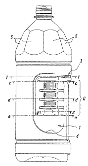
Status: Expired
Bibliographic Data
(51) International Patent Classification (IPC):
  • B65D 1/02 (2006.01)
  • B65D 1/40 (2006.01)
  • B65D 23/10 (2006.01)
(72) Inventors :
  • SAITO, HIROMICHI (Japan)
  • IIZUKA, TAKAO (Japan)
(73) Owners :
  • YOSHINO KOGYOSHO CO., LTD. (Japan)
(71) Applicants :
  • YOSHINO KOGYOSHO CO., LTD. (Japan)
(74) Agent: RIDOUT & MAYBEE LLP
(74) Associate agent:
(45) Issued: 2008-03-25
(86) PCT Filing Date: 2002-09-24
(87) Open to Public Inspection: 2003-04-03
Examination requested: 2004-03-25
Availability of licence: N/A
(25) Language of filing: English

Patent Cooperation Treaty (PCT): Yes
(86) PCT Filing Number: PCT/JP2002/009775
(87) International Publication Number: WO2003/026974
(85) National Entry: 2004-03-25

(30) Application Priority Data:
Application No. Country/Territory Date
2001-293421 Japan 2001-09-26

Abstracts

English Abstract


A bottle-shaped container according to the present invention is of pinch
grip type and includes a container body having opposed recesses formed at
sidewall
regions of a main body portion of the container body, respectively, to thereby
form a
grip part of the container by an entire region of the main body portion
between the
recesses, including the back surface region. The bottle-shaped container
further
includes a pressure-reduction absorbing panel at the back surface region,
having an
upper end arranged at a height substantially coincident with that of an upper
end of
the grip part, and steps provided along the edges of the recesses forming the
grip part,
respectively.


French Abstract

L'invention concerne un contenant bouteille de type à poignée, comportant des parties en creux dans des zones de la paroi latérale de la section cylindrique du corps, toutes les zones intermédiaires, y compris l'arrière de la section cylindrique, étant des éléments constitutifs de la poignée. La partie arrière comprend une plaque d'absorption de décompression, dont la position en hauteur de l'extrémité supérieure correspond approximativement à l'extrémité supérieure de la poignée. Les bords des parties en creux formant la poignée sont pourvus d'un étagement.

Claims

Note: Claims are shown in the official language in which they were submitted.


-5-

Claims:


1. A pinch grip type bottle-shaped container comprising a container body
having
opposed recesses formed at sidewall regions of a main body portion of the
container body,
respectively, to thereby form a grip part of the container by an entire region
of the main body
portion between the recesses, including the recesses and a back surface region
of the main
body portion, said bottle-shaped container further comprising: a pressure-
reduction
absorbing panel at said back surface region, said pressure-reduction absorbing
panel having
an upper end arranged at a height substantially coincident with that of an
upper end of said
grip part; and steps provided along the edges of said recesses forming said
grip part,
respectively.


2. The bottle-shaped container according to claim 1, wherein said container is
provided
with a lateral rib having a groove located at a boundary between (1) said
upper end of said
pressure-reduction absorbing panel in said back surface region and (2) said
main body
portion of the container body, said groove being convex inwardly of said
container.


3. The bottle-shaped container according to claim 2, wherein said container is
provided
with pressure-reduction absorbing panels at a shoulder part of the container
body, which is
contiguous with said main body portion.


4. The bottle-shaped container according to claim 1, wherein said container is
provided
with pressure-reduction absorbing panels at a shoulder part of the container
body, which is
contiguous with said main body portion.

Description

Note: Descriptions are shown in the official language in which they were submitted.


CA 02461681 2004-03-25

-1-
PINCH GRIP TYPE BOTTLE-SHAPED CONTAINER
BACKGROUND ART
Technical Field

[0001] The present invention relates to a so-called pinch grip type bottle-
shaped
container, which is formed with opposed recesses at a main body portion of the
container body such that the recesses are used as a grip part for gripping the
container, and intends to advantageously avoid lowering of the mechanical
strength
due to a light-weighted or thin-walled nature of the container.
Related Art
[0002] Synthetic resin containers, such as PET bottles, have been widely used
as
containers, e.g., for filling therein foods, beverages, cosmetics or
medicines, since
such containers are light in weight and can thus be easily handled, have
transparency
to exhibit a refined appearance comparable to glass containers, and can be
produced
at low cost.

[0003] Synthetic resin containers have a relatively low mechanical strength
against external forces. Therefore, when the container is gripped at its main
body
portion for pouring the contents out of the container, the container
inevitably
undergoes deformation at its gripped part.

[0004] It is thus a typical countermeasure to appropriately control the
container
wall thickness and form longitudinal ribs, lateral ribs or waists (i.e.,
circumferential
grooves surrounding the main body portion) so as to improve the resistances of
the
container to external forces, such as rigidity, buckling strength, etc.

[0005] However, there is an increasing demand for thin-walled (or light-
weighted) containers so as to reduce the resin amount to be used per one
container
from a standpoint of effective utilization of resources and reduction in the
amount of
wastes, resulting in a situation where the strength of the container is
inevitably
further lowered in order to deal with such a demand.

[0006] Particularly, in the case of pinch grip type large-sized containers,
which
have been recently used widely as large-sized containers having a filling
volume of
not less than 2.7 liters, for containing therein Japanese "sake", soy sauce,
edible oil,
Japanese "shochu" (distilled spirit), whisky, etc., when it is desired to
realize light-
weighted structure, the container main body portion including the grip part
inevitably


CA 02461681 2004-03-25

-2-
undergoes deformation when gripped at the grip part.
DISCLOSURE OF THE INVENTION

[0007] It is therefore an object of the present invention to provide an
improved
pinch grip type bottle-shaped container capable of retaining its initial shape
even
when the container is light-weighted and thin-walled.

[0008] According to the present invention, there is provided a pinch grip type
bottle-shaped container comprising a container body having opposed recesses
formed
at sidewall regions of a main body portion of the container body,
respectively, to
thereby form a grip part of the container by an entire region of the main body
portion
between the recesses, including the recesses themselves and a back surface
region of
the main body portion, wherein the bottle-shaped container further comprises:
a
pressure-reduction absorbing panel at said back surface region, said pressure-
reduction absorbing panel having an upper end arranged at a height
substantially
coincident with that of an upper end of said grip part; and steps provided
along the
edges of said recesses forming said grip part, respectively.
[0009] The bottle-shaped container according to the present invention may be
provided with a lateral rib having a groove located at a boundary between the
upper
end of the pressure-reduction absorbing panel in the back surface region, and
the
main body portion of the container body, so that the groove is convex inwardly
of the
container.
[0010] Furthermore, the bottle-shaped container according to the present
invention may be provided with pressure-reduction absorbing panels at its
shoulder
part.
BRIEF DESCRIPTION OF THE DRAWINGS

[0011] The present invention will be described in further detail hereinafter,
with
reference to a preferred embodiment shown in the drawings.

[0012] FIG. 1 through FIG. 3 are front view, side view and rear view,
respectively, of a bottle-shaped container according to one embodiment of the
present invention.

[0013] FIG. 4(a) and FIG. 4(b) are plan view and bottom view of the container
of FIG. 1, respectively, and FIGS. 4(c) through (g) are cross-sectional views
taken
along line c-c through line g-g of FIG. 1, respectively.


CA 02461681 2004-03-25

-3-
BEST MODE FOR CARRYING OUT THE INVENTION

[0014] In FIGS. 1 through 3, reference numerals 1 denotes recesses that are
formed in sidewall regions of a container main body portion so as to be
opposed to
each other, and reference numeral 2 denotes a pressure-reduction absorbing
panel
provided in a back surface region between the recesses 1 so as to prevent
deformation of the container due to a pressure reduction within the container.
There is formed a grip part G, by the entire region from one recess 1 to the
other
recess 1, inclusive of these recesses themselves and the pressure-reduction
absorbing
panel 2. This kind of grip part G may also be called as "pinch grip".

[0015] Furthermore, reference numeral 3 denotes a lateral rib having a groove
M
located at a boundary between the upper end of the pressure-reduction
absorbing
panel 2 and the container main body portion such that the groove is convex
inwardly
of the container, reference numerals 4 denotes steps provided along the edges
of the
recesses 1 forming the grip part G, respectively, and reference numerals 5
denotes
pressure-reduction absorbing panels, respectively, provided at a shoulder part
of the
container body.
[0016] The bottle-shaped container shown in FIG. 1 through FIG. 3 is of a
widely used type having a filling volume of 2.7 liters, and it is typical to
use about
101 grams of resin for molding such a container. However, when the used resin
amount is reduced to about 85 grams, for example, so as to reduce the weight
of such
container, the mechanical strength of the grip part G is considerably lowered
so that
the grip part G is significantly deformed when the container is gripped, and
distortion
tends to occur in the front surface of the container due to the deformation of
the grip
part G.
[0017] Nonetheless, according to the present invention, the grip part G has an
upper end GUE arranged at a height substantially coincident with that of an
upper end
2UE of the pressure-reduction absorbing panel 2 (see FIG. 3), and the lateral
rib 3 is
provided to have the groove M. Therefore, it is possible to improve the
gripping
ability, enhance the rigidity at that region, and significantly reduce the
deformation

upon gripping the grip part G. It is to be noted that the lateral rib 3 may be
omitted
when the region of the main body portion above the pressure-reduction
absorbing
panel 2 is narrow and has a shape capable of ensuring certain degree of
rigidity.
[0018] Furthermore, the steps 4 (see FIGS. 4(c) through (f)) provided along
the


CA 02461681 2004-03-25

-4-
edges of the recesses 1 exhibit functions for enhancing the rigidity of the
boundaries
between the recesses 1 and the container main body portion, thereby
restricting a
deformation of that front surface of the container body main body portion,
which, for
example, is to be adhered with a label (not shown). This is because the front
surface of the container is always kept in a tightened state, whether the grip
part is
gripped or not.

[0019] It is further possible, according to the present invention, to provide
the
pressure-reduction absorbing panels 5 at the shoulder part of the container as
shown
in the drawings. In this instance, it is possible to complement the pressure-
reduction absorbing panel 2 in such a manner as to ensure a sufficient amount
of
pressure-reduction compensation, thereby allowing the deformation of the main
body
portion to be restricted further effectively.
[0020] Although the container according to the present invention can be
advantageously obtained by a biaxial-stretching blow molding of a
thermoplastic
resin such as polyethylene terephthalate, the forming method thereof is not
particularly limited thereto.
[0021] It will be appreciated from the foregoing description that, according
to
the present invention, the mechanical strength of the container and
particularly the
rigidity of the grip part can be ensured even when the container is thin-
walled for its
reduced weight by reducing the resin amount, thereby enabling the initial
shape of
the container to be stably retained.
[0022] It is needless to say that the present invention is not limited to the
above-
mentioned embodiments, and may be carried out with numerous variants.

Representative Drawing
A single figure which represents the drawing illustrating the invention.
Administrative Status

For a clearer understanding of the status of the application/patent presented on this page, the site Disclaimer , as well as the definitions for Patent , Administrative Status , Maintenance Fee  and Payment History  should be consulted.

Administrative Status

Title Date
Forecasted Issue Date 2008-03-25
(86) PCT Filing Date 2002-09-24
(87) PCT Publication Date 2003-04-03
(85) National Entry 2004-03-25
Examination Requested 2004-03-25
(45) Issued 2008-03-25
Expired 2022-09-26

Abandonment History

There is no abandonment history.

Payment History

Fee Type Anniversary Year Due Date Amount Paid Paid Date
Request for Examination $800.00 2004-03-25
Application Fee $400.00 2004-03-25
Maintenance Fee - Application - New Act 2 2004-09-24 $100.00 2004-07-09
Registration of a document - section 124 $100.00 2005-02-16
Maintenance Fee - Application - New Act 3 2005-09-26 $100.00 2005-07-06
Maintenance Fee - Application - New Act 4 2006-09-25 $100.00 2006-06-29
Maintenance Fee - Application - New Act 5 2007-09-24 $200.00 2007-07-25
Final Fee $300.00 2008-01-08
Maintenance Fee - Patent - New Act 6 2008-09-24 $200.00 2008-08-13
Maintenance Fee - Patent - New Act 7 2009-09-24 $200.00 2009-08-13
Maintenance Fee - Patent - New Act 8 2010-09-24 $200.00 2010-08-23
Maintenance Fee - Patent - New Act 9 2011-09-26 $200.00 2011-09-06
Maintenance Fee - Patent - New Act 10 2012-09-24 $250.00 2012-08-08
Maintenance Fee - Patent - New Act 11 2013-09-24 $250.00 2013-08-14
Maintenance Fee - Patent - New Act 12 2014-09-24 $250.00 2014-09-04
Maintenance Fee - Patent - New Act 13 2015-09-24 $250.00 2015-09-02
Maintenance Fee - Patent - New Act 14 2016-09-26 $250.00 2016-09-01
Maintenance Fee - Patent - New Act 15 2017-09-25 $450.00 2017-08-31
Maintenance Fee - Patent - New Act 16 2018-09-24 $450.00 2018-08-29
Maintenance Fee - Patent - New Act 17 2019-09-24 $450.00 2019-09-04
Maintenance Fee - Patent - New Act 18 2020-09-24 $450.00 2020-09-02
Maintenance Fee - Patent - New Act 19 2021-09-24 $459.00 2021-09-01
Owners on Record

Note: Records showing the ownership history in alphabetical order.

Current Owners on Record
YOSHINO KOGYOSHO CO., LTD.
Past Owners on Record
IIZUKA, TAKAO
SAITO, HIROMICHI
Past Owners that do not appear in the "Owners on Record" listing will appear in other documentation within the application.
Documents

To view selected files, please enter reCAPTCHA code :


To view images, click a link in the Document Description column. To download the documents, select one or more checkboxes in the first column and then click the "Download Selected in PDF format (Zip Archive)" or the "Download Selected as Single PDF" button.

List of published and non-published patent-specific documents on the CPD .

If you have any difficulty accessing content, you can call the Client Service Centre at 1-866-997-1936 or send them an e-mail at CIPO Client Service Centre.


Document
Description 
Date
(yyyy-mm-dd) 
Number of pages   Size of Image (KB) 
Abstract 2004-03-25 1 18
Claims 2004-03-25 1 33
Representative Drawing 2004-03-25 1 10
Description 2004-03-25 4 202
Drawings 2004-03-25 4 49
Cover Page 2004-05-25 1 35
Cover Page 2008-03-06 1 40
Claims 2006-10-10 1 36
Representative Drawing 2008-02-28 1 8
Abstract 2008-02-28 1 18
Assignment 2004-03-25 4 118
PCT 2004-03-25 3 122
Correspondence 2004-05-20 1 26
Fees 2004-07-09 1 35
Prosecution-Amendment 2006-04-10 3 74
Fees 2007-07-25 1 29
Assignment 2005-02-16 3 90
Fees 2005-07-06 1 27
Correspondence 2007-12-11 1 52
Prosecution-Amendment 2006-01-25 1 20
Prosecution-Amendment 2006-03-16 1 24
Fees 2006-06-29 1 28
Prosecution-Amendment 2006-10-10 4 116
Correspondence 2008-01-08 1 33
Fees 2008-08-13 1 34