Note: Descriptions are shown in the official language in which they were submitted.
CA 02461754 2004-03-25
1
SPECIFICATIONS
TITLE OF THE INVENTION
Pulse Oscillating type Solid Laser Unit and Laser Process
Unit
FIELD OF THE ART
This invention relates to a pulse oscillating type
solid laser unit that preferably solves a problem of
instability in a processing and a laser process unit that
does not produce a processing defect due to fluctuation of a
laser output.
BACKGR~ ART
Recent progress of a laser diode (hereinafter noted as
an LD) excited solid laser unit body wherein its output and
luminance are highly developed makes ~.t possible for a laser
unit to conduct a precise welding processing or a fine
removal processing with high speed and high precision that
used to be impossible for a conventional process unit. Then
the laser unit is used for spot welding or seam welding of
an electric/electronic component or applied to a surface
marking or scribing processing or a drilling or cutting
processing, of metal, semiconductor or ceramics.
As a representative example of a conventional solid
laser unit, Fig. 9 shows an arrangement of a solid laser
unit that mainly comprises an LD excited pulse type Nd:YAG
laser unit body wherein a laser activated media is a rod-
type Nd:YAG crystal and a mean output is in a 300 W class.
The Nd:YAG crystal 1 whose rod diameter is 5 mm and
CA 02461754 2004-03-25
2
whose length is 116 mm is excited by LD light 3 radiated
from an LD excited unit 2 equipped with 60 bars of LDs whose
mean light output is 20 W/bar and that oscillates at a
central wavelength of 808 nm, light of 1.06 Eun irradiated
from the Nd:YAG crystal 1 is selectively amplified between a
total reflection mirror 5 and an output bond mirror 6 whose
reflection coefficient is 70 0, each of the mirrors 5, 6
constituting a laser resonator 4 whose resonator length is
400 mm, so as to be Nd:YAG laser light 7 and then the Nd:YAG
laser light 7 is radiated from the output bond mirror 6. In
addition, electricity is conducted to the LD excited unit 2
by a direct current stabilized power,supply 8 and the Nd:YAG
crystal 1 and the LD excited unit 2 are temperature-
controlled directly or through purified water supplied by a
purified water cooling system 9 to keep a temperature of its
peripheral portion constant in order to maintain an Nd:YAG
laser output stable.
In addition, a part of the Nd:YAG laser light 7 is
made to be laser light 11 for monitoring by a beam splitter
10 and permeates through a power attenuator 12 and then is
introduced into a high speed power sensor 13. Other laser
light 7 is gathered by incident gathering optical system 14
so as to meet a transmission condition of an optical fiber
15 for transmission whose core diameter is 0.3 mm and whose
length is 10 m. The laser light radiated from the optical
fiber 15 for transmission is formed or focused by radiation
gathering optical system 18 so as to be in a beam shape
appropriate for processing an object to be processed 17
CA 02461754 2004-03-25
3
placed on a CNC table 16 and then a required laser
processing is conducted.
In this arrangement, the laser light 7 is so made that
current conducted to the LD excited unit 2 from the direct
current stabilized power supply 8 is feedback-controlled so
as to coincide a laser output value monitored by the high
speed power sensor 13 with a command laser output value.
However, a conventional arrangement wherein a PIN type
Si photo diode is used as a high speed power sensor of laser
light for monitoring has following defects.
(1) Since an acceptable input light level to the power
sensor is on an mW level, actual Nd:YAG laser light is
required to attenuate to a degree of about one hundred
thousandths by the use of a high-precision power split means
in combination with a high attenuating means. However, a
power split rate and a power attenuating rate of an optical
component used as the high-precision power split means and
the high attenuating means are easily changed in its
characteristics due to humidity change or dust adhered to
the optical component, which makes it difficult to predict
actual Nd:YAG laser output accurately from the laser output
for monitoring.
(2) Since temperature anaclisis of detecting sensitivity of
the high speed power sensor is large such as 0.2 ~ 1.0 o/°C,
the detecting sensitivity easily varies due to change of
ambient temperature. Then it is difficult for the laser unit
body placed under an environment wherein ambient temperature
is not constant to predict actual Nd:YAG laser light output
CA 02461754 2004-03-25
with accuracy in a stale manner from the measured laser
output for monitoring.
As a result of this, the Nd:YAG laser unit wherein the
laser output value for monitoring measured by the high speed
power sensor is controlled as a feedback signal could not
obtain stable Nd:YAG laser output with absolute precision of
not greater than 2% due to the above-mentioned problems of
the high power sensor. Then a problem was developed that
processing defect such as accuracy defect or strength defect
was inevitable for a laser processing using the laser unit
body of the above-mentioned arrangement.
In addition, it is desired for the laser process unit
using this kind of the pulse oscillating type solid laser
unit to avoid processing defect due to fluctuation of laser
output. The following is known as this kind of a laser
process unit.
As a conventional example, Fig. 10 shows an
arrangement of an LD excited pulse type Nd:YAG laser process
unit body whose primary purpose is a laser welding
processing wherein a laser activated media is a rod-type
Nd:YAG crystal 101 and a mean output is in a 300 W class.
The,Nd:YAG crystal 101 whose rod diameter is 5 mm and
whose length is 116 mm is excited by LD light 103 radiated
from an LD excited unit 102 equipped with 60 bars of 20
Wlbar LDs that oscillates at a central wavelength of 808 nm,
light of 1.06 ~m irradiated from the Nd:YAG crystal 101 is
selectively amplified between a total reflection mirror 105
and an output bond mirror 106 whose reflection coefficient
CA 02461754 2004-03-25
is 70 0, each of the mirrors 105, 106 constituting a laser
resonator 104 whose resonator length is 400 man, so as to be
Nd:YAG laser light 107 and then the Nd:YAG laser light 107
is radiated from the output bond mirror 106. In addition,
5 the Nd:YAG crystal 101 and the LD excited unit 102 are
temperature-controlled directly or through purified water
supplied by a purified water cooling system 108 to keep a
temperature of its peripheral portion constant in order to
maintain an Nd:YAG laser output stable.
A part of the Nd:YAG laser light 107 is reflected off
a beam sputter 109, taken as monitor light 110 and
introduced into a monitor light output measuring instrument
111 of a thermoelectric conversion type so as to measure
output and other Nd:YAG laser light 107 permeating through
the beam splitter 109 incomes into the incident gathering
optical system 113 with the beam shutter open and gathers to
an optical fiber 114 for transmission whose core diameter is
0,3 mm and whose length is 10 m so as to be transmitted. In
case that the beam shutter 112 is closed the Nd:YAG laser
light 107 incomes into a laser light output measuring
instrument 115 of a thermoelectric conversion type so as to
measure output.
Controlling and ON/OFF switching of the Nd:YAG laser
output are conducted by controlling LD current by means of
the direct current stabilized power supply 116 and generally
LD current that is determined from a laser output
characteristics obtained before the laser light is radiated
outside is conducted corresponding to a desired laser output.
CA 02461754 2004-03-25
6
In addition, monitoring the output of the Nd:YAG laser light
107 is conducted by comparing an output value of the monitor
light 110 and a specified value of the monitor light 110.
The laser light radiated from an optical fiber 114 is
formed or focused by radiation gathering optical system 119
so as to be in a beam shape appropriate for processing an
object to be processed 118 placed on a CNC table 117 and
then a desired laser processing is conducted.
Since a response speed is late such as about 0:1 ~ 3
sec for the monitor light output measuring instrument 111 of
a thermoelectric conversion type with which the conventional
arrangement of the process unit is equipped, it takes time
as generally the same as the response speed to detect an
error even though the measurement can be done with high
precision. Then in case that laser oscillating operation
terminates in not exceeding the time constant or during a
pulse oscillating operation wherein a pulse repetition
frequency is not greater than 100 Hz, mean laser output can
not be measured with sufficient accuracy as shown in Fig. 11.
Then radiated laser output can not be monitored during a
short pulse oscillating operating period or during a pulse
oscillating operation of a low frequency that is not over
the above-mentioned frequency although the output of the
monitor light is measured.
As a result, when the laser output drops drastically
due to damage of the total reflection mirror 105 and the
output bond mirror 106 constituting the laser resonator 104
because of dust or dirt attached thereto, a problem is
CA 02461754 2004-03-25
7
developed such as a processing is continued without a normal
laser processing because detection of an error state such as
output drop is delayed or the detection is impossible.
DISCLOURE OF THE INVENTION
The present claimed invention provides a pulse
oscillating type LD excited solid laser unit that solves a
problem of instability of a processing resulting from
instability of laser output.
In order to solve the above problems, the present
claimed invention provides an art that can change a closed
loop control system of LD current wherein monitor laser
output is a feedback signal to an open loop control system
wherein an LD current value corresponding to a laser output
value is conducted in a simple manner.
Fundamentally, prior to radiating laser light out of
the laser unit body, the laser oscillating operation is
conducted inside the laser unit body and accurate
correlation between a pulse laser output value and a pulse
LD current value is obtained. In case of radiating the laser
light out of the laser unit, pulse LD current that
corresponds to a desired pulse laser output value is
conducted based on the obtained correlation between the
pulse laser output value and the pulse LD current value.
In accordance with the arrangement, since an art of
conducting the pulse LD current value to obtain a desired
pulse laser output value can be established, it is possible
to obtain a stable laser output value all the time. As a
CA 02461754 2004-03-25
8
result, for the laser process unit using the laser unit body,
since processing defect such as accuracy defect or strength
defect originating in excess or deficiency of laser output
decreases, a yield ratio of a processing improves and a
processing cost is lowered. Further, processing material
resources can be economized and a running cost can be
reduced, thereby to provide a more global environment
friendly laser process unit.
In addition, the present claimed invention provides a
laser process unit wherein pulse laser output radiated from
the pulse type LD excited solid laser unit is monitored all
the time and when an error output value is detected, the
laser unit is halted so as not to generate processing defect
resulting from fluctuation of the laser output.
In order to solve the above-mentioned problem, the
present claimed invention adopts an arrangement wherein a
measuring instrument of monitor light output can measure the
monitor light output all the time. For example, the
measuring instrument is a PIN type Si photo diode that has a
sufficient detecting sensitivity and a few nsec of a
response speed in an oscillating wavelength band of the
solid laser unit.
A normal value of a laser output value of the monitor
light is measured and recorded beforehand, the recorded
value is set as a standard for comparison and the standard
for comparison is compared with a laser output value
measured during a monitoring period of the monitor light
output during an ordinary operation. If the measured value
CA 02461754 2004-03-25
9
is over a specific value, an error processing is conducted.
Since the laser output value is monitored with the
maximum laser output value during a specified monitor period
set as the standard for comparison, a number of the standard
for comparison is minimized. Then a stored memory amount is
minimized and a comparison calculating processing is speeded
up as well.
By applying a monitor art of the monitor light output
in accordance with the present claimed invention it is
possible to measure the pulse laser output value and to
detect an error laser output in a msec order, in spite of a
short term oscillating operation or even though a pulse
repetition frequency is not greater than 100 Hz.
As a result of this, for a laser processing using the
laser process unit, since processing defect such as accuracy
defect or strength defect originating in excess or
deficiency of laser output decreases drastically, a yield
ratio of a processing improves and a processing cost is
lowered. Further, processing material resources can be
economized and a running cost can be reduced, thereby to
provide a more global environment friendly laser process
unit.
BRIEF DESCRIPTION OF THE DRAWINGS
Fig. 1 is a pattern diagram showing one embodiment of
the present claimed invention.
Fig. 2 is a schematic diagram of a laser output
calibration data creation in accordance with the embodiment.
CA 02461754 2004-03-25
Fig. 3 is a functional block diagram of a control
means in accordance with the embodiment.
Fig. 4 is a flow chart showing a summary of a process
by the control means.
5 Fig. 5 is a pattern diagram showing another embodiment
of the present claimed invention.
Fig. 6 is a schematic diagram of a monitor laser
output in accordance with the embodiment.
Fig. 7 is a functional block diagram of the embodiment.
10 Fig. 8 is a flow chart showing a process of the
embodiment.
Fig. 9 is a pattern diagram showing a conventional
example.
Fig. l0 is a diagram showing the conventional example
corresponding to Fig. 5.
Fig. 11 is a schematic diagram of a monitor laser
output in accordance with the conventional example.
BEST 1~ODES OF EYING THE INVENTION
The invention will be described in detail with
reference to an embodiment thereof shown in the accompanying
drawings.
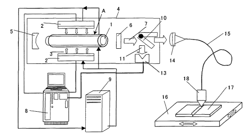
As one embodiment of the present claimed invention,
Fig. 1 shows an arrangement of a solid laser unit whose
primary purpose is a laser welding processing and mainly
comprising an LD excited pulse type Nd:YAG laser unit body A
wherein a laser activated media is rod-type Nd:YAG crystal 1
and a mean output is in a 300 W class.
CA 02461754 2004-03-25
11
The Nd:YAG crystal 1 whose rod diameter is 5 mm and
whose length is 116 mm is excited by LD light 3 radiated
from an LD excited unit 2 equipped with 60 bars of 20 W/bar
LDs oscillating at a central wavelength of 808 nm, light of
1.06 Eun irradiated from the Nd:YAG crystal 1 is selectively
amplified between a total reflection mirror 5 and an output
bond mirror 6 whose reflection coefficient is 70 0, each of
the mirrors 5, 6 constituting a laser resonator 4 whose
resonator length is 400 mm, so as to be Nd:YAG laser light 7
and then the Nd:YAG laser light 7 is radiated from the
output bond mirror 6. In addition, electricity is conducted
to the LD excited unit 2 by a direct current stabilized
power supply 8 and the Nd:YAG crystal 1 and the LD excited
unit 2 are temperature-controlled directly or through
purified water supplied by a purified water cooling system 9
to keep a temperature of its peripheral portion constant in
order to maintain an Nd:YAG laser output stable.
A beam shutter 10 and a laser output measuring
instrument 13 of a thermoelectric conversion type are
arranged in a beam transmission pass between the output bond
mirror 6 and incident gathering optical system 14 and when
the beam shutter 10 is open, the Nd:YAG laser light 7 enters
the incident gathering optical system 14 and is focused into
an optical fiber for transmission 15 whose core diameter is
0,3 mm and whose length is 10 m. The laser light radiated
from the optical fiber for transmission 15 is formed or
focused by radiation gathering optical system 18 so as to be
in a beam shape appropriate for processing an object to be
CA 02461754 2004-03-25
12
processed 17 placed on a CNC table 16 and then a required
laser processing is conducted.
In accordance with the arrangement, calibration of a
laser output value is conducted with an aim of applying an
accurate laser output value to the laser processing prior to
the laser processing by the use of the Nd:YAG laser light 7.
For this purpose the solid laser unit of this embodiment is
provided with a control means 20 shown in Fig. 3. The
control means 20 comprises a memory portion 21 that stores a
previously specified rectangle pulse current value and a
pulse laser output value corresponding to each rectangle
pulse current value, a calculating portion 22 that linear-
predicts a pulse current value corresponding to a necessary
pulse laser output based on the rectangle pulse current
value and the pulse laser output value stored in the memory
portion 2l and an output portion 23 to conduct the pulse
current value linear-predicted by the calculating portion 22
to the laser diode. In this embodiment a necessary value
such as the pulse laser output value stored in the memory
portion 21 is calculated beforehand by the calculating
portion 22. The control means 20 consists of the memory
portion 21, the calculating portion 22 and the output
portion 23 can be easily set up by the use of an ordinary
micro computer comprising a CPU, a memory and interface and
it is a matter of course that the control means 20 may be
set up with a single purpose machine.
Next a process of calibration by the use of the above
control means 20 will be shown.
CA 02461754 2004-03-25
13
A number of sampling for calibrating the laser output
here is set five and an LD current It as a regulation pulse
current value to give a laser oscillating threshold is set
25 A. (Refer to Fig. 2)
(1) Close the beam shutter 10 and change the beam
transmission pass so that all of the laser output of the
Nd:YAG laser light 7 enters the thermoelectric conversion
type laser output measuring instrument 13.
(2) Conduct a laser oscillating operation in a first
sample LD current value I1 as the rectangle pulse current
value under a condition of a pulse width t and a pulse
repetition.frequency f, measure a mean laser output Pal by
the thermoelectric conversion type laser output measuring
instrument 13 and then the pulse laser output value P1 is
calculated by the calculating portion 22 from the following
expression 1~ and store it in the memory portion 21.
Pn=Pan/ (i ~ f) expression 1~
When 't=0.5 msec, f=200 Hz and I1= 30 A, Pal=20 W; which
leads P1=200 W. In addition, a measuring data of Pal is a
value 3 seconds after the LD current is commanded to carry.
(3) Increase the sample LD current value alone in
sequence of I2, I3, I9, I5 with the same pulse width and the
same pulse repetition frequency, calculate the pulse laser
output value P2, P3, P4, P5 in each sample LD current value
by the calculating portion 22, store it in the memory
portion 21, make the sample LD current value not over the LD
current It and halt the laser oscillating operation.
When I2=50 A, I3=70 A, I4=90 A and I5=110 A, P2=530 W,
CA 02461754 2004-03-25
14
P3=1260 W, P4=2050 W and P5=3160 W.
In addition, every measuring data of each mean laser
output value Pan (n=2~5) is a value 3 seconds after the
sample LD current is commanded to carry.
(4)~Make the following linear expression to predict a
laser diode conducting pulse current value Ic wherein an
arbitrary pulse laser output value Pp up to the measured
maximum pulse laser output value P5 is obtained based on
data of each of the sample LD current values and pulse laser
output values.
In case of PlGPp~P2:
Ic= ( ( I2-I1 ) / ( P2-P1 ) ) Pp+ ( P2I1-P1I2expression O-1
) / ( P2-Pl )
In case of P2GPpcP3:
Ic= ( ( I3-I2 ) / ( P3-P2 ) ) Pp+ ( P3I2-P2I3expression 2O-2
) / ( P3-P2 )
In case of P3<Pp'cP4:
Ic=( (I4-I3) / (P9-P3) ) Pp+(P~I3-P3I4) expression O-3
/ (P4-P3)
In case of P4 < Pp'c P5 :
Ic= ( ( I5-I4 ) / ( P5-P9 ) ) Pp+ ( P5I4-P4I5expression 2O-4
) / ( P5-P4 )
In case of 0<Pp~Pi:
Ic=( (I1-It) /P1) ~ Pp+It expression O
If the expression 2O -1 ~ the expression 2~-4 are expressed
with a general relational expression;
In case of Pn-1<PpcPn (n~2)
Ic= ( ( In-In-1 ) / ( Pn-Pn-1 ) ) ~ Pp+ ( PnIn-1-Pn-lIn) / ( Pn-Pn-1 )
expression 2O
After the pulse laser output value is calibrated, the
calculating portion 22 calculates the laser diode conducting
pulse current value corresponding to a desired pulse laser
CA 02461754 2004-03-25
output from the relational expressions 2~ and 3~, and
conducts electricity to the LD through the output portion 23.
A program for the above is stored in the memory portion 21
of the control means 20 and the computing portion 22 runs
5 the program as the need arises and stores the result in the
memory portion 21. Fig. 4 is a schematic flow chart.
As a result, in case a command value of the pulse
laser output value is 150 W, 28.75 A of the pulse LD current
'is conducted, wherein an actual pulse laser output value was
10 152 W and the laser output was obtained with absolute
precision of about 1.3 s. In addition, in case a command
value of the pulse laser output value is 2500 W, 98 A of the
pulse LD current is conducted, wherein an actual pulse laser
output value was 2485 W and the laser output was obtained
15 with absolute precision of about 0.6 0.
In case that the pulse laser output value of the laser
unit body A is calibrated, the control means 20 is provided
with a function of updating the pulse laser output value
with a newly obtained data as long as a rate of change of
the pulse laser output value obtained in each laser diode
conducting pulse current value compared to the pulse laser
output value in the same current value obtained in the
previous calibration is not over a specified rate of change.
In addition, in case that the pulse laser output value
of the laser unit body A is calibrated, the control means 20
is provided with a function of displaying a content of an
error with regarding as an error of the laser unit body A
and ceasing calibration of the laser unit body A without
CA 02461754 2004-03-25
16
updating the pulse laser output value with a newly obtained
data when a rate of change of the pulse laser output value
obtained in each laser diode conducting pulse current value
compared to the pulse laser output value in the same current
value obtained in the previous calibration is larger than a
specified rate of change.
Above-described is one embodiment of the present
claimed invention, however, concrete arrangement of each
component is not limited to the above-described embodiment
and there may be various modifications without departing
from the spirit of the invention.
As mentioned above, since this arrangement is to solve
a problem of instability of a processing resulting from
instability of a laser output by calibrating the laser unit
body A prior to use of the solid laser unit, it is possible
to adopt this arrangement to a laser process unit.
In addition, a laser process unit will be further
improved in reliability by adopting the following
arrangement.
As another embodiment of the present claimed invention,
Fig. 5 shows an arrangement of a laser process unit whose
primary purpose is a laser welding processing and mainly
comprising an LD excited pulse type Nd:YAG laser unit AA
wherein a laser activated media is a rod-type Nd:YAG crystal
101 and a mean output is in a 300 W class.
An arrangement of the laser resonator and the beam
transmission system is the same as that of a conventional
example. The biggest difference between the conventional
CA 02461754 2004-03-25
17
example and this embodiment is that a monitor light output
measuring instrument 111 is changed to a PIN type Si photo
diode and monitor laser light 110 is made with a reflection
coefficient of a beam splitter 109 to radiated laser light
set about 1 0.
In monitoring an output of the Nd:YAG laser light 107,
the pulse laser light output that can be radiated from the
LD excited pulse type Nd:YAG laser unit AA can be monitored
during all of the laser radiating period if the PIN type Si
photo diode is used as a detector. In case of a laser
processing as shown in Fig. 6, however, since a processing
is generally conducted by the use of pulse laser light
consisting of various laser output values depending on a
portion to be processed, full-time monitoring has to be
conducted with a monitor reference value set in conjunction
with the pulse laser light. Under such circumstances, in
case of the processing condition No. 1 shown in Fig. 6
wherein pulse laser light having 0.5 msec of a pulse width
is driven at 100 Hz of a repetitive frequency, a monitor
sampling interval is required at least O.OS msec, and if
monitoring is conducted during 2.5 sec as all of a duration
while laser is radiated, approximate 5 X 10⁴ times of
comparison computing processes are required, which requires
a control unit comprising a computing unit whose processing
speed is high and a large volumetric memory, resulting in
high price of the laser unit.
In this embodiment of the present claimed invention, a
monitor period can be set to limit to a specific short
CA 02461754 2004-03-25
18
period as a simple method and only the maximum value during
the period is set as an object to be monitored.
Between a laser light radiating portion of the laser
unit AA and incident gathering optical system 113 as an
incident light guiding portion of an optical fiber for
transmission 114 as laser light transmission system into
which laser light radiated from the laser light radiating
portion, radiated laser light output reflecting off the beam
splitter 109 that separates part of laser light is set as
the monitor laser light 110 introduced into a monitor light
output measuring instrument 111 as a measuring instrument, a
laser output value of monitor laser light 110 incoming into
a high speed photo sensor directly or through a diffuse
reflection board is measured by the monitor light output
measuring instrument 111 and laser output value introduced
into the optical fiber for transmission 114 is presumptive
measured based on a reflection coefficient of radiated laser
light in the beam splitter 109.
As a concrete arrangement of the laser process unit is
shown in Fig. 7, the laser process unit comprises a maximum
value judge means 120 that obtains an actual maximum laser
output value as the maximum value of the laser light output
value measured during the specific monitor period while
laser light is radiated, an error judge means 121 that
compares the maximum value with the specific laser output
value as a monitor level after an elapsed time of a
predetermined specific monitor period and judges whether the
maximum value is within a specific range or not and a
CA 02461754 2004-03-25
19
trouble shooting means 122 that displays an alarm content
and simultaneously halts an operation of the laser process
unit when the error judge means 121 judges the maximum value
out of the specific range.
At least a part of the monitor light output measuring
instrument 111, the maximum value judge means 120, the error
judge means 121 and the trouble shooting means 122 can be
easily set up by an ordinary micro computer system
comprising a CPU, a memory and interface.
Fig. 8 is a flow chart showing a general description
of a program stored in the memory so as to be run by the CPU
and Fig. 6 shows a concrete monitor period while the laser
light is radiated. Explanation will be given with reference
to Fig. 6 and Fig. 8. The monitor light output measuring
instrument 111 starts sampling so as to monitor a monitor
laser light output as soon as laser light is radiated (S1,
S2) and terminates monitoring 100 msec (S5) after starting
sampling. The maximum laser output value is obtained (S3,
S4) during 100 cosec as a representative value during
monitoring at a normal time. This is because the maximum
value is the biggest in SlN value. The step S3, S4 may be
substituted by a peak hold circuit with ease. In the above
step to set the monitor laser light output at the normal
time as a monitoring reference, a reference maximum laser
output value is obtained while the laser unit is operated
under the same condition as that of an actual processing. In
addition, as a monitor reference range, each value of ~ 3% to
the reference maximum laser output value is set as an upper
CA 02461754 2004-03-25
limit specific laser output value and a lower limit specific
laser output value in consideration of a change (generally
0.5o/°C) of sensor sensitivity for ambient environment and
an allowable range in quality of a laser processing.
5 During the actual processing, the same step (Sl~SS) to
obtain the actual maximum laser output value as that of the
above-mentioned step to obtain the reference maximum laser
output value is conducted and in addition to this step, a
comparative step (S6) to compare the actual maximum laser
10 output value with the upper limit specific laser output
value and the lower limit specific laser output value built
on the monitor reference range is conducted. In case that
the actual maximum laser output value is out of a range from
the lower limit specific laser output value to the upper
15 limit specific laser output value, "Laser Output Error" is
displayed on an indicator of the laser process unit as alarm
just after termination of a monitor period as soon as a
trouble shooting process such as ceasing an operation of the
laser unit AA and the process unit is conducted (S7).
20 In accordance with the arrangement of this embodiment,
it is possible to monitor a laser output with high precision
with a simple arrangement such that the maximum value of the
laser output is always obtained during monitoring and a
comparison is made between a monitor reference value and the
latest maximum value as soon as the monitor period
terminates.
In addition, it is possible to halt operation of the
laser process unit immediately after an error happens
CA 02461754 2004-03-25
21
because an error laser output can be monitored during a
laser processing with a short input impulse at a low pulse
frequency that used to be impossible with a conventional art.
Concrete arrangement of each part is not limited to
the above-described embodiment.
For example, in the above other arrangement, the
monitor period for a monitor laser output is the period of
100 msec just after radiation of the laser light, however,
it may be an arbitrary period, which will produce the same
effect as far as the monitor period is within a period while
the laser light is radiated.
In addition, the monitor period in this embodiment is
a period of 100 cosec just after the laser light is radiated,
however, multiple of monitor periods may be provided as far
as the periods are within a period while the laser light is
radiated, which makes it possible to motitor a laser output
with higher accuracy.
Further, a photo diode having a few nsec of a response
speed is used in the above-mentioned embodiment. Since a
pulse width of laser light generally applied to a laser
processing is over 100 sec; 10 sec of a response speed of
the detector can be expected to produce a satisfactory
effect and function.
In addition, permeated laser light from a reflection
mirror that changes a transmission pass of radiated laser
light or permeated laser light from a total reflection
mirror, wherein each of the reflection mirror and the total
reflection mirror constitutes a laser resonator, may be set
CA 02461754 2004-03-25
22
as the monitor light of the above-mentioned measuring
instrument, a laser output value of the monitor light
incoming into a high speed photo sensor directly or through
a diffuse reflection board may be measured by the measuring
instrument and the permeated laser light may be introduced
into a laser light transmission system based on a ratio of
the permeated laser light to the radiated laser light.
Each of the above-mentioned embodiments may be
embodied by itself or both of the embodiments may be
embodied in combination.
Other arrangement may be variously modified without
departing from a~spirit of the present claimed invention.
POSSIHTF APPLICATIONS IN INDUSTRY
As mentioned above, in accordance with the pulse
oscillating type solid laser unit of the present claimed
invention, it is possible to radiate a pulse laser output
value with absolute precision of not greater than 2o in a
stable manner. For a laser welding processing by the use of
the Laser process unit in accordance with the above
embodiment, a welding defect such as a blow hole decreases
and a variation of a welding depth reduces, thereby to
improve a welding quality drastically.
In addition, in accordance with the laser process unit
of the present claimed invention, since processing defect
such as accuracy defect or strength defect originating in
excess or deficiency of laser output decreases drastically,
a yield ratio of a processing improves and a processing cost
CA 02461754 2004-03-25
23
is lowered. Further, processing material resources can be
economized and a running cost can be reduced, thereby to
provide a more global environment friendly laser process
unit.