Note: Descriptions are shown in the official language in which they were submitted.
CA 02462168 2004-03-26
ELECTRODE MATERIAL FOR LITHIUM SECONDARY BATTERY,
ELECTRODE STRUCTURE COMPRISING THE ELECTRODE MATERIAL
AND SECONDARY BATTERY COMPRISING THE ELECTRODE
STRUCTURE
BACKGROUND OF THE INVENTION
Field of the Invention
The present invention relates to an electrode
material for a lithium secondary battery that
comprises a powder of particles comprising silicon as
a major component, an electrode structure comprising
the electrode material and a secondary battery
comprising the electrode structure.
Related Background Art
Recently, it has been said that because the
amount of C02 gas contained in the air is increasing,
global warming may be occurring due to the greenhouse
effect. Thermal power plants use fossil fuels to
convert a thermal energy into an electric energy,
however they exhaust a large amount of C02 gas,
thereby making it difficult to newly construct
thermal power plants. Accordingly, for effective use
of an electric power generated in thermal power
plants, the so-called load leveling approach has been
proposed wherein an electric power generated at night,
which is an excess power, may be stored in a
household secondary battery or the like, whereby the
CA 02462168 2004-03-26
- 2 -
stored electric power can be used during the daytime
when electric power consumption increases.
Ln additian, the development of a high energy-
density secondary battery has been demanded for
electric vehicles that do not exhaust air pollutants
such as COx, NOX, and hydrocarbons. Further, the
development of compact, lightweight, high performance
secondary batteries is urgently demanded for
applications in portable electrical equipment such as
notebook personal computers, video cameras, digital
cameras, mobile phones, PDAs (Personal Digital
Assistant) or the like.
As such a lightweight, compact secondary
battery, a rocking chair type battery referred to as
"lithium ion battery" which, during a charging
reaction, uses a lithium intercalation compound as a
positive electrode substance for allowing lithium
ions to be deintercalated from between layers thereof
and uses a carbonaceous material represented by
graphite as a negative electrode substance for
allowing lithium ions to be intercalated between
planar layers of a 6-membered network-structure
formed of carbon atoms have been developed and partly
put into practical use.
However, with this "lithium ion battery",
because the negative electrode formed of a
carbonaceous material can theoretically intercalate
CA 02462168 2004-03-26
- 3 -
only a maximum of 1/6 of a lithium atom per one
carbon atom, a high energy-density secondary battery
comparable with a lithium primary battery when using
metallic lithium as a negative electrode material has
not been realized.
If an amount of lithium more than the
theoretical amount is tried to be intercalated in a
negative electrode comprising carbon of a "lithium
ion battery" during charging or charging is performed
under a high current density condition, there is a
possibility that lithium metal may grow in a dendrite
shape on the carbon negative electrode surface,
resulting in an internal short-circuit between the
negative and the positive electrodes due to repeated
charge/discharge cycles, so that any "lithium ion
battery" which has a capacity more than the
theoretical capacity of a graphite negative electrode
has not provided a sufficient cycle life.
On the other hand, a high-capacity lithium
secondary battery that uses metal lithium for a
negative electrode has been drawing attention but not
put in practical use yet.
This is because the charge/discharge cycle life
is very short. This short charge/dJ_scharge cycle
life is considered to be ascribed to the fact that
metal lithium reacts with impurities such as water or
organic solvents contained in the electrolyte to form
CA 02462168 2004-03-26
- 4 -
an insulating film or that the surface of a metallic
lithium foil is not flat and has a portion at which
an electric field is concentrated, whereby repeated
charging/discharging causes lithium to grow in a
dendrite shape, resulting in an internal short-
circuit between the negative and positive electrodes,
thereby leading to the end of the battery life.
In order to suppress the progress of the
reaction in which metal lithium reacts with water or
organic solvents contained in the electrolyte, which
is a problem peculiar to the secondary battery using
a metal lithium negative electrode, a method which
uses a lithium alloy containing lithium, aluminum and
the like as a negative electrode has been proposed.
However, this method is not currently in wide
practical use because the lithium alloy is too hard
to wind in a spiral form, and therefore a spiral-
wound type cylindrical battery cannot be made,
because the cycle life is not sufficiently long, and
because an energy density comparable to that of a
battery using metal lithium for a negative electrode
cannot sufficiently be obtained.
In order to resolve the above--mentioned
problems, heretofor, U.S. Patent Nos. 6,051,340,
5, 795, 679, and 6, 432, 585, Japanese :Patent Application
Laid-Open Nos. 11-283627 and 2000-311681 and
International Publication WO 00/17949 have proposed a
a CA 02462168 2004-03-26
- 5 -
secondary battery that uses a negative electrode for
a lithium secondary battery comprised of elemental
tin or silicon.
U.S. Patent No. 6,051,340 has proposed a
lithium secondary battery that uses a negative
electrode comprising an electrode layer formed of a
metal that is alloyable with lithium such as silicon
or tin and a metal that is not alloyable with lithium
on a current collector of a metal material that is
not alloyable with lithium.
U.S. Patent No. 5,795,679 proposes a lithium
secondary battery using a negative electrode formed
of a powder of an alloy of an element such as nickel
or copper with an element such as tin. U.S. Patent
No. 6,432,585 proposes a lithium secondary battery
that uses a negative electrode with an electrode
material layer containing 35% or more by weight of
particles comprised of silicon or tin with a average
particle diameter of 0.5 to 60 ~m and having a void
ratio of 0.10 to 0.86 and a density of 1.00 to 6.56
g / cm3 .
Japanese Patent Application Laid-Open No. 11-
283627 proposes a lithium secondary battery that uses
a negative electrode, comprising silicon or tin having
an amorphous phase; Japanese Patent Application Laid-
Open No. 2000-311681 proposes a lithium secondary
battery that uses a negative electrode comprising
CA 02462168 2004-03-26
- 6 -
amorphous tin-transition metal alloy particles with a
non-stoichiometric composition; and International
Publication WO 00/17949 proposes a lithium secondary
battery using a negative electrode comprising
amorphous silicon-transition metal alloy particles
with a non-stoichiometric composition.
However, in the lithium secondary batteries
according to the above-mentioned proposals, the
efficiency of the electricity amount involved in
lithium release relative to the electricity amount
involved in a first lithium insertion does not reach
the same level of performance as a graphite negative
electrode, so that further improvement in the
efficiency have been expected. In addition, since
the resistances of the electrodes of the lithium
secondary batteries of the above proposals are higher
than that of a graphite electrode, lowering in
resistance has been desired.
Japanese Patent Application Laid-Open No. 2000-
215887 proposes a high-capacity, high
charging/discharging efficiency lithium secondary
battery in which a carbon layer is formed on the
surface of particles of a metal or semi-metal which
is alloyable with lithium, in particular silicon
particles, through chemical vapor disposition using
thermal decomposition of benzene or the like to
improve electrical conductivity, thereby suppressing
CA 02462168 2004-03-26
-
volume expansion when alloying with lithium to
prevent breakage of an electrode.
However, with this lithium secondary battery,
while the theoretical charge capacity calculated for
Li4,4Si as a silicon/lithium compound is 4200 mAh/g,
an electrode performance allowing lithium
insertion/release of an electricity amount exceeding
1000 mAh/g has not been attained, so that development
of a high-capacity, long life negative electrode has
been desired.
SUMMARY OF THE INVENTION
The present invention has been accomplished in
view of the aforementioned problems, and it is an
object of the present invention to provide an
electrode material for a lithium secondary battery in
which capacity drop due to repeated
charging/discharging is small, and charge/discharge
cycle life is improved, an electrode structure
comprising the electrode material, and a secondary
battery comprising the electrode structure.
A first aspect of the present invention is an
electrode material for a lithium secondary battery
comprising alloy particles comprising silicon as a
major component and having an average particle
diameter of 0.02 ~;m to 5 ~,m, wherein the sire of a
crystallite of the alloy is not less than 2 nm but no
CA 02462168 2004-03-26
more than 500 nm and an intermetallic compound
containing at least tin is dispersed in a silicon
phase (First Invention).
A second aspect of the present invention is an
electrode material for a lithium secondary battery
comprising alloy particles comprising silicon as a
major component and having an average particle
diameter of 0.02 ~.un to 5 ~.un, wherein the size of a
crystallite of the alloy is not less than 2 nm but no
more than 500 nm and an at least one intermetallic
compound containing at least one. element selected
from the group consisting o.f aluminum, zinc, indium,
antimony, bismuth and lead is dispersed in a silicon
phase.
BRIEF DESCRIPTION OF THE DRAWINGS
FIG. 1 is a schematic sectional view of a
particle of an electrode material constituting the
electrode material structure according to the present
invention;
FIGS. 2A and 2B are conceptual views
schematically illustrating sections of an electrode
structure comprising the negative electrode material
of the lithium secondary battery according to an
embodiment of the present invention;
FLG. 3 is a conceptual view schematically
illustrating a section of a secondary battery
CA 02462168 2004-03-26
- 9 -
(lithium secondary battery) of an embodiment of the
present invention;
FIG. 4 is a cross-sectional view of a single
layer, flat type (coin type) battery;
FIG. 5 is a cross-sectional view of a spiral-
wound type cylindrical battery;
FIG. 6 is a scanning electron microscope
photograph of the electrode material prepared in
Example 1 of the present invention;
FIG. 7 is a view illustrating an X-ray
diffraction profile of the electrode material
prepared in Example 1 of the present invention;
FIG. 8 is a view illustrating a selected-area
electron diffraction image of the electrode material
prepared in Example 1 of the present invention;
FIG. 9 is a transmission electron microscope
photograph of the electrode material prepared in
Example 1 of the present invention;
FIG. 10 is a transmission electron microscope
photograph of the electrode material prepared in
Reference Example l;
FIG. 11 is views illustrating the results of
elemental mapping by means of the energy dispersive
X-ray spectroscopy (EDXS) analysis of the electrode
material prepared in Example l of the present
invention;
FIG. 12 is views.illustrating the results of
_ , CA 02462168 2004-03-26
- 10 -
elemental mapping by means of EDXS analysis of the
electrode material prepared in Reference Example 1~
and
FIG. 13 is a graphical representation showing
the results of release/insertion cycle tests of the
electrodes prepared in Examples 1 to 4 of the present
invention and Reference Examples 1 to 4.
DESCRIPTION OF THE PREFERRED EMBODIMENTS
Hereinafter, embodiments of the present
invention will be explained with reference to the
drawings.
The present inventors have previously found
that by adding tin or copper to silicon and using a
fine powder wherein the average particle diameter of
alloy particles comprising 50a or more by weight of
silicon element is not less than 0.1 Eun but no more
than 2.5 E.~m, a high-capacity lithium secondary
battery can be manufactured.
The present inventors have newly found that
with an electrode material in which an intermetallic
compound comprising tin or at least one intermetallic
compound comprising at least one el~ament selected
from the group consisting of aluminum, zinc, indium,
antimony, bismuth and lead is dispersed in a silicon
phase having a crystallite size of not less than 2 nm
and not more than 500 izm, the capacity drop due to
_ , , CA 02462168 2004-03-26
- 11 -
repeated charging/discharging can further be reduced
and the chargeldischarge cycle life can be improved,
to accomplish the present invention.
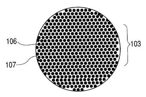
FIG. 1 is a schematic sectional view of a
particle of an electrode material that constitutes an
electrode structure according to the present
invention, in which reference numeral 103 denotes a
particle of the electrode material (active material)
comprising silicon as a major component according to
the present invention. The average particle diameter
of this electrode material particle 103 is 0.02 ~m to
5 ~.m.. Further, this electrode material particle 103
is comprised of a silicon phase 106 and an
intermetallic compound 107 which contains tin or an
element selected from the group consisting of
aluminum, zinc, indium, antimony, bismuth and lead.
That is, the electrode material 103 of the
present invention is characterized in that an
intermetallic compound 107 comprising tin or an
intermetallic compound 107 comprising an element
selected from the group consisting of aluminum, zinc,
indium, antimony, bismuth and lead is disperses in a
silicon phase having a crystallite size of 2 nm or
more and 500 nrn or less. Here, in addition to the
intermetallic compound 107, tin or the element
selected from the group, consisting of aluminum, zinc,
indium, antimony, bismuth and lead may also be
CA 02462168 2004-03-26
- 12 _
present in an elemental metal state.
The state "intermetallic compound 107 is
dispersed in silicon phase 106" referred to herein is
not intended to mean that the powder particle is
formed in a state of segregation in which the silicon
phase 106 and a phase of the intermetallic compound
107 are separated from each other but is intended to
mean the state such that the major component of the
powder particle is silicon arid the intermetallic
compound 107 is present as a mixture therein.
Further, such a state can be observed by means of
transmission electron microscope or selected-area
electron diffraction.
Elements that can form an intermetallic
compound with tin are preferably copper, nickel,
cobalt, iron, manganese, vanadium, molybdenum,
niobium, tantalum, titanium, zircon, yttrium,
lanthanum, selenium, magnesium and silver. Of those,
copper, nickel and cobalt are more preferable. With
tin these form intermetallic compounds such as
Cu41Sn11, CuloSn3, Cu5Sn4, CuSSn, Cu3Sn, Ni3Sn4, Ni3Sn2,
Ni3Sn, Co3Sn2, CoSn2, GoSn, Fe5Sn3, Fe3Sn2, FeSn2, FeSn,
Mn3Sn, Mn2Sn, MnSn2, Sn3V2, SnV3, Mo3Sn, Mo2Sn3, MoSn2,
NbSn2, Nb6Sn5, Nb3Sn, SnTa3, Sn3Ta2, SnTiz, SnTi3, Sn3Ti5,
Sn5Ti6, SnZr4, Sn2Zr, Sn3Zr5, Sn2Y, Sn3Y, Sn3Y5, Sn4Y5.
SnloYIl, LaSn, LaSn3, La2Sn3, La3Sn, La3Sn5, La5Sn3,
La5Sn4, LallSnlo. CesSn, Ce5Sn3, CeSSn~,, CeizSnlo, Ce3Sn5,
CA 02462168 2004-03-26
- 13 -
Ce3Sn?, Ce2Sn5, CeSn3, Mg2Sn, Ag3Sn, and Ag~Sn.
Meanwhile, when silicon is used as an electrode
material, because the volume change at the time of
the reaction of insertion into silicon and release
from silicon of lithium involved in
charging/discharging is large, the crystalline
structure of silicon will rupture to convert the
particles into a fine powder, so that the
charging/discharging becomes unable to be performed.
Therefore, the present inventors have
previously found that by using amorphized silicon, or
a fine powder of a silicon alloy, the cycle life can
be improved, and further found that by dispersing in
a silicon phase an intermetallic compound comprising
tin, or an intermetallic compound comprising an
element selected from the group consisting of
aluminum, zinc, indium, antimony, bismuth and lead,
lithium can be uniformly inserted into the silicon
phase, thereby improving the cycle life.
Explaining this by taking a case of tin as one
example, the electric potential E1 (Li/Li+) of the
electrochemical oxidation/reduction reaction (1) of
lithium to tin is nobler than the electric potential
E2 (Li/Li+) of the oxidation/reduction reaction (2)
of lithium to silicon.
( 1 ) Sn + xLi --~ LiXSn E1 (Li/Li+)
(2) Si + xLi -3 LiXSi E2 (Li/Li+)
CA 02462168 2004-03-26
E1 (Li/Li+) > E2 (Li/Li+)
Here, since the lithium insertion reaction
involved in charging begins from the nobler potential
side, it is considered that the lithium insertion
begins with tin followed by silicon. Therefore, it
is considered that by uniformly dispersing tin in the
silicon phase, the lithium insertion reaction into
the silicon phase occurs uniformly, so that uniform
incorporation of lithium into the silicon phase makes
it possible to suppress the breakage of the
crystalline structure of silicon.
Meanwhile, industrially convenient means for
preparing an alloyed powder of silicon and tin
include the so-called gas atomization method that
performs alloying by atomizing a mixed and molten
material, or the water atomization :method. However,
because there is a large difference in melting paint
such that while silicon has a melting point of 1412°C,
tin has a melting point of 231.9°C, the alloy powder
is liable to be formed in a state such that a silicon
phase and a tin phase are separate from each other.
As means to suppress this, as shown in First
Invention, it is effective to use an intermetallic
compound comprising tin.
Specifically, when preparing the alloy, it is
effective to adopt a method in which at least one
element that forms an intermetallic compound with tin
CA 02462168 2004-03-26
- 15 -
selected from the group consisting of copper, nickel,
cobalt, iron, manganese, vanadium, molybdenum,
niobium, tantalum, titanium, zirconium, yttrium,
lanthanum, selenium, magnesium and silver is added,
along with tin.
Here, because these intermetallic compounds
have a higher melting point than that of tin, the
difference in melting point from silicon can be made
smaller, so that the tin phase and the alloy phase
can uniformly be dispersed. Forming the
intermetallic compound is also effective in
suppressing the volume change when incorporating
lithium.
Further, the elements of aluminum, zinc, indium,
antimony, bismuth and lead can also electrochemically
insert and release Li, and their oxidation/reduction
reaction potentials for Li are nobler than that of
silicon as is the case with tin. Further, the
melting points of these elements, i.e., aluminum
(660°C) , zinc (419.5°C) , indium (156.4°C) , antimony
(630.5°C), bismuth (271°C) and lead (327.4°C), are
lower than that of silicon. Thus, as shown in Second
Invention, by forming an intermetallic compound
containing at least one of these elements to reduce
the difference in melting point from silicon, uniform
dispersion can be achieved.
These intermetallic compounds include AlCu,
CA 02462168 2004-03-26
- 16 -
AlCu2, AlCu3, Al2Cu, A12Cu3, Al2Cu~, Al3Cu~, A14Cu5, CuZn,
CuZn3, CuZn4, Cu5Zn8, Cu2In, Cu4In, Cu~In3, Cu11In9,
Cu2Sb, Cu3Sb, Cu4Sb, CuSSb, CuloSb3, BiNi, Bi3Ni, Bi3Pb~
and Pb3Zr5.
The content of silicon in the alloy is
preferably 50% or more by weight in order to exhibit
the performance of a high chargeable amount as a
lithium secondary battery negative electrode material.
Further, the average particle diameter of the silicon
alloy primary particles of the present invention is,
as a lithium secondary battery negative electrode
material, preferably within the range of 0.02 to 5.0
Ettn, and more preferably within the range of 0.05 to
1.0 ~.m so that the electrochemical lithium
insertion/release reaction occurs rapidly and
uniformly. The term '°average particle diameter" used
herein is intended to mean the average primary
particle diameter (average particle diameter in an
non-agglomerated state).
Here, if the above average particle diameter is
too small, handling becomes less easy, the area of
contact between particles when forming an electrode
increases, thereby increasing the contact resistance.
However, in the case of adopting the average particle
diameter of the primary particles as mentioned above,
making the particles larger by aggregating the
primary particles leads to easier handling and
CA 02462168 2004-03-26
lowering in the resistance.
In order to obtain a battery with a long life
cycle, it is preferable that the crystalline
structure of a ground fine powder contains an
amorphous phase. Further, when a fine powder of a
negative electrode material prepared by the method of
producing a lithium secondary battery negative
electrode material according to the present invention
contains an amorphous phase, the volume expansion
when alloying with lithium can be reduced.
Further, when the ratio of the amorphous phase
becomes larger, the full width at half maximum of a
peak of an X-ray diffraction chart, which is sharp
for a crystalline material, widens, becoming broader.
Incidentally, the full width at half maximum of a
main peak of an X-ray diffraction chart of
diffraction intensity for 28 is preferably 0.1° or
more, and more preferably 0.2° or more.
The size of the crystallite of the negative
electrode material powder (powder of particles
comprising silicon as a major component) prepared
according to the present invention, in particular in
a state in which the electrode structure has not been
subjected to charging/discharging yet (i.e., in an
unused state) is preferably controlled to be not less
than 2 nm but no more than 500 nm, more preferably
controlled to be not less than 2 nm but no more than
CA 02462168 2004-03-26
- 18 -
50 nm, and most preferably controlled to be not less
than 2 nm but no more than 30 nm. By using such a
fine crystalline powder, the electrochemical reaction
during eharging/discharging can be performed more
smoothly, whereby the charging capacity can be
improved. Further, the distortion caused by the
insertion/release of lithium during
charging/discharging can be minimized to increase the
cycle life.
In the present invention, the crystallite size
of the particles is determined using the following
Scherrer equation on the basis of the full width at
half maximum of a peak and the diffraction angle of
an X-ray diffraction curve using CuKa as an radiation
source.
Lc = 0. 94~,/ ((3cos~) (Scherrer Equation)
Lc: crystallite size
~,: wavelength of X-ray beam
(3: full width at half maximum of peak (radian)
B: Bragg angle of diffracted rays
Meanwhile, methods for preparing the electrode
material according to the present invention includes
the following:
(A) A method wherein silicon, tin or aluminum, zinc,
indium, antimony, bismuth, lead, a transition metal,
or the like are mixed and molten and then subjected
to atomization to form an alloy (e.g., gas
CA 02462168 2004-03-26 .
- 19 -
atomization or water atomization method);
(B) A method wherein a silicon alloy ingot prepared
by mixing and melting silicon, tin or aluminum, zinc,
indium, antimony, bismuth, lead, a transition metal
or the like is ground;
(C) A method wherein silicon powder, tin powder or
a powder of aluminum, zinc, indium, antimony, bismuth,
lead, a transition metal, or the like are ground and
mixed in an inert gas atmosphere to form an alloy
(mechanical alloying); and
(D) A method wherein an alloy is formed from a gas
phase by means of plasma, electron beam, laser or
induction heating using a volatile chloride (or other
halides), oxide or the likee
In addition, by mechanically grinding these
alloyed powders, it becomes possible to uniformly
disperse in a silicon phase an intermetallic compound
comprising tin, or at least one intermetallic
compound comprising at least one element selected
from the group consisting of aluminum, zinc, indium,
antimony, bismuth and. lead:
Here, as the mechanical grinding apparatus,
there are preferably used a ball mill such as a
planetary ball mill, a vibrating ball mill, a conical
mill and a tube mills a media mill such as an
attrition mill, a sand grinder, an annular mill and a
tower mill. The material of the balls as the above
_ , , CA 02462168 2004-03-26
- 20 -
grinding media is preferably zirconia, stainless
steel or steel.
Incidentally, the grinding may be performed in
either of a wet process or dry process. In wet
grinding, the alloy powder is ground in a solvent or
ground after a certain amount of solvent is added.
The solvent used in wet grinding may be water or an
organic solvent such as alcohol, hexane, etc.
Examples of alcohol include methyl alcohol, ethyl
alcohol, 1-propyl alcohol, 2-propyl alcohol,
isopropyl alcohol, 1-butyl alcohol, 2-butyl alcohol
and the like.
FIGS. 2A and 2B illustrate schematically
sections of an electrode structure according to the
present invention. In FIG. 2A, reference numeral 102
denotes an electrode structure: This electrode
structure 102 is constituted of an electrode material
layer 101 and a current collector 100. This
electrode material layer 101 is constituted of, as
illustrated in FIG. 2B, particles (active material)
103 comprising silicon as a major component, a
conductive auxiliary material 104 and a binder 105.
Incidentally, it should be noted that although in
FIGS. 2A and 2B the electrode material layer 101 is
provided only on ane surface of the current collector
100,.an electrode material layer may be formed on
both sides of the current collector 100;respectively,
CA 02462168 2004-03-26
- 21 -
depending on the battery configuration.
Here, the content of the conductive auxiliary
material 104 is preferably not less than 5% by weight
but no more than 40% by weight, and more preferably
not less than 10% by weight but no more than 30% by
weight. The content of the binder 105 is preferably
not less than 2a by weight but no more than 20% by
weight, and more preferably not less than 5% by
weight but no more than 15% by weight. The content
of the particles (powder) 103 comprising silicon as a
major component in the electrode material 101 is
preferably within the range of 40% by weight to 930
by weight.
The conductive auxiliary material 104 used
includes carbonaceous materials such as amorphous
carbons such as acetylene black and ketjenblack and
graphite structure carbon, nickel, copper, silver,
titanium, platinum, aluminium, cobalt, iron, chrome
and the like, and especially graphite is preferable.
The shape of the conductive auxiliary material may
preferably be a shape selected from a spherical shape,
a flake shape, a filament shape, a fiber shape, a
spike shape, a needle shape, and the like. In
addition, by employing two or more different shapes
of powders, the packing density when forming the
electrode material layer can be increased, thereby
reducing the impedance of the electrode structure 102.
CA 02462168 2004-03-26
- 22 -
The material for the binder 105 may include a
water-soluble polymer such as polyvinyl alcohol,
water-soluble ethylene-vinyl alcohol copolymer,
polyvinyl butyral, polyethylene glycol, sodium
carboxymethyl cellulose and hydroxyethyl cellulose a
fluororesin such as polyvinylidene fluoride and
vinylidene fluoride-hexafluoropropylene copolymer; a
polyolefin such as polyethylene and polypropylene;
styrene-butadiene rubber, polyamide-imide, polyimide,
and polyamic acid (polyamide precursor). Of these,
when a combination of polyvinyl alcohol and sodium
carboxymethyl cellulose, polyamide-imide or polyamic
acid (polyamide precursor) is used, the strength of
the electrode increases, whereby an electrode with an
excellent charge/discharge cycle characteristic can
be manufactured.
In addition, because the current collector 100
has the role of efficiently supplying an electric
current to be consumed by the electrode reaction
during charging, or collecting an electric current
generated during discharging, in particular when
applying the electrode structure 102 to an negative
electrode of a secondary battery, it is desirable
that the current collector 100 is formed of a
material that has a high electric conductivity and is
inert to the battery reactions. Preferable materials
include at least one metallic material selected from
CA 02462168 2004-03-26
- 23 -
the group consisting of copper, nickel, iron,
stainless steel, titanium and platinum. A more
preferable material is copper that is inexpensive and
has a low electrical resistance.
Further, while the shape of the current
collector 100 is a plate shape, this "plate shape" is,
within the scope of practical use, not particularly
limited in thickness, and encompasses the so-called
"foil" shape having a thickness of about 100 Eun or
less. As the plate shape member, for example, a
meshy, spongy or fibrous member, punching metal, or
expanded metal can also be employed.
Now, a procedure for manufacturing the
electrode structure 102 will be explained.
First, the conductive auxiliary material 104
and the binder 105 are mixed with a silicon alloy
powder of the present invention, to which an
appropriate amount of a solvent for the binder 105 is
added, followed by kneading to prepare a paste. Then,
the prepared paste is applied to the current
collector 100 and dried to form the electrode
material layer 101, and pressing is then effected to
adjust the thickness and density of the electrode
material layer 101 thus forming the electrode
structure 102.
As the above-mentioned application method, a
coater coating method or a screen printing method can
CA 02462168 2004-03-26
- 24 -
be used. In addition, the above major component
along with the conductive auxiliary material 104 and
the binder 105, without addition of a solvent, or the
above negative electrode material along with the
conductive auxiliary material 104 alone, without
addition of the binder 105, may be subject to
pressure forming on the current collector to form the
electrode material layer 101.
Here, if the density of the electrode material
layer 101 is too large, the expansion at the time of
lithium insertion becomes greater, so that peeling
off of the electrode material layer 101 from the
current collector 100 occurs, and if the density of
the electrode material layer 101 is too small, the
resistance of the electrode becomes greater, so that
the lowering in charging/discharging efficiency and
the drop in voltage of the battery at the time of
discharging become greater. For these reasons, the
density of the electrode material layer 101 according
to the present invention is preferably within the
range of 0.8 to 2.0 g/cm3, and more preferably within
the range of 0.9 to 1.5 g/cm3.
Incidentally, an electrode structure 102 formed
only of the silicon alloy particles of the present
invention without using the conductive auxiliary
material 104 and the binder 105 can be made by
directly forming an electrode material layer I01 on
CA 02462168 2004-03-26
- 25 -
the current collector 200 using a method such as
sputtering, electron beam evaporation, cluster ion
beam deposition, or the like.
However, in this case, if the electrode
material layer 101 is thick, peeling off is liable to
occur at the interface with the current collector 200,
so that the above-mentioned direct formation is not
suitable for formation of a thick electrode structure
102. Incidentally, in order to prevent the above
peeling off, it is preferred that a metal layer or an
oxide layer or a nitride layer is provided in a
thickness of a manometer order on the current
collector 100 to form an unevenness in the surface of
the current collector 200, thereby improving the
adhesion at the interface. Examples of the oxide
layer and nitride layer preferably include an oxide
layer or nitride layer of silicon or a metal.
Meanwhile, the secondary battery according to
the present invention comprises a negative electrode
using the electrode structure as characterized above,
an electrolyte and a positive electrode and utilizes
an oxidation reaction of lithium and a reduction
reaction of lithium ions.
FIG. 3 is a view schematically showing a basic
structure of the lithium secondary battery according
to the present invention, in which reference numeral
201 denotes a negative electrode 'using an electrode
CA 02462168 2004-03-26
- 26 -
structure of the present invention, reference numeral
202 an ionic conductor, reference numeral 203 a
positive electrode, reference numeral 204 a negative
electrode terminal, reference numeral 205 a positive
electrode terminal and reference numeral 206 a
battery case (housingy.
Here, the above secondary battery is assembled
in such a way that the ionic conductor 202 is
sandwiched and stacked between the negative electrode
201 and the positive electrode 203 to form an
electrode group, then after this electrode group has
been inserted into the battery case in dry air or a
dry inert gas atmosphere in which the dew point is
sufficiently controlled, the electrodes 201, 203 are
contacted to the electrode terminals 204, 205,
respectively and the battery case is sealed.
Incidentally, when using a member having an
electrolyte held in a micro-porous plastic film as
the ionic conductor 202, the battery is assembled by
inserting a micro-porous plastic film between the
negative electrode 201 and the positive electrode 203
as a separator to prevent short-circuiting to form an
electrode group, then inserting the electrode group
into the battery case, connecting the electrodes 201,
203 to the electrode terminals 204, 205, respectively,
injecting the electrolyte and sealing the battery
case.
CA 02462168 2004-03-26
- 27 -
The lithium secondary battery that uses an
electrode structure comprising an electrode material
of the present invention as the negative electrode
has a high charging/discharging efficiency and
capacity and a high energy density owing to the
above-mentioned advantageous effects of the negative
electrode.
Herein, the positive electrode 203, which is
the counter electrode of the lithium secondary
battery using the electrode structure of the present
invention as the negative electrode, comprises a
positive electrode material that is at least a
lithium ion source and serves as a host material for
lithium ions, and preferably comprises a layer formed
of a positive electrode material that serves as a
host material for lithium ions and a current
collector. Further, it is preferable that the layer
formed of the positive electrode material comprises
the positive electrode material that serves as a host
material for lithium ions and a binder, and a
conductive auxiliary material as occasion demands.
As the positive electrode material that is a
lithium ion source and serves as a host material used
in the lithium secondary battery of the present
invention, there are preferably included lithium-
transition metal oxides, lithium-transition metal
sulfides, lithium-transition metal nitrides and
CA 02462168 2004-03-26
- 28 -
lithium-transition metal phosphates. The transition
metal for the transition metal oxides, transition
metal sulfides, transition metal nitrides or
transition metal phosphates includes, for example,
metal elements having a d-shell or f-shell, i.e., Sc,
Y, lanthanoids, actinoids, Ti, Zr, Hf, V, Nb, Ta, Cr,
MO, W, Mn, TC, Re, Fe, Ru, llS, CO, Rh, Ir, N7., Pb, Pt,
Cu, Ag, and Au, and in particular Co, Ni, Mn, Fe, Cr,
and Ti are preferably used.
Where the above positive electrode active
material is a powder, the positive electrode is made
by using a binder, or made by forming the positive
electrode active material layer on the current
collector by calcination or deposition. Further,
when the conductivity of the powder of the positive
electrode active material is low, it becomes
necessary to suitably mix a conductive auxiliary
material therewith as in the above-mentioned
formation of the active material layer for the
electrode structure. The conductive auxiliary
materials and binders that may be used are the same
as those mentioned above for the electrode structure
102 of the present invention.
The current collector material used for the
positive electrode is preferably a material that has
a high electrical conductivity and is inert to the
battery reaction, such as~aluminlum, titanium, nickel
CA 02462168 2004-03-26
- 29 -
and platinum. Specifically, nickel, stainless steel,
titanium and aluminium are preferable, of which
aluminium is mare preferable because it is
inexpensive and has a high electrical conductivity.
Further, while the shape of the current collector is
a plate shape, this '°plate shape" is, within the
scope of practical use, not particularly limited in
thickness, and encompasses the so-called "foil" shape
having a thickness of about 100 ~m or less. As the
plate shape member, for example, a meshy, spongy or
fibrous member, punching metal, or expanded metal can
also be employed
In addition, as the ionic conductor 202 of the
lithium secondary battery of the present invention,
lithium ion conductors such as a separator holding an
electrolyte solution (electrolyte solution prepared
by dissolving an electrolyte in a solvent), a solid
electrolyte, or a solidified electrolyte obtained by
gelling an electrolyte solution with a polymer gel, a
complex of a polymer gel and a solid electrolyte can
be used. Here, the conductivity of the ionic
conductor 202 at 25°C is preferably l x 10-3 S/cm or
more, and more preferably 5 x 10-~ S/cm or more.
As the electrolyte, there may be included salts
comprised of lithium ions (Li+) and Lewis acid ions
(BF4 , PF6-, AsF6-, C104 , CF3S03-, or BPh4' (Ph: phenyl
group)) and mixtures thereof. It is preferable that
CA 02462168 2004-03-26
- 30 -
the above salts have been previously subjected to
sufficient dehydration and deoxidation by heating
under a reduced pressure or the like.
As a solvent for the electrolyte, there may be
included, for example, acetonitrile, benzonitrile,
propylene carbonate, ethylene carbonate, dimethyl
carbonate, diethyl carbonate, ethylmethyi carbonate,
dimethyl formamide, tetrahydrofuran, nitrobenzene,
dichloroethane, diethoxyethane, 1,2-dimethoxyethane,
chlorobenzene, y-butyrolactone, dioxolane, sulfolane,
nitromethane, dimethyl sulfide, dimethyl sulfoxide,
methyl formats, 3-methyl-2-oxazolidinone, 2-
methyltetrahydrafulan, 3-propylsydnone, sulfur
dioxide, phosphoryl chloride, thionyl chloride,
sulfuryl chloride or a liquid mixture thereof.
Incidentally, it is preferable to either
dehydrate the above-mentioned solvent, for example,
with activated alumina, a molecular sieve, phosphorus
pentaoxide or calcium chloride, or depending on the
solvent, to distill the solvent in an inert gas
atmosphere in the presence of an alkaline metal for
elimination of impurities and dehydration.
In order to prevent leakage of the electrolyte
solution, it is preferable to use a solid electrolyte
or a solidified electrolyte. The solid electrolyte
may include a glass material such as an oxide
material comprising lithium, silicon, oxygen, and
CA 02462168 2004-03-26
- 32 -
phosphorus or sulfur elements, a polymer complex of
an organic polymer having an ether structure. The
solidified electrolyte is preferably obtained by
gelling the above electrolyte solution with a gelling
agent to solidify the electrolyte solution.
It is desirable to use as the gelling agent a
polymer that can absorb the solvent of the
electrolyte solution to swell, or a porous material
capable of absorbing a large amount of liquid, such
as silica gel. As the polymer, there may be used
polyethylene oxide, polyvinyl alcohol,
polyacrylonitrile, polymethylmethacrylate,
vinylidenefluoride-hexafluoropropylene copolymer, and
the like. Further, it is more preferred that the
polymers have a cross-linking structure.
The ionic conductor 202 constituting the
separator which plays the role of preventing short-
circuiting between the negative electrode 201 and the
positive electrode 203 in the secondary battery may
also have a role of retaining the electrolyte
solution and is required to have a large number of
fine pores through which lithium ions can pass and to
be insoluble and stable in the electrolyte solution.
Accordingly, as the material of the ionic
conductor 202 (separator), there are preferably used,
for example, a material of a micropore structure made
of glass, a polyolefin such as polypropylene or
CA 02462168 2004-03-26
- 32 -
polyethylene, a fluororesin, etc., or a nonwoven
fabric. Alternatively, a metal oxide film having
micropores or a resin film complexed with a metal
oxide may also be used.
Now, the shape and structure of the secondary
battery will be explained.
The specific shape of the secondary battery
according to the present invention may be, for
example, a flat shape, a cylindrical shape, a
rectangular parallelepiped shape, a sheet shape or
the like. The structure of the battery may be, for
example, a single layer type, a multiple layer type,
a spiral-wound type or the like. Of those, a spiral-
wound type cylindrical battery permits an enlarged
electrode surface area by rolling a separator that is
sandwiched between a negative electrode and a
positive electrode, thereby being capable of
supplying a large current at the time of
charging/discharging. Furthermore, batteries having
a rectangular parallelepiped shape or sheet shape
permit effective utilization of accommodation space
in appliances that will be configured by
accommodating a. plurality of batteries therein.
Now, description will be made in more detail of
the shape and structure of the battery with reference
to FIGS. 4 and 5. FTG. 4 is a sectional view of a
single layer type flat (i.e., coin type) battery and
CA 02462168 2004-03-26
- 33 -
FIG. 5 is a sectional view of a spiral-wound type
cylindrical battery. These lithium secondary
batteries generally comprise the same structure as
that illustrated in FIG. 3, a negative electrode, a
positive electrode, an electrolyte, an ionic
conductor, a battery housing and an output terminal.
In FIGS. 4 and 5, reference numerals 301, 403
denote negative electrodes, reference numerals 303,
406 positive electrodes, reference numerals 304, 408
negative electrode caps or negative electrode cans as
negative electrode terminals, reference numerals 305,
409 positive electrode caps or positive electrode
cans as positive electrode terminals, reference
numeral 302, 407 ionic conductors, reference numerals
306, 410 gaskets, reference numeral. 401 represents a
negative electrode current collector, reference
numeral 404 a positive electrode current collector,
reference numeral 411 an insulating plate, reference
numeral 412 a negative electrode lead, reference
numeral 413 a positive electrode lead, and reference
numeral 414 a safety valve.
In the flat secondary battery (coin typed shown
in FIG. 4, the positive electrode 303 that contains a
positive electrode material layer and the negative
electrode 301 that contains a negative electrode
material layer are stacked with an ionic conductor
302 which is formed by a separator that retains at
s CA 02462168 2004-03-26
- 34 -
least an electrolyte solution therein, wherein the
stack is accommodated from the positive electrode
side into the positive electrode can 305 used as a
positive terminal and the negative electrode is
covered with the negative electrode cap 304 used as a
negative electrode. A gasket 306 is provided in the
remaining portions of the positive electrode can.
In the spiral-wound type cylindrical secondary
battery shown in FIG. 5, the positive electrode 406
having a positive electrode (material) layer 405
formed on the positive electrode current collector
404 and the negative electrode 403 having the
negative electrode (material) layer 402 formed on the
negative electrode current collector 401 are provided
in opposition to each other via the ionic conductor
407 formed by a separator that retains at least an
electrolyte solution therein so as to form a stack of
a cylindrical structure rolled up multiple times.
The cylindrical stack is accommodated in the
negative electrode can 408 used as -the negative
electrode terminal. Furthermore, the positive
electrode cap 409 is dispased as the positive
electrode terminal on a side of an opening of the
negative electrode can 408 and a gasket 410 is
disposed in the remaining parts of the negative
electrode can. The cylindrical electrode stack is
isolated from the positive electrode cap side by the
CA 02462168 2004-03-26
- 35 -
insulating plate 411.
The positive electrode 406 is connected to the
positive electrode cap 409 by way of the positive
electrode lead 413. The negative electrode 403 is
connected to the negative electrode cap 408 by way of
the negative electrode lead 412. The safety valve
414 is disposed on the side of the positive electrode
cap to adjust the internal pressure of the battery.
As mentioned above, a layer comprising the above
negative electrode material fine powder of the
present invention is used as the active material
layer 402 of the negative electrode 403.
Next, an example of assembling procedures for
the battery shown in FIGS. 4 and 5 will be described.
(1) The ionic conductor 302, 407 as a separator is
sandwiched between the negative electrode 301, 403
and the formed positive electrode 303, 406, and
assembled into the positive electrode can 305 or the
negative electrode can 408.
(2) After injection of the electrolyte solution,
the negative electrode cap 304 or the positive
electrode cap 409 is assembled with the gasket 306,
410.
(3) The assembly obtained in (2) above is caulked.
The battery is completed in this way.
Incidentally, it is preferable that the above-
described preparation of the materials for the
CA 02462168 2004-03-26
- 36 -
lithium battery and assembly of the battery is
carried out in dry air from which moisture has been
removed sufficiently or in a dry inert gas.
Next, members comprising the secondary battery
will be described.
As the material of the gasket 306, 410, there
may be used, for example, a fluororesin, a polyolefin
resin, a polyamide resin, a polysulfone resin, or a
rubber material. The sealing of the battery may be
conducted by way of glass-sealing, sealing using an
adhesive, welding or soldering, besides the caulking
using the insulating packing shown in FIGS. 4 or 5.
As the material of the insulating plate 411 shown in
FIG. 4, organic resin materials and ceramics may be
used.
The battery housing is constituted of the
positive electrode can 305 or the negative electrode
can 408, and the negative electrode cap 304 or the
positive electrode cap 409. As the material of the
battery housing, stainless steel is preferably used.
Further, as other materials of the battery housing,
there are frequently used an aluminum alloy, a
titanium clad stainless steel, a copper clad
stainless steel or a nickel-plated steel.
The positive electrode can 305 illustrated in
FIG. 4 and the negative electrode can 408 illustrated
in FIG. 5 function as the battery housing (case) and
CA 02462168 2004-03-26
- 37 -
also as a terminal and is therefore preferably made
of stainless steel. However, where the positive
electrode 305 or the negative electrode 408 does not
function as both the battery housing (case) and the
terminal, in addition to stainless steel., a metal
such as zinc, a plastic such as polypropylene, a
composite material of a metal or glass fibers and a
plastic may be used.
As the safety valve 414 provided in the lithium
secondary battery in order to ensure safety when the
internal pressure in the battery is increased, for
example, rubber, a spring, a metal ball or a rupture
disk may be used.
(Examples)
In the following, the present invention will be
described in more detail with reference to examples.
(Preparation of Electrode Material)
First, examples for the preparation of a
negative electrode material will be explained.
(Example 1)
65% by weight of Si, 30% by weight of Sn and 5%
by weight of Cu were melted and mixed to make an
alloy, which was subjected to water atomization to
prepared a Si-Sn-Cu alloy powder having an average
particle diameter of 10 ~.un. Next, the prepared alloy
powder was ground with a bead mill (ball mill using
beads with comparatively small diameter as grinding
CA 02462168 2004-03-26
- 38 _
media) to obtain a Si-Sn-Cu alloy fine powder. This
grinding was performed using zircon.ia beads in
isopropyl alcohol.
Then, processing for 2 hours in a high-energy
planetary-type ball mill in an argon gas atmosphere
using balls made of silicon nitride provided an
electrode material of Si-Sn-Cu alloy fine powder.
(Example 2)
An electrode material of a Si-Zn-Cu alloy fine
powder was obtained following the same procedure as
Example 1 with the exception that a:n alloy with a
composition of 70o by weight of Si, 25o by weight of
Zn and 5o by weight of Cu was prepared by a gas
atomization process using nitrogen gas.
(Example 3)
An electrode material of a Si--Sn-Co alloy fine
powder was obtained following the same procedure as
Example 1 with the exception that an alloy with a
composition of 50% by weight of Si, 40o by weight of
Sn and 10o by weight of Co was prepared by a water
atomization process.
(Example 4y
An electrode material of a Si--Sn-Ni alloy fine
powder was obtained following the same procedure as
Example 1 with the exception that an alloy with a
composition of 85o by weight of Si, l0o by weight of
Sn and 5o by weight of Ni was prepared by a water
CA 02462168 2004-03-26
- 39 -
atomization process.
(Reference Example 1)
An electrode material of a Si--Sn-Cu alloy fine
powder was obtained following the same procedure as
Example 1 with the exception that the processing in a
high-energy planetary-type ball mill was not
performed.
(Reference Example 2)
An electrode material of a Si--Zn-Cu alloy fine
powder was obtained following the same procedure as
Example 2 with the exception that the processing in a
high-energy planetary-type hall mill was not
performed.
(Reference Example 3)
An electrode material of a Si-Sn-Co alloy fine
powder was obtained following the same procedure as
Example 3 with the exception that the processing in a
high-energy planetary-type ball mill was not
performed.
(Reference Example 4)
An electrode material of a Si-Sn-Ni alloy fine
powder was obtained following the same procedure as
Example 4 with the exception that the processing in a
high-energy planetary-type ball mill was not
performed.
Next, the results of analyzing the electrode
materials obtained in Examples 1 to 4 and Reference
CA 02462168 2004-03-26
- 40 -
Examples 1 to 4 will be explained.
The above Si alloy electrode materials were
analyzed from the viewpoint of factors that are
considered to affect the performance of a negative
electrode of a lithium secondary battery, such as
average particle diameter, crystallite size,
intermetallic compounds of Sn or Zn, and distribution
of elements in the alloy.
Here, the average particle diameter was
determined by a laser diffraction/scattering particle
size distribution analyzer, and further observed with
a scanning electron microscope (SEM). Further, the
crystallite size was calculated from the full width
at half maximum of an X-ray diffraction peak in
accordance with the Scherrer equation, and detection
of Sn or Zn intermetallic compounds was performed by
investigation using the selected-area electron
diffraction.
Further, the distribution of elements in the
alloy was investigated by TEM observation in terms of
nonuniformity in color density within the alloy
particle. Incidentally, when the localization of
elements in the alloy is small and the elements are
uniformly dispersed, an image with less nonuniformity
in color density within the alloy particle is
observed, and in elemental mapping by the energy
dispersive X-ray spectroscopy (EDXS) combined with
CA 02462168 2004-03-26
- 41 -
TEM, less localization of elemental distribution
within the particle is observed.
The electrode material made in Example 1 was
measured for particle size distribution with a laser
diffraction /scattering particle size distribution
analyzer (model: LA-920 manufactured by Horiba Ltd.),
with the result that the median diameter was 0.28 ~.im.
FIG. 6 is a photograph of the electrode material
obtained by SEM observation, from which it was seen
that the electrode material (negative electrode
material) were uniform particles of 0.5 ~.un or less.
In addition, X-ray diffraction measurement was
carried out to obtain the profile of FIG. 7. The
crystallite size calculated from the Scherrer
equation using the full width at half maximum of a
peak at 28°~I as a main peak of silicon was 12.1 nm.
Further, electron diffraction was performed at
a selected-area region of a diameter of 150 nm
adopted in the TEM observation. The results are
collectively shown in FIG. 8. Incidentally, as to
the ring diffraction pattern of FIG. 8, the ,
calculated d values are collectively shown in Table 1.
CA 02462168 2004-03-26
- 42 -
(Table 1)
d value of d value of
Si
d value calculated from (JCPDS card Cu6Sns (JCPDS
electron diffraction results n~er: 27- card number:
of material made in Example 1402) 02-0713)
1
3.13 3.1.4
2.93 2.96
2.55 2.55
2.09 2.09
2.08
1.90 1.92
1.71
1.63 1.62
Thus, it was seen from Table 1 that the d
values calculated from the results of electron
diffraction of the electrode material made in Example
1 were quite similar to the d values of the JCPDS
card number for Cu6Sn5, which meant the presence of
Cu6Sns .
Further, Examples 2 to 4 were also investigated
in the same manner as described above, and the
average particle diameter, crystallite size, and
observed intermetallic compounds of the electrode
materials made in Example 1 to 4 are collectively
shown in Table 2.
CA 02462168 2004-03-26
- 43 -
(Table 2 )
Average
Crystal- Observed
particle
diameter lite size intermetallic
( nm ) compound
( ~ )
Si/Sn/Cu
=
Example 65/30/5
( 0.28 11.1 Cu6Sn5
i
ht
1 we
g
ratio)
Si/Zn/Cu
=
Example 85/10/5
2 (weight 0.24 11.3 CuSZne
ratio)
Si/Sn/Co
=
Example 50/40/10 CoSn, Co3Sn2,
3 (weight 0.49 11.7 Co3Sn
ratio)
Si/Sn/Ni
=
Example 85/10/5
4 (weight 0.25 10.5 Ni3Sn2
ratio)
Thus, it was seen from Table 2 that for the Si
alloys made in Examples 1 to 4, the average particle
diameter was 0.24 to 0.49 ~,m, the crystallite size
was 10.5 to 11.7 nm, and further that Sn
intermetallic compounds or Zn intermetallic compounds
were present.
Next, the elemental distributions in the alloys
using the electrode materials made in Example 1 and
Reference Example 1 were investigated. FIGS. 9 and
10 are photographs obtained by TEM observation of the
electrode materials made in Example 1 and Reference
Example 1. Further, FIGS. 11 and 12 show the results
of elemental mapping using the EDXS analysis.
CA 02462168 2004-03-26
- 44 -
From these results, it was seen that the
portion of a low color density was an Si phase, and
the portions of high color densities were an Sn phase
and a Cu6Sn5phase. It was seen from FIG. 9 that the
electrode material made in Example 1 was small in
nonuniformity of color density, and therefore that
the Sn phase and the Sn6Cu5phase were dispersed
uniformly in the Si phase. In contrast, it was seen
from FIG. 10 that the electrode material made in
Reference Example 1 was large in nonuniformity of
color density within the alloy particle, and
therefore that the Si phase and the Sn phase and the
Sn6Cusphase were present nonuniformly within the
particles.
Further, the same observation results were
obtained for Example 2 and Reference Example 2,
Example 3 and Reference Example 3, and Example 4 and
Reference Example 4.
Next, as will be described below, electrode
structures were manufactured using the fine powders
of the silicon alloys obtained following the
procedures described above and evaluated for the
lithium insertion/release performance thereof.
First, 66.5a by weight of each of the silicon
alloy fine powders obtained by the above procedure,
lO.Oo by weight of a flat graphite powder as a
conductive auxiliary material (specifically, graphite
CA 02462168 2004-03-26
- 45 -
powder with a substantially disk-shaped particles of
a diameter of about 5 ~.un and a thickness of about 5
~tm), 6.Oo by weight of a graphite powder
(substantially spherical particles with an average
particle size of 0.5 to 1.0 Win), 4.Oo by weight of an
acetylene black powder (substantially spherical
particles with an average particle size of 4 x 10⁻²
Vim), 10.5a by weight of polyvinyl alcohol as a binder
and 3.Oo by weight of sodium carboxymethyl cellulose
were mixed and kneaded with addition of water to
prepare a paste.
Next, the thus prepared paste was applied on an
electrical field copper foil (electrochemically
produced copper foil) of 15 dun in thickness by means
of a coater and dried, and the thickness was adjusted
with a roller press machine to obtain an electrode
structure having an active material layer with a
thickness of 25 ~.m.
The resultant electrode structure was cut into
a shape/size of 2.5 cm x 2.5 cm square and a copper
tub was welded thereto to obtain a silicon electrode.
-(Evaluation Procedure for Lithium Insertion/Release)
Next, a lithium metal foil of 100 ~m in
thickness was pressure bonded to a copper foil to
~25 make a lithium electrode. Next, ethylene carbonate
and diethyl carbonate were mixed at a volume ratio of
3:7 to obtain an organic solvent, to which a LiPF6
CA 02462168 2004-03-26
- 46 -
salt was dissolved at a concentration of 1 M (mol/L)
to prepare an electrolyte solution.
Then, the electrolyte solution was impregnated
into a porous polyethylene film of 25 ~,m in thickness.
Next, the above silicon electrode was arranged on one
surface of the polyethylene film and the above
lithium electrode was arranged on the other surface
of the polyethylene film such that the polyethylene
film was sandwiched by the electrodes. In order to
provide flatness, this stack was pinched by a pair of
glass sheets, and then covered with an aluminum
laminated film to make an evaluation cell.
This aluminum laminated film was a three-
layered film consisting of an outermost nylon film
layer, a middle aluminum foil layer with a thickness
of 20 Etm, and an inside polyethylene film layer. The
output terminal portions of the electrodes were
sealed by fusion without lamination.
In order to evaluate the performance of the
above electrode structure as a negative electrode, a
lithium insertion/release cycle test
(charge/discharge cycle test) was performed.
Namely, the evaluation cell w<~s connected to a
charging/discharging apparatus with the lithium
electrode being the anode and the silicon electrode
being the cathode. First, the evaluation cell was
discharged at a current density of 0.112 mA/cm2 (70
CA 02462168 2004-03-26
- 47 -
mA per 1 g of the active material layer of the
silicon electrode, that is, 70 mA/g:ram of electrode
layer weight) to insert lithium into the silicon
electrode layer, then the evaluation cell was charged
at a current density of 0.32 mA/cm2 (200 mA/gram of
electrode layer weight) to release .lithium from the
silicon layer, and the electricity amount involved in
lithium insertion/release per unit weight of the
silicon electrode layer, or the silicon powder or
silicon alloy powder was evaluated at a voltage range
of 0 to 1.2 V.
FIG. 13 is a view showing the results of the
lithium insertion/release cycle test of the electrode
structures of Examples 1 to 4 and Reference Examples
1 to 4, wherein the abscissa indicates the number of
cycles and the ordinate represents the amount of
lithium released.
As shown by FIG. 13, for the electrodes of
Reference Examples 1 to 4 in which the intermetallic
compound of Sn or Zn is not uniformly disperse in the
Si phase, the amount of Li released decreases as the
cycles are repeated. However, for the electrodes of
Examples 1 to 4 of the present invention where the
intermetallic compound of Sn or Zn is uniformly
disperse in the Si phase, the amount of Li released
does not decrease. Thus, it was seen that the
silicon alloy electrodes made in the examples of the
CA 02462168 2004-03-26
- 48 -
present invention each had a longer life.
Next, a secondary battery was made as Example 5
of the present invention.
(Example 5)
In this example, an electrode structure having
electrode layers formed on both sides of a current
collector was made using a negative electrode
material according to the present invention. The
thus made electrode structure was used as a negative
electrode to make a lithium secondary battery of a
18550 size (diameter 18 mmc~ x height. 65 mm) having
the sectional structure as shown in FIG. 5.
1. Preparation of Negative Electrode 403
The negative electrode 403 was made according
to the following procedure using the electrode
materials of Examples 1 to 4.
First, 66.50 by weight of each of the silicon
alloy fine powders obtained by the above procedure,
lO.Oo by weight of a flat graphite powder as a
conductive auxiliary material (spec:ifically, graphite
powder with a substantially disk-shaped particles of
a diameter of about 5 Eam and a thickness of about 5
p..~n) , 6 . 0 o by weight of a graphite powder
(substantially spherical particles with an average
particle size of 0.5 to l.0 Eun), 4.0o by weight of an
acetylene black powder (substantially spherical
particles with an average particle size of 4 x 10⁻²
CA 02462168 2004-03-26
49 -
Nm), and 13.5 by weight of a binder were mixed, and
N-methyl-2-pyrrolidone was added to prepare a paste.
Incidentally, as the binder, polyamide-imide
was used for the electrode materials of Examples 1
and 2, and polyamic acid (polyamide precursor) was
used for the electrode materials of Examples 3 and 4.
Next, the thus prepared paste was applied on an
electrical field copper foil (electrochemically
produced copper foil) of 15 dun in thickness by means
20 of a coater and dried, and the thickness was adjusted
with a roller press machine to prepare an electrode
structure having an active material layer with a
thickness of 25 ~.m.
The electrode structure having electrode layers
provided on both sides of the current collector
according to the above procedure was cut into a
predetermined size, and a lead of a nickel ribbon was
connected to the electrode by spot welding to obtain
the negative electrode 403.
2. Preparation of Positive Electrode 406
(1) Lithium citrate and cobalt nitrate were mixed
at a molar ratio of 1:3, followed by addition of
citric acid, and the resulting mixture was then
dissolved in ion-exchanged water to obtain a solution.
The solution was sprayed into an air stream of 200°C
to prepare a precursor of a lithium-cobalt oxide fine
powder.
CA 02462168 2004-03-26
- 50 -
(2) The precursor of a lithium-cobalt oxide
prepared in above (1) was heat-treated in an air
stream at 850°C.
(3) The lithium-cobalt oxide prepared in above (2)
was mixed with 3% by weight of a graphite powder and
5o by weight of a polyvinylidene fluoride powder, to
which N-methyl-2-pyrrolidone was then added to make a
paste.
(4) The paste obtained in above (3) was applied on
both surfaces of an aluminium foil of a thickness of
~~m as the current collector 404, then dried and
the thickness the positive electrode material layer
on each side was adjusted with a roller press machine
to 90 Eun. Further, an aluminium lead was connected
15 by an ultrasonic welding machine, and dried at 150°C
under a reduced pressure to prepare the positive
electrode 406.
3. Preparation Procedure of Electrolyte Solution
(1) Ethylene carbonate and diethyl carbonate whose
20 moisture had been sufficiently removed were mixed at
a volume ratio of 3:7 to prepare a solvent.
(2) Into the solvent_obtained in above (1) was
dissolved lithium tetrafluoroborate (LiBF4) at a
concentration of 1 M (mole/L) to obtain an
electrolyte solution.
4. Separator 407
A microporous polyethylene film of 25 ~,m in
CA 02462168 2004-03-26
- 51 -
thickness was used as the separator.
5. Battery Assembly
Assembly was entirely conducted in a dry
atmosphere controlled in moisture with a dew point of
-50°C or less .
The separator 407 was sandwiched between the
negative electrode 403 and the positive electrode 406,
and the sandwiched member was then spirally wound so
as to have a structure of separator/positive
electrode/separator/negative electrode/separator, and
inserted in the negative electrode can 408 made of
stainless steel.
Next, the negative electrode lead 412 was spot-
welded to a bottom portion of the negative electrode
can 408. A constriction was formed at an upper
portion of the negative electrode can by means of a
necking machine, and the positive electrode lead 413
was welded to the positive electrode cap 409 provided
with a gasket 410 made of polypropylene by means of a
spot welding machine.
(3) Next, after an electrolyte solution had been
injected, the positive electrode carp was put on, and
the positive electrode cap and the :negative electrode
can were caulked with a caulking machine and sealed
to prepare the battery.
Incidentally, the battery was a positive
electrode capacity regulated battery in which the
r . CA 02462168 2004-03-26
- 52 -
negative electrode capacity was larger than the
positive electrode capacity.
(6) Evaluation
Charging/discharging was performed for each of
the batteries, and the discharging capacity was
measured.
As a result, the discharging capacities of the
lithium secondary batteries using the electrode
structures formed of the electrode materials of
Examples 1 to 4 as the negative electrodes all
exceeded 2800 mAh. Further, even at the 100th cycle,
discharging capa cities corresponding to 75% or more
of the initial capacities were maintained.
As described above, according to the preferable
examples of the present invention, a high capacity
secondary battery can be produced in which a drop in
capacity due to repeated charging/discharging is
small, and the charge/discharge cycle life is
improved.