Language selection

Search

Patent 2462249 Summary

Third-party information liability

Some of the information on this Web page has been provided by external sources. The Government of Canada is not responsible for the accuracy, reliability or currency of the information supplied by external sources. Users wishing to rely upon this information should consult directly with the source of the information. Content provided by external sources is not subject to official languages, privacy and accessibility requirements.

Claims and Abstract availability

Any discrepancies in the text and image of the Claims and Abstract are due to differing posting times. Text of the Claims and Abstract are posted:

  • At the time the application is open to public inspection;
  • At the time of issue of the patent (grant).
(12) Patent: (11) CA 2462249
(54) English Title: BOX FLAP LOCKING SYSTEM
(54) French Title: SYSTEME DE VERROUILLAGE DE RABAT DE BOITE
Status: Expired and beyond the Period of Reversal
Bibliographic Data
(51) International Patent Classification (IPC):
  • B65D 5/36 (2006.01)
  • B65D 5/18 (2006.01)
(72) Inventors :
  • WEST, THOMAS (United States of America)
(73) Owners :
  • NORAMPAC SCHENECTADY, INC.
(71) Applicants :
  • NORAMPAC SCHENECTADY, INC. (United States of America)
(74) Agent: MARKS & CLERK
(74) Associate agent:
(45) Issued: 2009-06-23
(22) Filed Date: 2004-03-29
(41) Open to Public Inspection: 2005-01-15
Examination requested: 2006-02-20
Availability of licence: N/A
Dedicated to the Public: N/A
(25) Language of filing: English

Patent Cooperation Treaty (PCT): No

(30) Application Priority Data:
Application No. Country/Territory Date
10/800,588 (United States of America) 2004-03-15
60/487,353 (United States of America) 2003-07-15

Abstracts

English Abstract

The invention provides a foldable box design having a box flap locking system, comprising: a first flap having an edge with a generally trapezoidal shaped tab cut therein, wherein said generally trapezoidal shaped tab is defined by two inwardly projecting grooves; and a second flap that locks with the first flap, wherein the second flap includes an edge with a second generally trapezoidal shaped tab cut therein, and wherein said second generally trapezoidal shaped tab is defined by two outwardly projecting grooves.


French Abstract

L'invention, une boîte pliable à système de verrouillage de rabat de boîte comprenant un premier rabat ayant un rebord dans lequel une languette généralement trapézoïdale est découpée, la languette généralement trapézoïdale est délimitée par deux rainures vers l'intérieur; et un second rabat se verrouille dans le premier rabat, le second rabat comprend un rebord dans lequel une languette généralement trapézoïdale est découpée, la languette généralement trapézoïdale est délimitée par deux saillies vers l'extérieur.

Claims

Note: Claims are shown in the official language in which they were submitted.

The embodiments of the invention in which an exclusive property or privilege
is
claimed are defined as follows:
1. A foldable box having a flap locking system, comprising:
a first flap having an edge with a generally trapezoidal shaped tab cut
therein,
wherein said generally trapezoidal shaped tab is defined by two inwardly
projecting
grooves that project toward each other and are substantially parallel to the
edge of the
first flap; and
a second flap that locks with the first flap, wherein the second flap includes
an
edge with a second generally trapezoidal shaped tab cut therein, and wherein
said
second generally trapezoidal shaped tab is defined by two outwardly projecting
grooves that project away from each other and are substantially parallel to
the edge of
the second flap, and wherein the second flap includes diagonal folds that
project from
the two outwardly projecting grooves to opposed edges of the second flap.
2. The foldable box design of claim 1, wherein the flaps reside on an outside
portion
of the bottom of the box when assembled.
3. A one-piece, collapsible container, comprising:
a plurality of side wall panels foldably joined to each other;
a plurality of flaps, each flap being foldably joined to an edge of an
associated
one of said side wall panels; and
an interlocking mechanism residing on first and second opposing flaps of the
plurality of flaps, wherein:
the first opposing flap includes an outer edge with a first tab cut
therein, wherein the first tab is defined by two inwardly projecting grooves
6

that project toward each other and are substantially parallel to the edge of
the
associated side wall panel; and
the second opposing flap locks with the first opposing flap, and
includes an outer edge with a second tab cut therein, wherein the second tab
is
defined by two outwardly projecting grooves that project away from each
other and are substantially parallel to the edge of the associated side wall
panel; and
wherein the collapsible container, when assembled, is octagonal in shape, and
the side wall panels comprise four opposing pairs of foldably joined panels.
4. The container of claim 3, wherein the second opposing flap includes folds
to
facilitate interlocking between the first and second opposing flaps.
5. The container of claim 3, wherein the flaps containing the interlocking
mechanism
reside on an outside portion of a bottom of the box when assembled.
6. The container of claim 3, further comprising a third and fourth opposing
flaps, said
third and fourth opposing flaps being shaped to permit their partial overlap
and
formation of a substantially flat surface.
7. The container of claim 6, wherein the third and fourth opposing flap is
each
substantially "L-shaped."
8. The container of claim 3, wherein the first and second tabs are trapezoidal
shaped.
7

9. A one-piece, collapsible container, comprising:
a plurality of side wall panels foldably joined to each other;
a plurality of flaps, each flap being foldably joined to an edge of an
associated
side wall panel; and
an interlocking mechanism residing on a first and second opposing flaps of the
plurality of flaps, wherein:
the first opposing flap includes an outer edge with a first tab cut
therein, wherein the first tab is defined by two inwardly projecting grooves
that project toward each other and are substantially parallel to the edge of
the
associated side wall panel; and
the second opposing flap locks with the first opposing flap, and
includes an outer edge with a second tab cut therein, wherein the second tab
is
defined by two outwardly projecting grooves that project away from each
other and are substantially parallel to the edge of the associated side wall
panel; and
wherein opposing third and fourth flaps are shaped to permit their partial
overlap and formation of a substantially flat surface.
10. A one-piece, collapsible container, comprising:
a plurality of side wall panels foldably joined to each other;
a plurality of flaps, each flap being foldably joined to an edge of one of the
side wall panels; and
interlocking tabs cut into an outer edge of both a first and second opposing
flaps of the plurality of flaps;
8

wherein at least one of the first and the second opposing flaps includes
diagonal folds that project from the interlocking tab to a central portion of
opposed
side edges of the flap to facilitate interlocking between the first and second
opposing
flaps.
11. A one-piece, collapsible container, comprising:
a plurality of side wall panels foldably joined to each other;
a plurality of flaps, each flap being foldably joined to an edge of one of the
side wall panels; and
interlocking tabs provided on a first and second opposing flaps of the
plurality
of flaps;
wherein a third and fourth opposing flaps comprise "L-shaped" flaps to permit
their partial overlap and formation of a substantially flat surface, wherein
each L-
shaped flap includes a pair of fold lines that run from the side wall panels
to an outer
edge of the L-shaped flap.
12. A foldable box having a flap locking system, comprising:
a first flap having first cutout regions removed along a first edge to form a
pair
of receiving tabs and a first generally trapezoidal shaped tab between the
receiving
tabs, wherein said generally trapezoidal shaped tab projects outwardly towards
the
first edge and includes two inwardly projecting grooves formed from the first
cutout
regions along a first common axis;
a second flap having second cutout regions removed along a second edge to
form a pair of locking tabs and a second generally trapezoidal shaped tab
between the
9

locking tabs, wherein each locking tab includes an outwardly projecting groove
formed from the second cutout regions along a second common axis; and
wherein when the flap locking system is secured, the second generally
trapezoidal shaped tab substantially overlaps and covers the first generally
trapezoidal
shaped tab and the receiving tabs substantially overlap and cover the locking
tabs.
13. An interlocking mechanism implemented on opposing edges of a first member
and a second member, wherein:
the first member includes an edge with a first trapezoidal shaped tab cut
therein, wherein the first trapezoidal shaped tab projects outwardly towards
the edge
and is defined by two inwardly projecting grooves that extend toward each
other
along a first common axis;
the second member locks with the first member and includes an edge with a
second trapezoidal shaped tab cut therein, wherein the second trapezoidal
shaped tab
projects outwardly towards the edge of the second member, and wherein the
second
member includes two outwardly projecting grooves that extend away from each
other
along a second common axis; and
the second trapezoidal shaped tab substantially overlaps and covers the first
trapezoidal shaped tab when secured.
14. The interlocking mechanism of claim 13, wherein the first member further
includes a pair of receiving tabs that are cut away from the first trapezoidal
shaped tab
and the second member further includes a pair of locking tabs that are cut
toward the
second trapezoidal shaped tab, and wherein the pair of receiving tabs
substantially
overlap and cover the locking tabs when secured.

15. An interlocking mechanism implemented between opposing members,
comprising:
a first member having a first outer edge and a pair of first side edges, the
first
member including a first trapezoidal shaped tab cut in the first outer edge
and a pair of
receiving tabs formed along the first pair of side edges, wherein the first
trapezoidal
shaped tab projects outwardly towards the first outer edge;
a second member having a second outer edge and a second pair of side edges,
the second member including a second trapezoidal shaped tab cut in the second
outer
edge and a pair of locking tabs formed along the second pair of side edges,
wherein
the second trapezoidal shaped tab projects outwardly towards the second outer
edge;
and
wherein the second trapezoidal shaped tab substantially overlaps and covers
the first trapezoidal shaped tab when the first and second member interlock.
11

Description

Note: Descriptions are shown in the official language in which they were submitted.


CA 02462249 2007-12-11
BOX FLAP LOCKING SYSTEM
BACKGROUND OF THE INVENTION
1. Technical Field
The present invention relates generally to foldable containers, and more
specifically relates to a box flap locking system.
2. Related Art
The ability to securely lock flaps of a foldable cardboard box (or similar
type
container) remains an ongoing problem. The problem is particularly challenging
for a
bottom side of the box where significant weight and stress can occur. For
instance, in
an 8-sided box, current designs utilize flaps that can easily become
disengaged wlien
stresses are place onto a loaded box. Accordingly, tape or other means, such
as lock
tabs, are required to hold the bottom flaps securely together. However,
current lock
tab designs protrude up and through the bottom inside of the box and can, for
instance, catch on and tear a poly liner often used within boxes. Accordingly,
a need
exists for a foldable box design that included flap that can be securely
locked without
interfering with the interior space of the box.
1

CA 02462249 2004-03-29
Summary of the Invention
The present invention addresses the above-mentioned problems, as well as
others, by providing a foldable box design having a box flap locking system.
In a first
aspect, the invention provides a foldable box having a flap locking system,
comprising: a first flap having an edge with a generally trapezoidal shaped
tab cut
therein, wherein said generally trapezoidal shaped tab is defined by two
inwardly
projecting grooves; and a second flap that locks with the first flap, wherein
the second
flap includes an edge with a second generally trapezoidal shaped tab cut
therein, and
wherein said second generally trapezoidal shaped tab is defined by two
outwardly
projecting grooves.
In a second aspect, the invention provides a one-piece, collapsible container,
comprising: a plurality of side wall panels foldably joined to each other; a
plurality of
flaps, each flap being foldably joined to an edge of a side wall panel; and an
interlocking mechanism residing on a first and second opposing flaps, wherein:
the
first opposing flap includes an edge with a first tab cut therein, wherein the
first tab is
defined by two inwardly projecting grooves; and the second opposing flap locks
with
the first opposing flap, and includes an edge with a second tab cut therein,
wherein the
second tab is defined by two outwardly projecting grooves.
In a third aspect, the invention provides an interlocking mechanism residing
on a first and second opposing member, wherein: the first member includes an
edge
with a first trapezoidal shaped tab cut therein, wherein the first trapezoidal
shaped tab
is defined by two inwardly projecting grooves; and the second member locks
with the
first member and includes an edge with a second trapezoidal shaped tab cut
therein,
wherein the second trapezoidal shaped tab is defined by two outwardly
projecting
grooves.
NORA-0001 2

CA 02462249 2004-03-29
Brief Description of the Drawings
These and other features of this invention will be more readily understood
from the following detailed description of the various aspects of the
invention taken in
conjunction with the accompanying drawings in which:
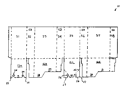
Figure 1 depicts a detailed view of the unfolded box in accordance with the
invention.
Figure 2 depicts a bottom view of a partially folded box in accordance with
the
invention.
Figure 3 depicts a view of flaps in the locked position in accordance with the
invention.
Figures 4-9 depict a method of closing the box of Figure 1.
Detailed Description of the Invention
Referring now to Figure 1, an exemplary embodiment of the invention is
shown comprising an octagonal laminated box 10 in an unfolded fonm having a
locking flap system. Box 10 includes eight sidewall sections indicated as S1-
S8, and
four bottom sections or flaps indicated as 12a-d. The dotted lines indicate
fold lines
for assembling the box. Two of the flaps, 12a and 12c have edges that include
specially formed tabs 18 and 20, which allow the two flaps 12a and 12c to
interconnect and secure the bottom of box 10.
Flap 12a comprises a generally trapezoidal shaped tab 18 with inwardly
projecting grooves 24. Also included on flap 12a is a pair of receiving tabs
25 which
are cut away from tab 18. Flap 12c comprises a generally trapezoidal shaped
tab 20
with outwardly projecting grooves 26. Also included on flap 12c is a pair of
locking
tabs 27, which are cut toward the tab 20. Flap 12c includes a pair of fold
lines 22 that
NORA-0001 3

CA 02462249 2007-12-11
facilitates interlocking between flaps 12a and 12c. When the flaps are brought
together and corners are diagonally folded along lines 22 of flap 12c, the
flaps
interlock, forming a solid connection that cannot be separated without
considerable
effort or tearing.
Sections S3 and S7 also include bottom flaps 12b and 12d. Each flap includes
an extended portion 28, 30 and a recessed portion 29, 31, thus forming a
generally L-
shaped edge. Flaps 12b and 12d overlap and interlock, as described below.
Figure 2 depicts a bottom view of box 10 in a partially folded state. As can
be
seen, when the box is folded, flap 12a meets up with 12c, allowing tab 18 to
interlock
with tab 20. Utilizing this design, the bottom flaps 12a-d of box 10 can be
locked
together without tape, staples, etc. Moreover, the resulting self-locking
design will not
protrude through to the inside bottom of box 10 to create an uneven bottom
surface.
Instead, this design provides a virtually smooth bottom inside the box, as the
locking
system is totally implemented on the outside of box 10.
To fold box 10, flaps 12b and 12d are first folded together such that the
extended portions 28 and 30 of the flaps interlock with the recessed portions
31 and
29, respectively, to form a generally flat surface on the bottom of box 10.
Next, flaps
12a and 12c are secured and locked together externally to flaps 12b and 12d.
Figure 3
depicts a view of the two flaps 12a and 12c interlocked together. As can be
seen, tab
20 of flap 12c sits on top of tab 18 (not shown) of flap 12a, and receiving
tabs 25 of
flap 12a sit on top of flap 12c. The inwardly and outwardly projecting grooves
24, 26
of the two flaps join at locations 32 and 34.
Figures 4-9 depict a complete method of closing the bottom flaps of box 10. In
a first step, Figure 4 depicts the bottom of box 10 with the flaps 12a-d
extending
upward. Figure 5 depicts a second step in which flaps 12b and 12d are folded
4

CA 02462249 2004-03-29
inwardly, resulting in the configuration shown in Figure 6. Figure 7 depicts a
third
step in which the corners of flap 12c are folded as shown by the directional
arrows.
Figure 8 depicts a fourth step in which flaps 12a and 12c are interlocked,
resulting in
the configuration shown in figure 9.
While the invention is described with reference to 8-sided bulk container box,
it is understood that the described locking flap system could be used in other
applications, e.g., in a single wall four-sided box, to lock a box top or
side, etc. The
foregoing description of the preferred embodiments of the invention has been
presented for purposes of illustration and description. They are not intended
to be
exhaustive or to limit the invention to the precise form disclosed, and
obviously many
modifications and variations are possible in light of the above teachings.
Such
modifications and variations that are apparent to a person skilled in the art
are
intended to be included within the scope of this invention as defined by the
accompanying claims.
NORA-0001 5

Representative Drawing
A single figure which represents the drawing illustrating the invention.
Administrative Status

2024-08-01:As part of the Next Generation Patents (NGP) transition, the Canadian Patents Database (CPD) now contains a more detailed Event History, which replicates the Event Log of our new back-office solution.

Please note that "Inactive:" events refers to events no longer in use in our new back-office solution.

For a clearer understanding of the status of the application/patent presented on this page, the site Disclaimer , as well as the definitions for Patent , Event History , Maintenance Fee  and Payment History  should be consulted.

Event History

Description Date
Time Limit for Reversal Expired 2022-09-29
Letter Sent 2022-03-29
Letter Sent 2021-09-29
Letter Sent 2021-03-29
Common Representative Appointed 2019-10-30
Inactive: Late MF processed 2017-04-03
Letter Sent 2017-03-29
Grant by Issuance 2009-06-23
Inactive: Cover page published 2009-06-22
Pre-grant 2009-03-06
Inactive: Final fee received 2009-03-06
Notice of Allowance is Issued 2008-11-18
Letter Sent 2008-11-18
Notice of Allowance is Issued 2008-11-18
Inactive: Approved for allowance (AFA) 2008-10-28
Amendment Received - Voluntary Amendment 2007-12-11
Inactive: S.30(2) Rules - Examiner requisition 2007-06-11
Amendment Received - Voluntary Amendment 2006-08-21
Letter Sent 2006-03-09
Request for Examination Requirements Determined Compliant 2006-02-20
All Requirements for Examination Determined Compliant 2006-02-20
Request for Examination Received 2006-02-20
Letter Sent 2005-06-01
Inactive: Correspondence - Transfer 2005-03-23
Application Published (Open to Public Inspection) 2005-01-15
Inactive: Cover page published 2005-01-14
Inactive: Office letter 2004-08-31
Inactive: Single transfer 2004-07-27
Inactive: Correspondence - Formalities 2004-06-08
Inactive: First IPC assigned 2004-05-16
Inactive: IPC assigned 2004-05-16
Inactive: Courtesy letter - Evidence 2004-05-04
Inactive: Filing certificate - No RFE (English) 2004-04-28
Filing Requirements Determined Compliant 2004-04-28
Application Received - Regular National 2004-04-28

Abandonment History

There is no abandonment history.

Maintenance Fee

The last payment was received on 2009-03-27

Note : If the full payment has not been received on or before the date indicated, a further fee may be required which may be one of the following

  • the reinstatement fee;
  • the late payment fee; or
  • additional fee to reverse deemed expiry.

Please refer to the CIPO Patent Fees web page to see all current fee amounts.

Owners on Record

Note: Records showing the ownership history in alphabetical order.

Current Owners on Record
NORAMPAC SCHENECTADY, INC.
Past Owners on Record
THOMAS WEST
Past Owners that do not appear in the "Owners on Record" listing will appear in other documentation within the application.
Documents

To view selected files, please enter reCAPTCHA code :


To view images, click a link in the Document Description column. To download the documents, select one or more checkboxes in the first column and then click the "Download Selected in PDF format (Zip Archive)" or the "Download Selected as Single PDF" button.

List of published and non-published patent-specific documents on the CPD .

If you have any difficulty accessing content, you can call the Client Service Centre at 1-866-997-1936 or send them an e-mail at CIPO Client Service Centre.


Document
Description 
Date
(yyyy-mm-dd) 
Number of pages   Size of Image (KB) 
Abstract 2004-03-29 1 15
Description 2004-03-29 5 176
Claims 2004-03-29 3 78
Drawings 2004-03-29 4 53
Representative drawing 2004-05-17 1 7
Cover Page 2004-12-21 1 34
Description 2007-12-11 5 174
Claims 2007-12-11 6 192
Claims 2008-03-27 6 191
Cover Page 2009-05-27 1 34
Filing Certificate (English) 2004-04-28 1 158
Request for evidence or missing transfer 2005-03-30 1 101
Courtesy - Certificate of registration (related document(s)) 2005-06-01 1 104
Reminder of maintenance fee due 2005-11-30 1 110
Acknowledgement of Request for Examination 2006-03-09 1 177
Commissioner's Notice - Application Found Allowable 2008-11-18 1 163
Maintenance Fee Notice 2017-04-03 1 178
Late Payment Acknowledgement 2017-04-03 1 163
Commissioner's Notice - Maintenance Fee for a Patent Not Paid 2021-05-10 1 535
Courtesy - Patent Term Deemed Expired 2021-10-20 1 539
Commissioner's Notice - Maintenance Fee for a Patent Not Paid 2022-05-10 1 551
Correspondence 2004-04-28 1 25
Correspondence 2004-06-08 2 83
Correspondence 2004-08-31 1 34
Fees 2006-02-15 1 50
Fees 2007-02-21 1 51
Correspondence 2009-03-06 1 57
Fees 2009-03-27 1 61