Sélection de la langue

Search

Sommaire du brevet 2462249 

Énoncé de désistement de responsabilité concernant l'information provenant de tiers

Une partie des informations de ce site Web a été fournie par des sources externes. Le gouvernement du Canada n'assume aucune responsabilité concernant la précision, l'actualité ou la fiabilité des informations fournies par les sources externes. Les utilisateurs qui désirent employer cette information devraient consulter directement la source des informations. Le contenu fourni par les sources externes n'est pas assujetti aux exigences sur les langues officielles, la protection des renseignements personnels et l'accessibilité.

Disponibilité de l'Abrégé et des Revendications

L'apparition de différences dans le texte et l'image des Revendications et de l'Abrégé dépend du moment auquel le document est publié. Les textes des Revendications et de l'Abrégé sont affichés :

  • lorsque la demande peut être examinée par le public;
  • lorsque le brevet est émis (délivrance).
(12) Brevet: (11) CA 2462249
(54) Titre français: SYSTEME DE VERROUILLAGE DE RABAT DE BOITE
(54) Titre anglais: BOX FLAP LOCKING SYSTEM
Statut: Périmé et au-delà du délai pour l’annulation
Données bibliographiques
(51) Classification internationale des brevets (CIB):
  • B65D 5/36 (2006.01)
  • B65D 5/18 (2006.01)
(72) Inventeurs :
  • WEST, THOMAS (Etats-Unis d'Amérique)
(73) Titulaires :
  • NORAMPAC SCHENECTADY, INC.
(71) Demandeurs :
  • NORAMPAC SCHENECTADY, INC. (Etats-Unis d'Amérique)
(74) Agent: MARKS & CLERK
(74) Co-agent:
(45) Délivré: 2009-06-23
(22) Date de dépôt: 2004-03-29
(41) Mise à la disponibilité du public: 2005-01-15
Requête d'examen: 2006-02-20
Licence disponible: S.O.
Cédé au domaine public: S.O.
(25) Langue des documents déposés: Anglais

Traité de coopération en matière de brevets (PCT): Non

(30) Données de priorité de la demande:
Numéro de la demande Pays / territoire Date
10/800,588 (Etats-Unis d'Amérique) 2004-03-15
60/487,353 (Etats-Unis d'Amérique) 2003-07-15

Abrégés

Abrégé français

L'invention, une boîte pliable à système de verrouillage de rabat de boîte comprenant un premier rabat ayant un rebord dans lequel une languette généralement trapézoïdale est découpée, la languette généralement trapézoïdale est délimitée par deux rainures vers l'intérieur; et un second rabat se verrouille dans le premier rabat, le second rabat comprend un rebord dans lequel une languette généralement trapézoïdale est découpée, la languette généralement trapézoïdale est délimitée par deux saillies vers l'extérieur.


Abrégé anglais

The invention provides a foldable box design having a box flap locking system, comprising: a first flap having an edge with a generally trapezoidal shaped tab cut therein, wherein said generally trapezoidal shaped tab is defined by two inwardly projecting grooves; and a second flap that locks with the first flap, wherein the second flap includes an edge with a second generally trapezoidal shaped tab cut therein, and wherein said second generally trapezoidal shaped tab is defined by two outwardly projecting grooves.

Revendications

Note : Les revendications sont présentées dans la langue officielle dans laquelle elles ont été soumises.


The embodiments of the invention in which an exclusive property or privilege
is
claimed are defined as follows:
1. A foldable box having a flap locking system, comprising:
a first flap having an edge with a generally trapezoidal shaped tab cut
therein,
wherein said generally trapezoidal shaped tab is defined by two inwardly
projecting
grooves that project toward each other and are substantially parallel to the
edge of the
first flap; and
a second flap that locks with the first flap, wherein the second flap includes
an
edge with a second generally trapezoidal shaped tab cut therein, and wherein
said
second generally trapezoidal shaped tab is defined by two outwardly projecting
grooves that project away from each other and are substantially parallel to
the edge of
the second flap, and wherein the second flap includes diagonal folds that
project from
the two outwardly projecting grooves to opposed edges of the second flap.
2. The foldable box design of claim 1, wherein the flaps reside on an outside
portion
of the bottom of the box when assembled.
3. A one-piece, collapsible container, comprising:
a plurality of side wall panels foldably joined to each other;
a plurality of flaps, each flap being foldably joined to an edge of an
associated
one of said side wall panels; and
an interlocking mechanism residing on first and second opposing flaps of the
plurality of flaps, wherein:
the first opposing flap includes an outer edge with a first tab cut
therein, wherein the first tab is defined by two inwardly projecting grooves
6

that project toward each other and are substantially parallel to the edge of
the
associated side wall panel; and
the second opposing flap locks with the first opposing flap, and
includes an outer edge with a second tab cut therein, wherein the second tab
is
defined by two outwardly projecting grooves that project away from each
other and are substantially parallel to the edge of the associated side wall
panel; and
wherein the collapsible container, when assembled, is octagonal in shape, and
the side wall panels comprise four opposing pairs of foldably joined panels.
4. The container of claim 3, wherein the second opposing flap includes folds
to
facilitate interlocking between the first and second opposing flaps.
5. The container of claim 3, wherein the flaps containing the interlocking
mechanism
reside on an outside portion of a bottom of the box when assembled.
6. The container of claim 3, further comprising a third and fourth opposing
flaps, said
third and fourth opposing flaps being shaped to permit their partial overlap
and
formation of a substantially flat surface.
7. The container of claim 6, wherein the third and fourth opposing flap is
each
substantially "L-shaped."
8. The container of claim 3, wherein the first and second tabs are trapezoidal
shaped.
7

9. A one-piece, collapsible container, comprising:
a plurality of side wall panels foldably joined to each other;
a plurality of flaps, each flap being foldably joined to an edge of an
associated
side wall panel; and
an interlocking mechanism residing on a first and second opposing flaps of the
plurality of flaps, wherein:
the first opposing flap includes an outer edge with a first tab cut
therein, wherein the first tab is defined by two inwardly projecting grooves
that project toward each other and are substantially parallel to the edge of
the
associated side wall panel; and
the second opposing flap locks with the first opposing flap, and
includes an outer edge with a second tab cut therein, wherein the second tab
is
defined by two outwardly projecting grooves that project away from each
other and are substantially parallel to the edge of the associated side wall
panel; and
wherein opposing third and fourth flaps are shaped to permit their partial
overlap and formation of a substantially flat surface.
10. A one-piece, collapsible container, comprising:
a plurality of side wall panels foldably joined to each other;
a plurality of flaps, each flap being foldably joined to an edge of one of the
side wall panels; and
interlocking tabs cut into an outer edge of both a first and second opposing
flaps of the plurality of flaps;
8

wherein at least one of the first and the second opposing flaps includes
diagonal folds that project from the interlocking tab to a central portion of
opposed
side edges of the flap to facilitate interlocking between the first and second
opposing
flaps.
11. A one-piece, collapsible container, comprising:
a plurality of side wall panels foldably joined to each other;
a plurality of flaps, each flap being foldably joined to an edge of one of the
side wall panels; and
interlocking tabs provided on a first and second opposing flaps of the
plurality
of flaps;
wherein a third and fourth opposing flaps comprise "L-shaped" flaps to permit
their partial overlap and formation of a substantially flat surface, wherein
each L-
shaped flap includes a pair of fold lines that run from the side wall panels
to an outer
edge of the L-shaped flap.
12. A foldable box having a flap locking system, comprising:
a first flap having first cutout regions removed along a first edge to form a
pair
of receiving tabs and a first generally trapezoidal shaped tab between the
receiving
tabs, wherein said generally trapezoidal shaped tab projects outwardly towards
the
first edge and includes two inwardly projecting grooves formed from the first
cutout
regions along a first common axis;
a second flap having second cutout regions removed along a second edge to
form a pair of locking tabs and a second generally trapezoidal shaped tab
between the
9

locking tabs, wherein each locking tab includes an outwardly projecting groove
formed from the second cutout regions along a second common axis; and
wherein when the flap locking system is secured, the second generally
trapezoidal shaped tab substantially overlaps and covers the first generally
trapezoidal
shaped tab and the receiving tabs substantially overlap and cover the locking
tabs.
13. An interlocking mechanism implemented on opposing edges of a first member
and a second member, wherein:
the first member includes an edge with a first trapezoidal shaped tab cut
therein, wherein the first trapezoidal shaped tab projects outwardly towards
the edge
and is defined by two inwardly projecting grooves that extend toward each
other
along a first common axis;
the second member locks with the first member and includes an edge with a
second trapezoidal shaped tab cut therein, wherein the second trapezoidal
shaped tab
projects outwardly towards the edge of the second member, and wherein the
second
member includes two outwardly projecting grooves that extend away from each
other
along a second common axis; and
the second trapezoidal shaped tab substantially overlaps and covers the first
trapezoidal shaped tab when secured.
14. The interlocking mechanism of claim 13, wherein the first member further
includes a pair of receiving tabs that are cut away from the first trapezoidal
shaped tab
and the second member further includes a pair of locking tabs that are cut
toward the
second trapezoidal shaped tab, and wherein the pair of receiving tabs
substantially
overlap and cover the locking tabs when secured.

15. An interlocking mechanism implemented between opposing members,
comprising:
a first member having a first outer edge and a pair of first side edges, the
first
member including a first trapezoidal shaped tab cut in the first outer edge
and a pair of
receiving tabs formed along the first pair of side edges, wherein the first
trapezoidal
shaped tab projects outwardly towards the first outer edge;
a second member having a second outer edge and a second pair of side edges,
the second member including a second trapezoidal shaped tab cut in the second
outer
edge and a pair of locking tabs formed along the second pair of side edges,
wherein
the second trapezoidal shaped tab projects outwardly towards the second outer
edge;
and
wherein the second trapezoidal shaped tab substantially overlaps and covers
the first trapezoidal shaped tab when the first and second member interlock.
11

Description

Note : Les descriptions sont présentées dans la langue officielle dans laquelle elles ont été soumises.

CA 02462249 2007-12-11
BOX FLAP LOCKING SYSTEM
BACKGROUND OF THE INVENTION
1. Technical Field
The present invention relates generally to foldable containers, and more
specifically relates to a box flap locking system.
2. Related Art
The ability to securely lock flaps of a foldable cardboard box (or similar
type
container) remains an ongoing problem. The problem is particularly challenging
for a
bottom side of the box where significant weight and stress can occur. For
instance, in
an 8-sided box, current designs utilize flaps that can easily become
disengaged wlien
stresses are place onto a loaded box. Accordingly, tape or other means, such
as lock
tabs, are required to hold the bottom flaps securely together. However,
current lock
tab designs protrude up and through the bottom inside of the box and can, for
instance, catch on and tear a poly liner often used within boxes. Accordingly,
a need
exists for a foldable box design that included flap that can be securely
locked without
interfering with the interior space of the box.
1

CA 02462249 2004-03-29
Summary of the Invention
The present invention addresses the above-mentioned problems, as well as
others, by providing a foldable box design having a box flap locking system.
In a first
aspect, the invention provides a foldable box having a flap locking system,
comprising: a first flap having an edge with a generally trapezoidal shaped
tab cut
therein, wherein said generally trapezoidal shaped tab is defined by two
inwardly
projecting grooves; and a second flap that locks with the first flap, wherein
the second
flap includes an edge with a second generally trapezoidal shaped tab cut
therein, and
wherein said second generally trapezoidal shaped tab is defined by two
outwardly
projecting grooves.
In a second aspect, the invention provides a one-piece, collapsible container,
comprising: a plurality of side wall panels foldably joined to each other; a
plurality of
flaps, each flap being foldably joined to an edge of a side wall panel; and an
interlocking mechanism residing on a first and second opposing flaps, wherein:
the
first opposing flap includes an edge with a first tab cut therein, wherein the
first tab is
defined by two inwardly projecting grooves; and the second opposing flap locks
with
the first opposing flap, and includes an edge with a second tab cut therein,
wherein the
second tab is defined by two outwardly projecting grooves.
In a third aspect, the invention provides an interlocking mechanism residing
on a first and second opposing member, wherein: the first member includes an
edge
with a first trapezoidal shaped tab cut therein, wherein the first trapezoidal
shaped tab
is defined by two inwardly projecting grooves; and the second member locks
with the
first member and includes an edge with a second trapezoidal shaped tab cut
therein,
wherein the second trapezoidal shaped tab is defined by two outwardly
projecting
grooves.
NORA-0001 2

CA 02462249 2004-03-29
Brief Description of the Drawings
These and other features of this invention will be more readily understood
from the following detailed description of the various aspects of the
invention taken in
conjunction with the accompanying drawings in which:
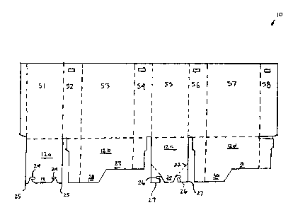
Figure 1 depicts a detailed view of the unfolded box in accordance with the
invention.
Figure 2 depicts a bottom view of a partially folded box in accordance with
the
invention.
Figure 3 depicts a view of flaps in the locked position in accordance with the
invention.
Figures 4-9 depict a method of closing the box of Figure 1.
Detailed Description of the Invention
Referring now to Figure 1, an exemplary embodiment of the invention is
shown comprising an octagonal laminated box 10 in an unfolded fonm having a
locking flap system. Box 10 includes eight sidewall sections indicated as S1-
S8, and
four bottom sections or flaps indicated as 12a-d. The dotted lines indicate
fold lines
for assembling the box. Two of the flaps, 12a and 12c have edges that include
specially formed tabs 18 and 20, which allow the two flaps 12a and 12c to
interconnect and secure the bottom of box 10.
Flap 12a comprises a generally trapezoidal shaped tab 18 with inwardly
projecting grooves 24. Also included on flap 12a is a pair of receiving tabs
25 which
are cut away from tab 18. Flap 12c comprises a generally trapezoidal shaped
tab 20
with outwardly projecting grooves 26. Also included on flap 12c is a pair of
locking
tabs 27, which are cut toward the tab 20. Flap 12c includes a pair of fold
lines 22 that
NORA-0001 3

CA 02462249 2007-12-11
facilitates interlocking between flaps 12a and 12c. When the flaps are brought
together and corners are diagonally folded along lines 22 of flap 12c, the
flaps
interlock, forming a solid connection that cannot be separated without
considerable
effort or tearing.
Sections S3 and S7 also include bottom flaps 12b and 12d. Each flap includes
an extended portion 28, 30 and a recessed portion 29, 31, thus forming a
generally L-
shaped edge. Flaps 12b and 12d overlap and interlock, as described below.
Figure 2 depicts a bottom view of box 10 in a partially folded state. As can
be
seen, when the box is folded, flap 12a meets up with 12c, allowing tab 18 to
interlock
with tab 20. Utilizing this design, the bottom flaps 12a-d of box 10 can be
locked
together without tape, staples, etc. Moreover, the resulting self-locking
design will not
protrude through to the inside bottom of box 10 to create an uneven bottom
surface.
Instead, this design provides a virtually smooth bottom inside the box, as the
locking
system is totally implemented on the outside of box 10.
To fold box 10, flaps 12b and 12d are first folded together such that the
extended portions 28 and 30 of the flaps interlock with the recessed portions
31 and
29, respectively, to form a generally flat surface on the bottom of box 10.
Next, flaps
12a and 12c are secured and locked together externally to flaps 12b and 12d.
Figure 3
depicts a view of the two flaps 12a and 12c interlocked together. As can be
seen, tab
20 of flap 12c sits on top of tab 18 (not shown) of flap 12a, and receiving
tabs 25 of
flap 12a sit on top of flap 12c. The inwardly and outwardly projecting grooves
24, 26
of the two flaps join at locations 32 and 34.
Figures 4-9 depict a complete method of closing the bottom flaps of box 10. In
a first step, Figure 4 depicts the bottom of box 10 with the flaps 12a-d
extending
upward. Figure 5 depicts a second step in which flaps 12b and 12d are folded
4

CA 02462249 2004-03-29
inwardly, resulting in the configuration shown in Figure 6. Figure 7 depicts a
third
step in which the corners of flap 12c are folded as shown by the directional
arrows.
Figure 8 depicts a fourth step in which flaps 12a and 12c are interlocked,
resulting in
the configuration shown in figure 9.
While the invention is described with reference to 8-sided bulk container box,
it is understood that the described locking flap system could be used in other
applications, e.g., in a single wall four-sided box, to lock a box top or
side, etc. The
foregoing description of the preferred embodiments of the invention has been
presented for purposes of illustration and description. They are not intended
to be
exhaustive or to limit the invention to the precise form disclosed, and
obviously many
modifications and variations are possible in light of the above teachings.
Such
modifications and variations that are apparent to a person skilled in the art
are
intended to be included within the scope of this invention as defined by the
accompanying claims.
NORA-0001 5

Dessin représentatif
Une figure unique qui représente un dessin illustrant l'invention.
États administratifs

2024-08-01 : Dans le cadre de la transition vers les Brevets de nouvelle génération (BNG), la base de données sur les brevets canadiens (BDBC) contient désormais un Historique d'événement plus détaillé, qui reproduit le Journal des événements de notre nouvelle solution interne.

Veuillez noter que les événements débutant par « Inactive : » se réfèrent à des événements qui ne sont plus utilisés dans notre nouvelle solution interne.

Pour une meilleure compréhension de l'état de la demande ou brevet qui figure sur cette page, la rubrique Mise en garde , et les descriptions de Brevet , Historique d'événement , Taxes périodiques et Historique des paiements devraient être consultées.

Historique d'événement

Description Date
Le délai pour l'annulation est expiré 2022-09-29
Lettre envoyée 2022-03-29
Lettre envoyée 2021-09-29
Lettre envoyée 2021-03-29
Représentant commun nommé 2019-10-30
Inactive : TME en retard traitée 2017-04-03
Lettre envoyée 2017-03-29
Accordé par délivrance 2009-06-23
Inactive : Page couverture publiée 2009-06-22
Préoctroi 2009-03-06
Inactive : Taxe finale reçue 2009-03-06
Un avis d'acceptation est envoyé 2008-11-18
Lettre envoyée 2008-11-18
Un avis d'acceptation est envoyé 2008-11-18
Inactive : Approuvée aux fins d'acceptation (AFA) 2008-10-28
Modification reçue - modification volontaire 2007-12-11
Inactive : Dem. de l'examinateur par.30(2) Règles 2007-06-11
Modification reçue - modification volontaire 2006-08-21
Lettre envoyée 2006-03-09
Exigences pour une requête d'examen - jugée conforme 2006-02-20
Toutes les exigences pour l'examen - jugée conforme 2006-02-20
Requête d'examen reçue 2006-02-20
Lettre envoyée 2005-06-01
Inactive : Correspondance - Transfert 2005-03-23
Demande publiée (accessible au public) 2005-01-15
Inactive : Page couverture publiée 2005-01-14
Inactive : Lettre officielle 2004-08-31
Inactive : Transfert individuel 2004-07-27
Inactive : Correspondance - Formalités 2004-06-08
Inactive : CIB en 1re position 2004-05-16
Inactive : CIB attribuée 2004-05-16
Inactive : Lettre de courtoisie - Preuve 2004-05-04
Inactive : Certificat de dépôt - Sans RE (Anglais) 2004-04-28
Exigences de dépôt - jugé conforme 2004-04-28
Demande reçue - nationale ordinaire 2004-04-28

Historique d'abandonnement

Il n'y a pas d'historique d'abandonnement

Taxes périodiques

Le dernier paiement a été reçu le 2009-03-27

Avis : Si le paiement en totalité n'a pas été reçu au plus tard à la date indiquée, une taxe supplémentaire peut être imposée, soit une des taxes suivantes :

  • taxe de rétablissement ;
  • taxe pour paiement en souffrance ; ou
  • taxe additionnelle pour le renversement d'une péremption réputée.

Veuillez vous référer à la page web des taxes sur les brevets de l'OPIC pour voir tous les montants actuels des taxes.

Titulaires au dossier

Les titulaires actuels et antérieures au dossier sont affichés en ordre alphabétique.

Titulaires actuels au dossier
NORAMPAC SCHENECTADY, INC.
Titulaires antérieures au dossier
THOMAS WEST
Les propriétaires antérieurs qui ne figurent pas dans la liste des « Propriétaires au dossier » apparaîtront dans d'autres documents au dossier.
Documents

Pour visionner les fichiers sélectionnés, entrer le code reCAPTCHA :


Pour visualiser une image, cliquer sur un lien dans la colonne description du document. Pour télécharger l'image (les images), cliquer l'une ou plusieurs cases à cocher dans la première colonne et ensuite cliquer sur le bouton "Télécharger sélection en format PDF (archive Zip)" ou le bouton "Télécharger sélection (en un fichier PDF fusionné)".

Liste des documents de brevet publiés et non publiés sur la BDBC .

Si vous avez des difficultés à accéder au contenu, veuillez communiquer avec le Centre de services à la clientèle au 1-866-997-1936, ou envoyer un courriel au Centre de service à la clientèle de l'OPIC.


Description du
Document 
Date
(aaaa-mm-jj) 
Nombre de pages   Taille de l'image (Ko) 
Abrégé 2004-03-29 1 15
Description 2004-03-29 5 176
Revendications 2004-03-29 3 78
Dessins 2004-03-29 4 53
Dessin représentatif 2004-05-17 1 7
Page couverture 2004-12-21 1 34
Description 2007-12-11 5 174
Revendications 2007-12-11 6 192
Revendications 2008-03-27 6 191
Page couverture 2009-05-27 1 34
Certificat de dépôt (anglais) 2004-04-28 1 158
Demande de preuve ou de transfert manquant 2005-03-30 1 101
Courtoisie - Certificat d'enregistrement (document(s) connexe(s)) 2005-06-01 1 104
Rappel de taxe de maintien due 2005-11-30 1 110
Accusé de réception de la requête d'examen 2006-03-09 1 177
Avis du commissaire - Demande jugée acceptable 2008-11-18 1 163
Avis concernant la taxe de maintien 2017-04-03 1 178
Quittance d'un paiement en retard 2017-04-03 1 163
Avis du commissaire - Non-paiement de la taxe pour le maintien en état des droits conférés par un brevet 2021-05-10 1 535
Courtoisie - Brevet réputé périmé 2021-10-20 1 539
Avis du commissaire - Non-paiement de la taxe pour le maintien en état des droits conférés par un brevet 2022-05-10 1 551
Correspondance 2004-04-28 1 25
Correspondance 2004-06-08 2 83
Correspondance 2004-08-31 1 34
Taxes 2006-02-15 1 50
Taxes 2007-02-21 1 51
Correspondance 2009-03-06 1 57
Taxes 2009-03-27 1 61