Note: Descriptions are shown in the official language in which they were submitted.
CA 02462483 2004-03-30
I~.~I~FC.aELJIZ ~ITI-.~( I)~T~lCj~3A.BT E CIZ~~SS~~d~
Continuing, Information
This application is a continuation-in-part of pending application Serial No.
09/q74.,4.04, filed ~ctober 10, 2~OI, the disclosure of which is hereby filly
incorporated
by reference.
Field of the Invention
The present invention relates to a rongeur, and more particularly to a rongeur
l0 having a detachable crossbar.
~ack~round
The rongeur is a medical instrument used. for a variety of proposes. It is
particularly useful for removing small amounts caf bor~c, cartilage or other
body material
t5 from inside small spaces of the knee or between vertebrae. A rongeur
usually includes a
long fixed shank with an anvil o:~ footplate at its distal end aru a handle at
its proximal
end. A cross bar slideably enga ges the shank and reciprocates thereon by
means of a
pivotable second handle. Cutting edges on the distal end of the crossbar bite
against the
footplate to cut away a small portion of tissue with each reciprocation of the
crossbar.
20 For precise operation of the instrument tight tolerances between the
rraating parts is
preferred. While enhancing prez~ise operation, these tolerances can make
effective
cleaning of the instrument difficult. Mood and c3~heg bodily rr-zatte~- with
becomes trapped
between the shank and crossbar can be difficult to remove. hailure to remove
Such matter
can lead to inco:npletP sterilization. 4.c:cordirzgly, it is desirable to
d'Ilow access to th~ae
25 parts during cleaning and sterili~.~ation.
The Janzen L.TS Patent ~Io. 6,1~6,b74, incorporated herein by reference,
attempts to
solve this problem by providing a removable crossbar. t~ slot in the; top of
the pivotable
handle receives a pin on the cro:9sbar. A rotating disc on the fixed r{andle
abuts a surface
on the pivotable handle to lirr~it spread between the handles. potation of the
disc into an
3o alternate orientation allow a slightly broader spread between the handles
allowing the
crossbar to move back distally csff of the pin anti to then be removed. In
such a design it
can be difficult to balance the force necessary to rotate the disc. if ~:he
force required is too
great it can be difficult to opera~.e and discourage disassembly prior to
sterilization. If the
CA 02462483 2004-03-30
force required is too low it can allow the device to disassemble accidentally
during normal
use.
Summary of the Invention
A rongeur according to the present invention overcomes these and other
limitations of the prior art. rt coanprises an elongated shank having a distal
end and a
proximal end and an elongated crossbar having a distal end and a pr~~ximal end
adapted to
reciprocate axially with respect i:o the shank. The crossbar has a
ret~°acted position
wherein the crossbar is partially retractcd proxirr~ally with re:~pect to the
shank and a
to retracted-release position wherein the crossbar is further retracted
proximally with respect
to the shank than in the retracted. position. Mating surfaces on the shank and
crossbar
align to block disengagement of the crossbar frorrl the shank in the retracted
positions and
come out of alignment to allow disengagement of the crossbar from the shank in
the
retracted-release position. ~ first handle is fixedly configured to the; shank
proximal end
t5 and a second handle pivotably attaches to the shank proximal end about a
pivot axis. A
slot in an upper portion of the second handle receives a pin affixed to the
crossbar at its
proximal end whereby pivoting of the second handle about the pivot axis
induces axial
movement of the pin to reciprocate the crossbar. Engagement betwaen the pin
and the slot
prevents the crossbar from retra~.aing to the retracting-release position. The
pin is
zo selectively moveable upwardly sufficiently out of the slot to allow further
proximal
movement of the crossbar with respect to the shank to the retracted-release
position
whereby to allow the crossbar tc> be disengaged a..nd removed from the sha~ak
for more;
effective cleaning and sterilization thereof. The pin is positioned on a
holding member on
tl~!e crossba.~, thP. holding :r:rrnb=.r having a farst position in which the
pin is sufficiently
25 deeply within the slot to prevenretraction of the crossbar to the retracted-
released
position and a second position in which the pin is sufficientl;y out of the
slot so as to allow
retraction of the crossbar to the retracted-release position. A stop screw has
a head and a
threaded shank. The threaded sham' is threadably engaged with the crossbar
between a
first position, which prevents movement of the holding member frovm its first
position to
3o its seeand position, and a second positions which permits mcmement of the
holding
member from its first position to its second position.
Preferably the mating sr:rfaces comprise an undercut slot on one of the shank
and
crossbar and a flange on the other of the shank and crossbar received within
the slot, and
CA 02462483 2004-03-30
more preferably the slot and flange are ~'-shaped. Preferably, a prox.irnal
portion of the
slot is not undercut.
Preferably, a detent engagement is provided between the holding member and the
crossbar when the holding member is in its first position, which engagement
can comprise
a spring ball. In one aspect of th.e invention, the holding member has a LT-
shaped cross
section and is received over the crossbar. The pin can penetrate an aperture
an the
crossbar to fix the holding member to the crossbar. Preferably, the crossbar
has a vertical
groove and the holding mer~lher has a rib on an inner surface thereof which
slides within
the vertical groove. '
1o Preferably, one or more of drainage apertures penetrate through the shank
adjacent
the faotplate. 'The drainage ape~.-tures can penetrate through the shank at
the slot.
Brief Description of the I7rawin~s
FIG. 1 is a frant elevatian view of a rangeur according to the present
invention;
FIG. 2 is a front elevatican view of a crossbar from the r~ngeur of FIG. 1;
is FIG. ~ is a bottom plan view of the crossbar of FIG. 2;
FIG. 4 is an exploded perspective view of a locking ~rra~.eclxanism of the
rongeur of
FIG. 1;
FIG. 5 is a perspective detail view of a footplate on the rongeur of FIG. 1
FIG. 6 is a cross sectior!.al view taken along Iines 6--6 of FIG. 2;
2~ FIG. 7 is a front elevation view of the rangeur of FIG. 1 showing the
locking
mechanisrrr in the unlocked orientation;
FIG_ R 7s a bottom Man view of a distal portion of the roragc;ur of FIG. 1;
FIG. 9 is a partial exploded view showing the holding member and safety screw
in
accordance witl-a snotW.r eaiauU'~liiW:a .".f the ~:.re~'aWt lnVentlofl;
25 FTG. 10 is an exploded front elevation view of the crossbar of FIG. 9;
FIG. 11 is front elevation view of the crossbar of FTG. g;
FIG.12 is a cross secticonal view taken along lines 1:~-12 of FIG. I 1;
FTG. l~ is a partial front elevation view of the holding member in its first
position;
and
3o FIG. I~ is a partial front elevation view, with parts broken away, of the
holding
member in its second pasition.
_;_
CA 02462483 2004-03-30
Detailed Descritstion
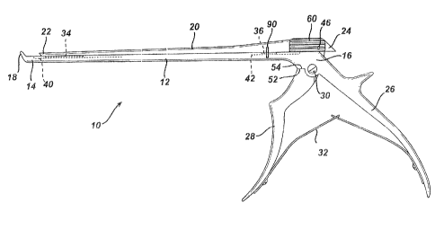
FIG. 1 illustrates a rongeur 10 according to the present invention. It
comprises an
elongated shank 12 laving a dist31 end 14 and proximal end 16. A footplate 18
extends
upwardly from the shank 12 at its distal end 14. .,~ crossbar 20 slideably
engages the
shank 12 and also comprises a distal end 22 and proximal end 24. A first
handle 26
extends downwardly from the shank proximal end 15 in fixed relation to the
shank 12. A
second handle 28 pivotably attaches to the shank 12 near its proximal end 16
and pivots
about an axis 30. A spring 32 between the first and second handles 26 and 28
biases them
apart.
As further seen in F ICsS. 2 and 3, distal and proximal 'T-shaped splines 34
and 36,
respectively, on a lower surface 38 of the crossbar 20 fit within respective
distal and
proximal T-shaped slots, 40 and 42, respectively, on an upper surface 44 of
the shank 12
to allow slideable axial movement between the crossbar 20 ay.~d sha:ak 12
without allowing
the crossbar 20 to lift off of tle clank 12. It will be appreciated by one of
skill in the art
that the locations of the splines :~.nd slots can be reversed and that other
engaging shapes
can be substituted therefor.
Turning further to FI~'a. 4, a pin 46 on the crossbar 20 rides ewithin a slot
48 orc an
upper portian 50 of the second handle 28 so that when the sE;cond landle 28 is
squeezed
toward the first handle 26 by an. operator the slot 48 moves distally and tle
action of the
2C! pin 46 therein drives the crossbar 20 distally. Turning further to FI:Ca.
5, the footplate 18
comprises an anvil cutting surface 45 about a tissue receiving recess 47 and a
stress
relieving grootye 40 >?et~.x'een ti,° footplate ~ ~ anal shank 12 as
snore fully described in US
patent No. 4,990,148 to t~orrick, III et al., fully incorporated lerein by
reference. Cutting
edges 51~ on the distal end 22 of tl:e crossbar 20 v:~gage thr anvil se.zrface
45 whereby
tissue, as for instance bone, traaped therebetwevn is cut.
It is advantageous to disassemble the rongeur 10, by removing the crossbar 20,
prior to cleaning and sterilizing. Focusing primarily upon FIG. 4, removal of
the crossbar
20 is effected by moving the p.m 46 upwardly out of the slot 48. Contact
between a handle
abutment surface 52 on the second handle 28 and a shank abutment surface 54 on
the
3o shank 12 Iirnits rotation of the second handle 28 and thus effectively
limits rearward or
proximal mo~~ement of the crossbar 20. Proximal portions 66 and 58
respectively of the
distal slot 40 and proximal slot 42 are open, not T-shaped, so as to allow
disengagement of
the splines 34 and 36 from the slots 40 and 42 and thereby allow the crossbar
20 to be
lifted off of the shank 12. To disengage the splines 34 and 36 they must be in
register with
..
CA 02462483 2004-03-30
the proximal portions 56 and 58. However9 abrztn~ent of the h,~.ndle arid
shank abutment
surfaces 52 and 54 limits proximal movement of the crossbar :~0 s~.ff~:ciently
to disallow
registry of the splines 34 and 36 with the proximal portions 56 and S8. loving
the pin 46
upwardly out of the slot 48 allows further proximal movement of the crossbar
20 so as to
allow registry of the splines 34 arid 36 with the proximal portions S6 and 58
and thus
removal of the crossbar 20.
El locking mechanism 60 maintains the pin 46 within the slot 48 and allows its
selective movement thereout. The locking mechanism 60 connprises a channel
member 62
having a lower channel 64 which fits over a recessed portion 66 of the
crossbar 20 near its
1o proximal end 24. Vertically oriented guiding grooves 68 on the recessed
portion 66
receive mating tongues 70 to guide vertical movement of the channel member 62
on the
crossbar 20. The pin 46 passes ?aterally throwgh the channel rrternber 62 and
is affixed
thereto. A. spring ball plunger 7 ~ on the received within an aperture 74 on
the crossbar
comprises a caged ball 76 and spring 78 (see also FIG. 6). The ball '76
engages a dimple
is 80 on an inner surface of the charnel 64 to hold the channel
rnember° in a lowered position.
8uffrcient upward force on the cW nnel member 62 disengage;s thg: b;~ll
°76 from the dimple
80 to allow the channel member 6? to move upwardly.
As primarily seen in FIGS. 2 and 4, an arcuate underc~;xt cizarnber 82 on the
crossbar 20 receives the second handle upper portion 50. The pin 46 passes
through
2o elongated vertical slots 84 in the crossbar 20 and sits in the slot 48 in
the second handle
upper portion 50. With the pin ~~6 trapped in the elongated slots 84 the
channel member
62 is thus held to the crossbar ?0, a :'e.~. ~.~~~e:: lifie~? tr a.: y.:prP~-
pvsa:iva as shown in FIG.
7. preferably, gripping erahancernents such as ribbing 86 shown in hIG. 4 is
provided ~n
the channel member 62.
25 Taming primarily to F1G. 8, drainage holes 88 penetrate the shank 12 near
its
distal end 14. These drainage holes allow drainage ofblood and bodily fluids
during use
and allow drainage during cleaning. e~he y may be countersunk on a surface 92
facing the
crossbar 20 as shown in FIG. 5 to encourage drainage into the holea 88.
Further, the
surface 92 can be sloped tos~.-ard the holes 88 to enhance drainage
therethrough.
30 In use, the first and second ha~adles Z6 and 28 are squeezed 'together to
move the
second handle upper portion. 5G distally thereby engaging the pin 4c5 and
driving tree
crossbar 20 distally. The cutting edgc;s 51 on the crossbar distal end 22 move
toward the
anvil 45 and tissue (not shown) trapped therebet~veen is cut away. Typically,
many
successive cuts are made in one procedure. Blood and bodily fluid within the
distal slot 40
_;_
CA 02462483 2004-03-30
are allowed to pass out through the drainage holes 88. Aftei the cutting
procedure is over,
the channel member 62 is lifted up and the crossbar moved proximally to a
retracted
release position, as shown in phantom in FIG. 7. Tn this position the T-shaped
splines 34
and 3b align with the open proximal portions 56 and S8 of the slots 40 and 42.
The
crossbar 20 is then lifted free of the shank 12. Cleaning and sterilization of
the rongeur I0
is effected in this disassembled state.
To reassemble the rongeur I0, the channel member 62 is placed in its upward
position and the splines 34 and ash are moved into the proximal portions 56
and S8 of the
slots 40 and 42. The crossbar is moved distally to engage th:e T-shaped
splines ~4 and 36
1o within the T-shaped slots 40 and 42 and to place the pin 46 i,n location
over the slot 48 on
the second handle upper portiorx S0. A pair of alignment marks 90 on the shank
I2 and
crossbar 20 can be provided to assist in locating this position. Then, the
channel member
is pressed down to engage the pin 46 into the slot 48 and the spring; ball
plunger '72 into
the dimple 80.
is Referring now to FIGS. 9-14, another embodiment of the present invention is
illustrated. This embodiment i~lcorporates a stop screw I 10 to prevent
inadverkent upward
movement of the holding rne~n~~er 60. because most of the elements in this
embodiment
are identical to those discussed above, for the sake of brevity in thp~
disclosure, only those
elements that vary from the above embodiment will be discussed in detail. A
stop screw
2o I 10 has a head I 16 and a threaded shank I 18. The threaded shank 118
threadably engages
a threaded bore 114 within the crossbar 20. T'I~ireaded shank is axially
movable within
bore 114 between a first position (see FIGS I 1-13~, wl~.~;,h p.,re~,~e;:tv
::wdrer': ef the
holding member 60 from its first lovrered position to its second upward
position, and a
s~co. d positiVa., Yrhich permits movement of the holding member 60 from its
farst lowered
'5 position to its second upward position. holding member 60 has an aperture
120.
'Threaded shank 118 passes through aperture I20 in holding r:~ember 60. A
distal end of
the threaded shank 118 remote from head 116 has a radially outwardly flared
end 1 I2 to
prevent screw 110 from beir~~; removed from crossbar 20.
The invention now being fully described, it will be apparent to one of
ordinary skill
3o in the art that many modifications and changes can be made thereto without
departing
from the spirit or scope of the invention as defined in the following claims.
_~;_