Note: Descriptions are shown in the official language in which they were submitted.
CA 02462820 2004-03-31
ITW-13911
METHOD AND APPARATUS FOR
INITIATING WELDING ARC WITH
AID OF VAPORIZED CHEMICAL
BACKGROUND OF THE INVENTION
This invention generaAy relates to methods and apparatus for
starting a welding arc. In particular, the invention relates to methods and
apparatus for starting a TIG welding arc.
Many methods of welding are known in the art, each with its own
advantages and disadvantages. Common welding processes include gas
welding, oxyacetylene brazing and soldering, shielded metal arc welding
(SMAW) or "STICK°' welding, gas metal arc welding (GMAW) or "wire feed"
welding, gas tungsten arc welding (GTAW) or "TIG'° welding, and plasma
cutting. T1G welding is perhaps the cleanest, most precise of all hand-held
welding operations. Although the method and apparatus of the present
invention is preferably directed to a TIG welding operation, one skilled in
the art
will appreciate that the present invention may have applications for many
other
welding processes.
A conventional TIG welding process will naw be described with
reference to FIG. 1. In TIG welding, a concentrated high-temperature arc is
drawn between a non-consumable tungsten electrode 10 and a workpiece 14,
workpiece 14 being connected to the output of a welding power source (not
shown) via a work clamp 24. Electrode 10 is nested in a torch 16, the torch
including a shielding gas source 18, such as a cup, to direct a shielding gas
20,
such as argon, helium, a mixture thereof, or other inert or non-inert gases,
to a
welding site 22 on workpiece 14. Torch 16 receives a flow of shielding gas 20
from a gas tank (not shown). In accordance with a known technique, the welder
may strike an arc by touching or scraping the electrode 10 against the
workpiece 14 to close a circuit between the electrode 10 and the work clamp
24. As electrode 10 is drawn away from the workpiece 14, an arc 12 is
initiated.
The welder then feeds a bare welding rod 25 to welding site 22. More
precisely,
1,
CA 02462820 2004-03-31
the tip of the welding rod 26 is dipped into the weld puddle. The arc that
crosses the gap from the electrode tip to the workplace causes underlying
workplace material at the welding site to melt, thereby creating a molten
puddle
28. During a single welding pass, the arc 12 and the welding rod 26 must be
moved in unison in order to effect a weld bead. The displaced arc leaves the
molten puddle 28 in its wake. The portion of the molten puddle furthest from
the
arc hardens continuously to leave a weld bead 30 joining two pieces of metal.
Numerous problems persist with the aforementioned physical
method of striking an arc because the tip of the tungsten can contaminate the
weld due to touching or scraping the electrode against the workplace. Often,
due to arcing a piece of the tip remains in the molten puddle and contaminates
the weld. Also, the welder must then resharpen or replace the electrode. Not
only does this process inconvenience the welder, but it also wastes time and
resources, which ultimately imparts a higher cost to each weld.
One known solution to the above problems has been to use a
high-frequency signal to initiate and maintain the arc. A high-frequency
signal
ionizes the shielding gas, allowing the welding power to jump the gap between
electrode and workplace. However, high frequency, too, has its drawbacks. The
high-voltage, low-amperage noise from the high-frequency circuitry often
causes electrical interference with surrounding equipment, making its use
unacceptable in certain applications. Also, the high-frequency signal can be
tough on TIG torches and work leads because the high voltage causes a stress
to be applied to the insulation of the weld cables.
Another arc starting method that avoids the problems associated
with the scratch start is the "lift" arc method. Lift arc starting involves
touching
the electrode to the workplace without the necessary scraping to generate a
spark. Some known lift arc methods utilize a separate low-current power
circuit,
in addition to the power circuits already present in a welding device, to
create a
smaPl monitoring voltage between the electrode and work clamp. Control
34 circuitry monitors the voltage between the electrode and work clamp and,
when
2
CA 02462820 2004-03-31
' ' a short is detected (i.e., the electrode has been touched to or brought in
close
proximity with the workpiece), enables the power circuit to provide an initial
regulated current to warm, but not melt the electrode. When the control
circuitry
detects a significant torch-to-workplace voltage (i.e., the electrode is no
longer
touching or is not in close proximity to the workplace), the control circuitry
enables the power circuit to provide full user-selected welding power.
However,
the separate power circuit required to provide the small monitoring voltage
leads to additional cost and complexity of the circuitry in the welding power
source. Furthermore, some lift arc start methods fail to reliably regulate the
output current level before and after the short is detected. An improved
"lift" arc
technique, directed to overcoming the foregoing disadvantages, is disclosed in
U.S. Patent No. 6,034,350. Still some welding procedures require that the
tungsten not touch the workplace.
Another known solution, disclosed in U,.S. Patent No. 6,075,224,
is to start a welding arc by applying an arc starting signal to ionize the
shielding
gas before enabling welding output power. The welding device disclosed in
U.S. Patent No. 6,075,224 comprises a power circuit to provide welding power,
a shielding gas source to provide a shielding gas at a welding site disposed
between an electrode and a workplace, an arc starter circuit (e.g., a high-
frequency start circuit) to apply an arc starting signal to ionize the gas,
and a
controller coupled to a control input of the power circuit. The arc starting
steps
are also controlled by the controller. First, the controller enables a flow
control
meter to begin supplying shielding gas to the welding site. When the pre-flow
period has expired, the controller enables the arc starter circuit, which
generates an arc starting signal that is provided to the power output far a
predetermined period of time during which the resulting arc ionizes the flow
of
shielding gas particles. The starting arc is not suitable for welding. A
predetermined time after the arc starting signal is applied, the controller
enables
the power circuit such that welding power is provided and an arc suitable for
welding is drawn between the electrode and the workplace.
3
CA 02462820 2004-03-31
There is an ongoing need for further improvements in methods
and apparatus for initiating and maintaining a TIG or othier welding arc.
BRIEF DESCRIPTION OF TIE INVENTION
The invention is directed to methods and apparatus for initiating
an arc (e.g., a welding arc) by directing a beam of electromagnetic radiation
at
an ionizable chemical placed on the surface of a workpiece. This is done while
a potential difference is applied between an electrode and the workplace that
are separated by a gap. The radiation vaporizes the chemical to form ionized
gas that renders the gap between the electrode and the workplace more
conductive, thereby reducing the voltage threshold needed to initiate an arc
between the electrode and the workplace. When the voltage threshold reaches
the level of the applied potential difference, the arc will be initiated.
One aspect of the invention is a method of initiating an arc
between an electrode and a workplace separated by a gap, comprising the
following steps: applying a potential difference between the electrode and the
workplace; placing a chemical that produces ions when vaporized in the
vicinity
of or near the gap; and directing a laser beam toward the chemical with
sufficient power to vaporize enough chemical to produce an arc between the
electrode and the workplace at the applied potential difference.
Another aspect of the invention is a method of initiating an arc
between an electrode and a workplace separated by a gap, comprising the
following steps: applying a potential difference between the electrode and the
workplace; placing an ionizable chemical in the vicinity of or near the gap;
and
directing sufficient electromagnetic radiation onto the ionizable chemical to
vaporize chemical in an amount that causes an arc to be produced between the
electrode and the workplace at the applied potential difference.
A further aspect of the invention is an apparatus comprising: an
electrode comprising a tip; a shield surrounding the electrode to form a
passageway therebetween; and a laser disposed to transmit a laser beam
4
CA 02462820 2004-03-31
along a line that generally intersects an axis of the electrode at a position
below
the tip of the electrode.
Yet another aspect of the invention is a system comprising: an
electrode comprising a tip; a workpiece comprising a surFace area separated
from the tip of the electrode by a gap and covered by an ionizable chemical; a
power circuit for applying a predetermined potential difference between i;he
electrode and the workpiece; and a beam transmitter for transmitting a beam of
electromagnetic radiation at the ionizable chemical on the surface area.
A further aspect of the invention is a method for initiating an arc
between an electrode and a workpiece separated by a gap, comprising the
following steps: placing an ionizable chemical in solid form on a surFace area
of
the workpiece confronting the electrode; applying a potential difference
between the electrode and the workpiece; and vaporizing enough of the
ionizable chemical to produce an arc between the electrode and the workpiece
at the potential difference.
Other aspects of the invention are disclosed and claimed below.
BRIEF DESCRIPTION OF THE DRAW INGS
FIG. 1 is a drawing illustrating a conventional TIG welding
operation, described in the Background of the Invention section.
FIG. 2 is a drawing showing a partial sectional view of an
apparatus comprising a laser and a TIG welding torch in accordance with tine
embodiment of the present invention.
Reference will now be made to the drawings in which similar
elements in different drawings bear the same reference numerals.
DETAILED DESCRIPTION OF THE INVENTION
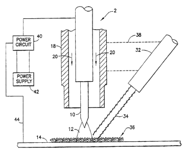
The basic concept of the invention is illustrated in FIG. 2, which
shows a setup for TIG welding arc initiation. The workpiece 14 is positioned
5
CA 02462820 2004-03-31
'with the welding site disposed directly underneath the tip of a tungsten
electrode 10 of a TIG welding torch 2. The electrode 10 receives electrical
power from a power supply 42 via a power circuit 40. When the power circuit 40
is turned on, the power supply 42 produces a difference in the electric
potentials at the electrode 10 and the workpiece 14 respectively. During
welding arc formation, the electrode 10 receives current via the power circuit
40. A workpiece lead 44 provides a return path for the current and is
typically
connected to the workpiece 14 by a clamp (not shown). In the absence of an
arc, current does not flow through the electrode and the workpiece.
The TIG welding torch 2 further comprises a generally circular
cylindrical gas cup or shield 18 that surrounds and is generally coaxial with
the
electrode 10. The cup 18 defines the outer boundary of a generally annular
passageway through which a shielding gas, such as argon, helium, a mixture
thereof, or other inert or non-inert gas, flows. The shielding gas flow is
indicated
by arrows 20 in FIG. 2. The shielding gas is conveyed to the welding torch
from
a gas supply tank by means not shown, which means typically include a cable
that connects the welding torch to the power supply unit. Typically the cable
carries both shielding gas and electric power to the welding torch.
To initiate an arc in accordance with one embodiment of the
invention, the flow of shielding gas is turned on, arid a potential difference
between the electrode 10 and the workpiece 14 is applied. Initially, the
conditions are such that an arc is not initiated, i.e., the resistance across
the
gap separating the tip of electrode 10 and the workpiece 14 is too great
relative
to the potential difference or voltage being applied. The present invention
employs means for increasing the conductivity of the gap to a point whereat
the
arc will be initiated at the applied voltage.
FIG. 2 depicts an instant in time immediately following initiation of
a welding arc 12 between the electrode 10 and the workpiece 14. In
accordance with the embodiment depicted in FIG. 2, the welding arc is
initiated
with the aid of a laser 32, shown disposed at an oblique angle relative to
bath
6
CA 02462820 2004-03-31
the TIG welding torch 2 and the workpiece 14. The laser 32 operates in
conventional fashion to generate a beam 34 of subs>tantially monochromatic
electromagnetic radiation, which is typically in the optical or infrared
range. The
laser beam 32 is directed toward the top surface of the workpiece 14 in the
area underlying the tip of the tungsten electrode 10. The laser 32 may be held
and aimed by the welder or may be supported in a fixed positional relationship
with the TIG torch, e.g., by means of a support member 38, the ends of which
are welded or clamped to the gas cup 18 and to the laser 32 respectively.
In accordance with one embodiment of the invention, the area
under the electrode is covered with solid matter 36 in particulate form. The
solid
matter 36 comprises a chemical having the property of being ionizable when
exposed to electromagnetic radiation of sufficient power. In other words, in
this
embodiment the laser beam is strong enough to induce ionization of the
chemical. Two examples of suitable materials are sodium carbonate and
potassium dichromate. However, the invention is not limited to use of these
specific chemicals.
In accordance with this embodiment, the laser beam 34 is
directed at the particulate matter 36, causing the chemical to vaporize.
During
vaporization, the atoms of the molecules disassociate to form positive and
negative ions, with the positive ions (e.g., sodium ions in the case of sodium
carbonate and potassium ions in the case of potassium dichromate) flowing
toward the electrode. The resulting ionized gas renders the space between the
electrode and the workpiece sufficiently conductive, relative to the applied
voltage, that an arc 12 can be initiated.
The person skilled in the art will appreciate That in order to initiate
an arc, other factors being constant, the conductivity of the gap must
increase
as the potential difference across the gap is decreased. The applied open-
circuit voltage may be on the order of 80 volts, but any other voltage
sufficient
for TIG welding can be applied during arc initiation.
CA 02462820 2004-03-31
!n accordance with the embodiment shown in FIG. 2, a welding
arc is initiated between the tungsten electrode 10 and the workpiece 14 by
placing an ionizable chemical 36 in . particulate form on the surface of the
workpiece 14; holding the TIG torch 2 in a position wherein the tip of the
tungsten electrode 10 is directed toward the chemical 36 and is separated from
and not in contact with the workpiece 14; turning on the shielding gas flow
20;
applying a potential difference between the electrode 10 and the workpiece 14;
and then directing a user beam 34 toward the chemical 36 disposed
underneath the electrode tip. The energy injected by the laser beam 34 causes
the chemical 36 to vaporize and ionize. This laser-induced generation of ions
increases the conductivity of the gaseous medium in the space separating the
TIG electrode 10 and the workpiece 14. This, in turn, has the effect of
reducing
the voltage threshold at which an arc between the electrode tip and the
workpiece will be produced. For example, the potential difference initially
applied between the tungsten electrode 10 and the workpiece 14 is less than
the voltage threshold required to initiate an arc when the ionized gas is not
present, but greater than or equal to the voltage threshold required to
initiate an
arc when the ionized gas is present. Thus, by directing the laser beam 34 onto
the chemical 36 on the surface of the workpiece 14, a welding arc 12 can be
initiated.
In the case wherein the chemical 36 is in the form of particulate
matter placed on the workpiece, the weight of the particles must be great
enough that the particles are not blown away by the shielding gas. However,
the invention is not limited to the placement of a chemical compound in powder
form on the workpiece. The chemical may alternatively be applied in a solid
state on the torch or placed or applied on some other substrate in the
vicinity of
the gap between the electrode and the workpiece. APso the chemical may be
sprayed into the gap in either solid or liquid form, e.g., from a sprayer
mounted
to the torch. In its broadesf: scope, it is only necessary that a laser beam
be
directed onto a suitable chemical (in solid or liquid forms placed
sufficiently
8
CA 02462820 2004-03-31
F close to the gap that vaporized chemical flowing into the gap increase the
conductivity of the gap sufficiently.
White the invention has been described with reference to
preferred embodiments, it will be understood by those skilled in the art that
various changes may be made and equivalents may be substituted for
members thereof without departing from the scope of the invention. In
addition,
many modifications may be made to adapt a particular situation to the
teachings of the invention without departing from the essential scope thereof.
Therefore it is intended that the invention not be limited to the particular
embodiment disclosed as the best mode contemplated for carrying out this
invention, but that the invention wilt include att embodiments falling within
the
scope of the appended claims.
9