Note: Descriptions are shown in the official language in which they were submitted.
CA 02463163 2004-04-23
/ ,
HIGI-~ SPEED GRINDING WHEEL
~.
This invention relates to grinding tools for use at high surface operating
~spee~. More
specifically, the invention pertains to a conventional abrasive segmented
gxinding wheel
which can be operated at high speed.to achieve grinding performance
approaching that of
superabrasive grinding wheels.
Grinding tools, and especially wheels have significant commercial
applicability to
operations such as cutting, shaping and polishing industrial materials. -These
wheels
generally comprise abrasive grain held together by a bonding material in a
disk structure.
Usually a central bore through the wheel accepts a power driven shaft that
permits the
1o wheel to rotate with the abrasive surface in operative contact against a
work piece.
The abrasive material is, of course, an important parameter that determines
performance of a grinding tool. The art now recognizes at least two broad
categories of
industrial grain materials, namely "superabrasives" and "conventional
abrasives": The
former are ultra hard materials which are able to abrade the hardest, and
therefore, the
t5 most difficult to cut work pieces. The most,well'known superabrasives are
diamond and
cubic boron nitride ("CBN"). Conventional abrasives are abrasives which are
not as hard
as superabrasives and thus find general purpose utility in a wide variety of
normally less
. . demanding grinding applications. .
Conventional abrasive grinding wheel construction has developed differently
from
2o that of superabrasive wheels. Conventional abrasive wheels are generally
characterized
by a single region of abrasive grain embedded in a bond. That is, the abrasive
region
extends from the bore outward to the periphery of the wheel. In contrast;
superabrasive
wheels usually include a core, often of metal, which extends from the bore
outward to a
cutting surface. The superabrasive is affixed to the circumference of the
cutting surface,
25 either as a single layer bonded to the metal core or as a mufti-layer, but
shallow depth
continuous or segmented rim of grain embedded in a bond. The rim, whether
continuous
or segmented, is fastened to the metal core. The metal core frequently
constitutes the
major fraction of the solid volume occupied by the wheel, and thus obviates
having to fill
the wheel from bore to periphery with superabrasive grain and bond. In effect,
the core
3o significantly reduces the cost of a superabrasive tool by placing the
abrasive grain only at
the cutting surface.
CA 02463163 2004-04-23
Provided that all operating variables are the same, superabrasives usually
outperform
conventional abrasives in a given grinding application. That as, such
performance
-,..
parameters as speed of removing the work; service life,
r,.: .,
i.e., volume of work removed per unit of.abrasive removed; amount
of.for~e.needed to
push the tool into the work; and power necessary to cut a given hardness Work
piece, are
,,
usually better for superabrasives than conventional abrasives. Hence, it is
theoretically
desirable to employ superabrasive tools universally. Unfortunately, the Cost
of
superabrasive is typically multiple orders of magnitude higher than
co~iventional abrasive.
Consequently, tools of superabrasive grain normally are selected only fot jobs
in which
to the work piece material is difficult for conventional abrasive and for jobs
demanding
very high performance.
In addition to high cost, superabrasive wheels have certain other undesirable
characteristics. Significant arnorig these is that the wheel is difficult to
dress by virtue of
the intrinsically ultra hard nature of superabrasive. This affects wheel
manufacture and
~5 use in several ways. For example; in wheel fabrication, the fully assembled
tool must be
"trued" to precisely shape the cutting surface to design tolerances. In
operation, the wheel
must be periodically dressed to rejuvenate dulled cutting surfaces. Truing and
dressing
are normally performed by running the wheel against another precisely shaped
abrasive
material. These operations are slow and difficult because the hardness of the
2o superabrasive is on par with that of the shaped material. It is also
difficult to create
superabrasive tools with intricately contoured cuffing surfaces because the
tools necessary
to true and dress such contoured tools are not generally available.
It is very desirable to obtain grinding performance from a conventional
abrasive
grinding wheel that approaches the performance of a superabrasive wheel in
appropriate
25 applications, i. e., for cutting a work piece within the hardness range of
conventional
abrasive capability. It has been discovered that such "near superabrasive
performance"
can be achieved by operating certain conventional abrasive grinding wheels in
ultra high
speed mode. That is, the tangential contact speed of the conventional abrasive
segment
relative to the work piece should be at least about 125 m/s. The stress of
operation at
3o such ultra high speeds will cause many wheels, especially traditional
conventional
abrasive wheels, to rupture and disintegrate. 't hus it is important that the
conventional
abrasive wheel operated in accordance with the present invention be fabricated
in such a
2
CA 02463163 2004-04-23
manner as to possess minimum core strength and rim strength parameters,
described in
greater detail, below.
Accordingly, there is now provided by the present invention a method of
grinding a
hard material comprising: ~ , .
providing a grinding tool consisting essentially of .
,,
a core having a core strength parameter of at least 60 MPa-cm3/g
an abrasive segment affixed to the circumference of the core, wherein
the abrasive segment comprises conventional abrasive grains
embedded in a bond having a rim strength parameter of at least 10
to MPa-cm3/g; and
a cement between the abrasive segment and the core; and
moving the abrasive segment at a tangential contact speed of at least about
125 m/sec
in contact with the hard material.
There is further provided a method of making a grinding tool having an
abrasive
segment comprising a conventional abrasive and a vitrified bond, in which the
grinding
tool is adapted to engage a work piece at a tangential contact speed of at
least 12S m/s.
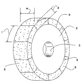
Fig. 1 is a perspective view of a segmented abrasive grinding wheel according
to this
invention.
This invention basically involves the discovery that abrasive tools with
conventional
abrasive grain can achieve the grinding performance of superabrasive-bearing
tools when
operated at ultra high tangential contact speed. The term "tangential contact
speed"
means the relative rate of motion in the direction tangential to the grinding
action
between the abrasive tool and the work piece. For example, the tangential
contact speed
of a continuous abrasive band saw blade cutting a stationazy block of work
would be the
linear speed of the blade in the direction of cut. Similarly, the tangential
contact speed of
an oscillating saw blade cutting a motionless block would be the linear speed
of the blade
in the direction of oscillation, observing that the blade speed necessarily
decelerates to
3o zero and re-accelerates instantaneously at the end of each stroke as the
blade reverses
direction.
3
CA 02463163 2004-04-23
For an abrasive wheel, the tangential contact speed is the linear speed of the
cutting
surface which is usually at the rotating wheel periphery. Tangential contact
speed takes
.. ~,
into account movement of the workpiece relative to the cutting blade. Thus-
t~e~ ; '
longitudinal feed movement of the surface of a work piece past a fixed
position,,,rotating
..
abrasive wheel contributes to the tangential contact speed. However, the tool
speed
contribution of the ultra high tangential contact speed abrasive tools
according to this
invention is generally disproportionately large compared to the longitudinal
movement
element. Normally, the longitudinal movement can be neglected: That'is, the
tangential
contact speed of an ultra high rotation speed abrasive wheel in most practical
situations is
effectively edual to the wheel cutting surface speed due to rotation. For
example, the
tangential contact speed of a 30 cm diameter wheel rotating at about 9,550
rev./min. is
150 m/s. The longitudinal feed movement of a work piece past this wheel
typically is less
than 1 m/s.
According to the present invention, superior grinding performance from
conventional
abrasives is obtained at tangential contact speed above about 125 m/s. The
upper speef
limit is not critical from a grinding performance standpoint. Generally, the
higher the
speed the better grinding performance that is 'obtained. However, practical
considerations
such as the burst strength of the tool and excessive heat build-up become
significant as
speed increases. Based on the limitations of presently available materials of
constrttetion,
2o tangential contact speed preferably should be in the range of about 150-200
m/s.
The navel method can be applied to any type of abrasive tool, such as drill
bits and
rotary saw blades, in addition to the tool types already mentioned. Manual
power
generally cannot sustain the ultra high tangential contact speed that
engenders superior
grinding performance. For most practical applications, the tool and/or the
work piece
z5 should be power driven, and accordingly, should be structurally strong
enough to
withstand the stress of automated operation. Hence, it is contemplated that
preferred
tools for practicing this invention should have an abrasive segment supported
by a
reinforced core.
The tool should be strong; durable and dimensionally stable in order to
withstand the
30 potentially destructive forces generated by high speed operation. The core
should have a
high core strength parameter, which is especially important for grinding
wheels operated
at very high angular velocity to achieve tangential contact speed above 125
m/s. The
CA 02463163 2004-04-23 /
minimum core strength parameter. preferred for the core for use in this
invention should
be about bOM Pa-cm3lg . The core strength parameter is defined as the'ratio of
core
...
material tensile strength divided by core material density. The tensile
strength of a
a.
material is the minimum force applied in tension for which strain of the
material increases
vvithout further increase of force. For example, ANST 4140 steel hardenedao
above about
,,
240 (Brinell scale) has a tensile strength in excess of 700 MPa. Density of
this steel is
about 7.8 g/em3. Thus, its core strength parameter is greater than about 90
MPa-cm3/g.
Similarly, certain aluminum alloys, for example, Al 2024, Al 7075 and AI 7178,
that are
heat treatable to Brinell hardness above about 100 have tensile strengths
higher than
~ about 300 MPa. Such aluminum alloys have low density of about 2:7 g/crn3 and
thus
exhibit a core strength parameter of more than 110 MPa-cm3/g. Titanium alloys
are also
suitable for use.
The core material also should be ductile, thermally stable at temperatures
reached in
the grinding zone, resistant to chemical reaction with coolants and lubricants
used in
grinding and resistant to wear by erosion due to motion of cutting debris in
the grinding
zone. Although some alumina and other ceramics yield at higher than 60 MPa-
cm3/g,
they generally are brittle and fail structurally as a core in high speed
grinding due to
fracture. I-ience, ceramics are not recommended for a high speed grinding tool
core.
Metal, especially hardened, tool quality steel, is preferred.
2o Preferably, the abrasive segment of the grinding wheel for use with the
present
invention is a segmented or continuous rim mounted on a core. A segmented
abrasive
rim is~ shown in Fig. 1. The core 2 has a central bore 3 for mounting the
wheel to an arbor
of a power.drive, not shown. The abrasive rim of the wheel comprises
conventional
abrasive grains 4 embedded in uniform concentration in a matrix of a bond 5. ~
A plurality
of abrasive segments $ make up the abrasive rim. Although the illustrated
embodiment
shows ten segme~its, the number of segments is not critical..
Broadly described, an individual abrasive segment has a truncated, rectangular
ring
shape characterized by a length, l, a width, w, and a depth, d: The wheel can
be
fabricated by first forming individual segments of preselected dimension an~fi
then
attaching the pre-formed segments to the circumference 9 of the core with an
appropriate
adhesive. Another preferred fabrication method involves forming segment
precursor
s
CA 02463163 2004-04-23
units of a mixture of abrasive grain W d bond composition around the core and
applying
heat and pressure to create and attach the segments, ih situ. ' ~ '
The embodiment of a grinding wheel shown in Fig. 1 is considered
represent~ti've of
._
wheels which may be operated successfully according to the present inven~iQn,
arid .
s should not be viewed as limiting., The numerous geometric variations for
segmented
grinding wheels deemed suitable include cup-shaped wheels, wheels with
apertures
through the core andlor between consecutive segments, and wheels with abrasive
segments of different width than the core. Apertures are sometimes used: to
provide paths
to conduct coolant to the grinding zone and to route cutting debris away from
the zone. A
1o wider segment han the core width is occasionally employed to protect the
core structure
from erosion through contact with swarf material as the wheel radially
penetrates the
work piece.
A basic defining criterion of any abrasive is that the abrasive substance be
harder
than the substance to be ground. Subject to this limitation, the conventional
abrasive of
15 this invention can be any abrasive other than a superabrasive as recognized
in the
grinding art. Thus conventional abrasive can include an extremely wide variety
of
materials, depending upon the hardness of the work piece in any particular
grinding
application. The conventional abrasive of this invention thus can include
moderately
hard, usually inorganic mineral compositions, such as corundum, emery; flint,
garnet,
2o pumice, alumina, and silica, and can encompass even very hard metal alloys
such as
carbides of tungsten, silicon, and molybdenum as well as various mixtures of
more than
.one such material to name just a few examples. Preferred conventional
abrasives include
aluminum.oxide (e.g.., fused alumina and sintered alumina, including seeded
and
unseeded sol gel sintered alumina), ilicon oxide, iron oxide, molybdenum
oxide,
25 vanadium oxide, tungsten carbide, silicon carbide, and mixtures of some or
all of them.
SoI gel alumina is a preferred conventional abrasive grain suitable for use in
the
present invention. "Sol gel alumina" means sintered sol-gel alumina in which
crystals of
alpha alumina are of a basically uniform size which is generally srnalier than
about 10
Vim, and more preferably less than about 5 ~,m, and most preferably less than
about 1 pm
3o in diameter. The sol gel alumina grain useful herein may be produced by a
seeded or an
unseeded sol gei process.
6
CA 02463163 2004-04-23
Sol-gel alumina abrasives are:conventionally produced by drying a soI or
gel.of an
alpha alumina precursor which'is usually but not essentially, boehmiteforming
the dried
gel info particles of the desired size and shape; then firing the pieces to a
temperature
sufficiently high to convert them to the alpha alumina form. The alpha
alu~nina ,gel can
be sintered to adjust porosity and the particles xnay be further broken,
screened~and sized
.;
to form polycrystalline grains of alpha alumina microcrystais. Simple sol-gel
processes
for making grain suitable for use in accordance with the present invention are
described,
for example, in U.S. Patent Nos. 4,314,827; 4,518,397 and 5,132;789; ahd
British Patent
. Application 2,099,012 , l
to In one form of sol-gel process, the alpha alurnina precursor is "seeded"
with a material
having the same crystal structure as, and lattice parameters as close as
possible to, those
of alpha alumina itself. The amount of seed material should not exceed about
10 weight
of the hydrated alumina. and there is normally no benefit to amounts in excess
.of about
. 5 weight %. If the seed is adequately fine (a surface area of about 60 mx
per gram or
more), preferably amounts of from about 0.5 to 10 weight %; more preferably
about 1 to 5
weight %, may be used. The seeds may also be added in the form of a precursor
which
converts to the active seed form at a temperature below that at which alpha
alumina is
formed. The function of the seed is to cause the transformatidn to the alpha
form to occur
uniformly throughout the precursor at a much lower temperature than is needed
in the
absence of the seed. This process produces a microcrystalline structure in
which the
individual crystals of alpha alumina are very uniform in size and are
preferably all sub-
micron in diameter. Suitable seeds include alpha alumina itself but also other
compounds
such as alpha ferric oxide, chromium suboxide, nickel, titanate and a
plurality of other .
compounds that have lattice parameters sufficiently similar to those of alpha
alumina to
be effective to cause the generation of alpha alumina from a precursor at a
temperature .
below that at which the conversion normally~occurs in the absence of such
seed.
Examples of sol gel processes for making abrasive grain suitable for use in
the
invention include, but are not limited to, those described in U.S. Patent Nos.
4,623,364;
4,744,802; 4;788,167; 4,881,971; 4,954,462; 4,964,883; 5,192,339; 5,2I5,551;
5,219,806; and 5,453,104. l
Sol gel, alumina abrasive~grains can be of many shapes, such as blocky and
f larrientary grains. Filamentary grains, occasionally referred to herein as
elongated or
7
CA 02463163 2004-04-23
"TG" have a high aspect ratio defined as the quotient ofa long characteristic
dimension
divided by an appreciably smaller short characteristic dimension. Theraspect
ratio af~
filarrientary seeded sol-gel alumina particles'in the mixture is at least
about 3:1, and
preferably at least about 4: 1. Such filamentary seeded sol-gel alumina grams
cry'
disclosed in U.S. Patents Nos. 5,194,072 and 5,201,916.
Blocky sol gel alumina grains, occasionally referred to herein as "SG"
material, generally have a granular appearance and have an aspect ratio of
about 1:1_
Particular preference is given to use of an abrasive grain comprising a
mixture of blocky
and filamentary soI-gel alumina grains. In the binary mixture, preferably
about 40-60
wt% of the particles is elongated and a complementary amount is blocky, and
more
preferably, elongated and blocky particles are about equal weight fractions.
Many modif cations of sintered sol gel alumina abrasive grain have been
reported.
All polycrystalline abrasive grain within the class is defined by the grain
comprising at
least 60% alpha aluminum~crystals having a density of at least about 95% of
theoretical
~ density, crystal size less than about 10 urn, and preferably uniform
microcrystals less than
I ~m or uniform crystals about 1-5 ~Cm, and a "Vickers hardness of greater
than about 16
GPa, preferably 18 GPa at 500 grams are suitable for use in this invention.
Tn.making unseeded sol gel alumina grain, modifiers. are often used to
influence
crystal size and other material properties. Typical modifiers may include up
to 15 wt% of
spinel, mullite, manganese dioxide, titanic, magnesia, rare earth metal oxide,
zirconia or
zirconia precursor (which can be added in larger amounts, e.g., about 40 wt%
or more).
The modifier is included in the initial sot as disclosed in the above-
mentioned U.S.
Patents Nos. 4,314,827, 5,192,339 and 5;215,551. Further modifications involve
inclusion of various amounts of modifiers, for example; yttria, oxides~of rare
earth metals,
such as lanthanum, praseodymium, neodymium, samarium, gadolinium; erbium, ,
ytterbium, dysprosium and cerium, transition metal oxides and lithium oxide as
disclosed
in U.S. Patents Nos. 5,527,369, and 5,593, 468. 'these
modifiers are often included to alter such properties as fracture toughness,
hardness,
friability, fracture mechanics, or drying behavior.
In another aspect of this invention, it is contemplated to use a combination
abrasive
material which comprises a conventional abrasive component and a superabrasive
component: The grinding capability enhancement obtained by ultra high speed
grinding
8
CA 02463163 2004-04-23
is of such magnitude that a substantial portion of superabrasive grain can be
replaced by
conventional abrasive without sacrifice of performance. The present invention
thus
~,,
provides a techninue for obtaining from ~n abrasive segment having a minor.
fraction (<
50%) of superabrasive grain, the grinding rate and tool life close to that
expected,from
tools of I 00% superabrasive. Preferably, the conventional abrasive component.
,,
constitutes a major fraction ( > 50%) of the total abrasive in the abrasive
segment , and
more preferably, at least about 80 % of total abrasive. The conventional
abrasive and
superabrasive components can be mixed uniformly throughout the abrasive
segment .
They also can be segregated in distinct regions of the abrasive segment ~ of
combinations
to of mixed and segregated regions can be incorporated in a single tool.
The abrasive segment should be constructed to provide structural integrity
able to
withstand rupture and disintegration when the tool is operated at ultra high
tangential
contact speed, f: e:, above I25 mls. Accordingly, the abrasive segment should
exhibit a
minimum rim strength parameter def ned as the tensile strength divided by the
density of
the conventional abrasive. In view of the fact that the stresses operating on
the abrasive
segment of a grinding wheel are reduced at the periphery relative to the
center of the
wheel, the minimum rim strength parameter of the abrasive segment for
use according to this invention can be less than the core strength parameter
of the core.
Preferably, the rim strength parameter should be at least about 10 l~IPa-
cm3/g.
2o The composition for the bond material can be any of the general types
common in the
art. For example, glass or vitrified, resinoid, or metal may be used
effectively, as well as
hybrid bond material such as metal filled resinoid bond material and resin
impregnated ,
vitrified bond. A: vitrified bond is preferred.
Resinoid bond can be used provided, of course, that.the bond has sufficient
strength
~ and heat resistance. Any of the well-known cross linked polymers such as
phenol-
aldehyde, melamine-aldehyde, urea-aldehyde, polyester, polyimide, and 'epoxy
polymers
can be employed. Resinoid bond can include f hers such as cryolite, iron
sulfide; calcium
fluoride, zinc fluoride, ammonium chloride, copolymers of vinyl chloride and
vinylidene
chloride, polytetrafluoroethylene; potassium fluoroborate, potassium sulfate,
zinc
3o chloride, kyanite, mullite, graphite, molybdenum sulfide, and mixtures of
these.
Any of the well-known vitrified bonds may be used. Fox conventional abrasive
wheels containing sol gel alumina grain, it has been found important to use
vitrified
9
CA 02463163 2004-04-23
bonds that can be fired at relatively low temperatures: In context of firing
of vitrified
bonds, low temperature firing is understood to be no greater than about' 1
I00°C. Firing
. - -~.
temperatures are preferably less than about 1000°C. Vitrified bonds
gen~erall~ comprise
fused metal oxides such as oxides of silicon, aluminum, iron, titanium,
eal~ium; .'~'
magnesium, sodium, potassium, lithium, boron, manganese and phosphorous and
typically incorporate mixtures of oxides of these metals. Representative metal
oxides for
inclusion in a vitrified bond are SiOa, A1z03, Fe203, Ti02, CaO, MgO, NazO,
KZO, Li20,
8203, lVIn02, and P205. The vitrified bond can be effected by employing~the
metal oxide
components in fine particulate form. If multiple metal oxides are included,
the particles
should be mixed to uniformity. Advantage may result by making a frit from the
raw
components of the vitrified bond composition, grinding the frit to a powder
and using the
frit to bond the abrasive grain. A frit can be obtained by prefiring the
composition raw
precursors of the metal oxide components at a temperature and for a duration
effective to
form a homogeneous glass. .Temperatures in the range of about 1100°C-
1800°C are
typical.
The abrasive segment of the wheel can be formed by blending fine particles of
abrasive grain and bond composition components to form a dry mixture. Blending
is
continued until a uniform concentration of abrasive and bond is obtained.
Alternatively; a
wet blend can be formed by incorporating an optional, fugitive liquid vehicle
with the dry
particles. The term "fugitive" means that the liquid vehicle leaves .the blend
when the
bond is formed by curing
as explained below. The vehicle is a typically moderate to high-boiling,
organic liquid
capable of mixing with the dry particle components to form a viscous paste.
The liquid
facilitates preparation of a uniform bond and abrasive network and further
helps to
dispense the bond and abrasive composition during the segment-forming process.
Examples of fugitive liquid vehicle materials suitable for use with this
invention include -
water, animal glue, aliphatic alcohols; glycols, oligomeric glycols, ethers
and esters of
such glycols and oligomeric glycols and waxy or oily high molecular weight
petroleum
fractions such as, mineral oil and petrolatum. Representative alcohols include
isopropanol and n-butanol. Representative glycols and oligomeric glycols
include
ethylene glycol, propylene glycol, I,4-butanediol, diethylene glycol, and
diethylene glycol
monobutylether.
to
CA 02463163 2004-04-23
Porosity forming agents and other additives optionally can be added to the
abrasive
segment mixture. Representative porosity forming agents and other additives
include
~,..
hollow ceramic spheres (e.g., bubble alumina) and particles of graphite,
silver; nickel,
copper, potassium sulfate, cryolite, kyanite, hollow glass beads, ground
walnut shells,
beads of plastic material or organic compounds (e.g., polytetrafluoroeth~lye);
and
foamed glass particles. Porosity forming agents are especially useful in
vitreous bond
compositions and about 30-60 vol. % porosity forming agent is preferred. A
preferred
vitreous bond abrasive segment has the composition of about 26 vol. % blocky
sol gel
. alumina particles, about 2b vol. % elongated sol gel alumina filamentary
particles, about
1o 10-i3 vol. % fused metal oxide rnixture.and an effective amount of porosity
fon~ning
agents to yield about 35-38 vol. % porosity. Open cell porous structure is
preferred.
The mixture can be cold-compacted at low temperature and high pressure in a
preselected mold to form a "green" segment precursor. The term "green" is used
to mean
that the materials have.strength to maintain shape during the next following
intermediate
1s process steps but do not have sufficient strength to maintain shape
permanently. The
green precursors can be cured in a variety of ways to achieve full strength
and permanent
shape. The curing method and operating conditions therefor depend upon the
type of
bond materials being used. For example, resinoid bonds can be cured by
chemical
reaction in the presence of chemical catalysts, additional reactants;
radiation and the like.
2o Vitreous and metal bonded segments are often formed by faring at elevated
temperature
while compressing the precursor. The vitreous and metal bond composition
components
fuse at the high temperatures then are cooled to embrace the abrasive
particles in a strong,
rigid uniform matrix.
After the abrasive segments are fabricated they can be attached to the core by
various
25 methods known in the art, such as brazing, laser welding, mechanical
attachment or
gluing with an adhesive or a cement. Great preference is given to cementing
the abrasive
segments to the core. Naturally, the adhesive should be very strong to
withstand the
destructive force which is likely to exist during operation, especially in
xotary tools, such
as grinding wheels. Two-part epoxy resin and "hardener" cement is preferred.
3o This invention is now illustrated by examples of certain representative
embodiments
thereof, wherein all parts, proportions and percentages are by weight unless
otherwise
I1
CA 02463163 2004-04-23
indicated. All units of weight and measure not originally obtained in SI units
have been
converted to SI units.
Example 1 ..~ '
A 1693 gram abrasive grain mixture of 50% SG grain and SO% TG grain,
eachhaving
12S ~m grit size (U.S. No. 120 sievej, obtained from Norton Company,,
V~'orcester, MA,
were blended in a motorized mixer for 5-IO minutes with 210 grams of a mixture
of
vitrified bond components. The bond is described in U.S.-A-5,40I,284 and it
includes a
major fraction of SiG2, and a minor fraction of each of A1203, KzO, NazQ, Li20
and B203.
Animal glue and water in amount of 48 g was included in the composition to
provide a
to uniformly concentrated wetted powder mixture. The mixture was placed into
molds to
produce curvilinear segments of the type shown in Fig. 1. Dimensions of the
segments
were 25 mm long, 10 mm wide and 10 mm deep. The molds were cold pressed at 7-
14
MPa for about 20-30 seconds to produce "green" segment precursors. The
precursors
were fired in an air oven at 1000 °C for 8 hours to obtain the
completed segments. After
firing, the curvature of the segments was well defined and no stumpage was
evident.
Twenty-five segments were mounted about the complete circumference of each of
three 38.0 cm diameter circular high strength, low alloying steel grinding
wheel cores to
provide nominally 40 cm diameter wheels. The central bore diameter ofthese
wheels
was 12.7 cm. The rim of the steel core was sandblasted to obtain a degree of
roughness
2o prior to attachment of the segments. Technodyne~ HT-I8 (Taoka Chemicals,
Japans
epoxy resin and its modified amine hardener was prepared by hand mixing in the
ratio of
100 parts resin to I9 parts hardener. Fine silica powder filler was added at a
ratio of 3.5
parts per 100 parts resin to increase viscosity. The thickened epoxy cement
was then
applied to the ends and bottom of segments which were positioned on the core
substantially as shown in Fig. 1. Roughening the core improved the effective
interfacial
area for adhesion of the epoxy. The epoxy cement was allowed to cure at room
temperature foil 24 hours followed by 48 hours at 60°C. Because the
viscosity had been
increased, drainage of the epoxy during curing was minimized.
Burst speed testing was done by spin test at acceleration of 45 rev./min. per
s. Even
though the abrasive segment depth was about 2-3 times that of a typical
superabrasive
wheel, the test wheels demonstrated burst rating equivalent to 271, 275 and
280 m/s
12
CA 02463163 2004-04-23
tangential contact speeds. ~ Thus the test wheel would qualify for operation
under
currently
-,..
applicable safety standards at 200 m/s and 180 m/s tangential contact speed
iri Europe and
. the United States, respectively. ~ . ' ;
Example 2 ;.
Three wheels were prepared as in Example 1 except that the core was ANSI 7178
alununum alloy instead of steel. Burst speeds were 306, 311 and 3I 1 m/s.
Example 3 ,
A grinding wheel was prepared as described in Exan3ple 2 except that Redux~
420
to epoxy and hardener (Ciba-Geigy Polymer Division, France) was used. The
adhesive was
cured for 4 h at 60°C. durst speed was 346 m/s.
Example 4
A grinding wheel was fabricated as in Example 1 except that the depth of the
abrasive
segments was increased to 25 mm. Speed at burst was measured in the range of
246-264
m/s which would qualify for operation at tangential contact speed of up to 180
m/s and up
to 160 m/s in Europe and the United States, respectively.
Examples 5-19
Experimental grinding wheels 5-19 (400 mm diameter, 10 mm thickness with 127
mm diameter bore), each having 25 abrasive segments of 10 mm depth, were
prepared
2o substantially as described in Example 1. The type of abrasive grain used in
each wheel is
shown in Table I. The CBN grain had a grit size of 125 p.m. The conventional
grains
used in examples 5, 7, 12-17 and 19 were 250 p,m grit,size (SG) or 180 ~m grit
size (TG).
All other conventional grain used in these examples had a grit size of 125.
um. Abrasive
grain constituted about 52% of the abrasive segment volume., Each wheels was
proof
2s tested at rotation speed equal to 230 mls tangential contact speed and no
segment
breakageor steel core yield was observed.
The wheel of Example 6 was tested by plunge grinding a 6.4 mm width of ANSI
52100 or UNS 652986 bearing steel of 60 Rockwell C hardness to a depth of 5.18
mm.
The wheel was operated at a tangential contact speeds of 60 mlsec, 90 rn/sec,
I20 mlsec
30 and 150 n~/sec. A Studer CNC S-40 grinding machine with 60 wt% oil, aqueous
coolant
was used. The maximum power rating of the Studer grinder was 9 kW, thus at the
higher
13
CA 02463163 2004-04-23
speed and higher metal removal rate the wheel pushed the machine. neat and
beyond its
design performance specifications.
~: ..
Results are shown in Table 1. At all metal removal rates, wheel 6 demonstrated
significantly better G-ratio, with acceptable power draw, at 150 m/sec
relative to:~120
m/sec. At the two highest metal removal rates, wheel 6's performance way
adversely
,~ -
affected by the grinding machine limitations and even better performance is
~predieted for
the wheel on a machine designed to operate at a higher rate. At alI wheel
speeds and aII
metal removal rates little variation in the surface finish was observed arid
the quality of
the surface finish was acceptable. Wheel 6 containing conventional sol gel
alumina
to abrasive was easily dressed by a single row, six diamond point stationary
dresser blade
during this test. .
Table 1 Grinding_Perforrnance of Wheel 6
Speed 150 m/sec 120 m/sec ~ 90 m/sec , 60 mlsec
Metal Removal G-ratio Power G-ratio Power G-ratio Power G-ratio Power
Rate mm3/s~mm W/mm W/mm ~ W/mm W7mm
3.2 240.1 1140.8 74.5 772.8 88.9 496.8 58.2 346.5
6.4 157..0 1269.6 68.5 858.7 68.1 574.4 54.2 435.5
9.6 136.6 1159.2 54.7 ~ 895.5 63.2 619.5 49.9 484.5
12.8 139.3 1288.0 53.8 870.9 61.1 650.1 49.5 548.9
16.0 78.2 1508.8 47.8 950.7 52.8 748.3 48.6 628.7
19.3 nla* n/a* 40.2 1030.4 49.8 809.6 47.2 6?4.7
* The grinding machine had insufficient power to operate at this IvIRR and
vYheel speed.
Another grinding test was conducted under the same conditions (except a 3.2 mm
width of cut was made on the workpiece) in order to compare the grinding
performance
of wheels of Examples 5-19. In this test, commercially acceptable G-ratios,
power draw
and surface f nish quality were observed for all wheels. Results are shown in
Table 2.
Attempts to grind a 3.2 mm width of cut on the workpiece under these
conditions at a
150 m/sec wheel speed using a comrrzercial vitrified bonded CBN~control wheel
resulted
in wheel breakage. This made it impossible to directly compare superabrasive
wheels to
the wheels of the invention at the speed of 150 m/sec. These commercial CBN
wheels
(same shape as tile experimental wheels, with abrasive segments 5 mm in depth,
14
CA 02463163 2004-04-23
containing 36 vol: % 125 ~,m grit CBN and 20 vol. % bond) could only be tested
at a
tangential contaet speed of 120 m/sec. The CBN wheel displayed a maximum
rl~etal
-,.
removal rate of 122 mm3/s.mm at 120 m/sec. . . ~ ;
Examples 5 and 6 contain no superabrasive grain. The grain used was ~.
blend~of
,.
conventional abrasive grains of sol gel alumina. These wheels were able to
deliver a
maximum metal removal rate of 148 mm3/s.mm, about 21 % greater than the
commercial
CBN wheels which could only be operated at 120 m/sec. All of the conventional
abrasive
and conventional abrasive/CBN wheels were easily dressed by a single'row, six
diamond
point stationary dresser blade. In contrast, the commercial CBN wheels
.required dressing
by a rotary dresser. The ~superabrasive wheels also produced significant
amounts of
chipping and loading which was not seen in the wheels with conventional
abrasives.
The diff culties in dressing superabrasive wheels to open the face of the
wheel and to
correct the dimension of the wheel (true the wheel; typically before initial
use and during
grinding operations, as needed) are well-known to the industry and a serious
deterrent to
use of superabrasive wheels, particularly CBN wheels, in spite of their
demonstrated
superiority in many high speed grinding operations. None of these difficulties
were
observed with the wheels of the invention.
Based on these data, maximum metal removal rates, G-ratios and other grinding
performance parameters of the wheels of the invention are projected to be
equivalent to
2o those of commercial CBN wheels when operated at the higher speeds (i.e., at
least 125
m/sec) designated for operating the wheels of the invention. Although the CBN
wheels
are observed to have higher G-ratios than the wheels of the.invention when
operated at
speeds of 120 m/sec or less, the ease of dressing observed for the wheels of
the invention,
in combination with significant abrasive grain cost savings, permit commercial
operations
to utilize wheels having deeper abrasive segments and containing more abrasive
grain.
The greater segment depth possible with the wheels of the invention will
compensate for
observed lower G-ratios at lower metal removal rates to yield results
equivalent to
commercial superabrasive wheels over the lives of both types of wheels.
Test results for the wheels of Examples 7-19 demonstrate that operation at
tangential
3o contact speed above 125 m/s according to the present invention offers the
ability to
substantially.replace or dilute superabrasive with much less costly
conventional abrasive
grain and obtain acceptable grinding performance to replace a superabrasive
tools.
CA 02463163 2004-04-23
Example 20 ~ ' ,
A wheel containing an unneeded sol gel alumina abrasive grain (32'1 grain made
by
w y..
3M Corporation, Minneapolis, MN) was prepared in the same manner as Exainpl~
6,
except that no TG alumina grain was used. In a grinding test under the
sat~e..con~ditions
s used above (grinding a 3.2 mm width cut on the workpiece), the unseeded'sol
gel, alumina
grain wheel displayed grinding performance at least equivalent to wheels 6 at
120 m/sec
and 150 mlsec, and compared favorably to .the commercial CBN wheel at I20
m/sec.
Thus, unseeded,, as weh as seeded and filamentary, polycrystalline sintered
sol gel alpha-
. alumina grain is preferred for use in the wheels of the invention. ~ w
Although specific forms of the invention have been selected for illustration
in the
drawings and examples, and the preceding description is drawn in specific
terns for the
purpose of describing these forms of the invention, this description is not
intended to
limit the scope of the invention which is defined in the claims:
Table Grinding
2 Performance
at 150
m/sec
Abrasive AbrasiveBond Max. MetalGrindingAverage No. CutsDressing
Wheel vat.%-(vol.%)Removal Power G-Ratio for G-RatioOperation
Rate
Type' (mm3/smm) (kW) (mm'Imm3)
Ex.S 26-TG,10 148 II.S 399 9 Stationary
26-SG Diamond
Blade/easy
Ex.6 26-TG 13 148 12 452 9 ~ "
26-SG
Ex.7 26-TG 10 148 9 307 9 Stationary
16-SG Diamond
10-CBN Blade/OK
Ex.8 26-TG IO i61 10 332 3
16-SG
10-CBN
Ex.9 26-TG 13 148 8 228 9 "
I6-SG
10-CBN
Ex.lO 26-TG 13 168 10 457 3 "
16-SG
10-CBN
Ex. 1 i 26-TG 13 174 9.7 4S7 3 "
16
CA 02463163 2004-04-23
16-SG
10-CBN
Ex. I2 26-TG 13 148 9 362 9 w
16-SG
,. .
10-CBN
'
Ex. 13 TG 13 161 9 443 3 ,
26 - "
16-SG
10-CBN
Ex. l4 26-TG 13 168 11.5 443 3.. "
16-SG
10-CBN
Ex. IS 26-TG 8 148 7.6 166 3 . "
At high
16-SG
MRR corner
10-CBN
breakdown
Ex. l6 26-TG 8 168 7.6 166 3 "
16-SG
10-CBN
Ex. l7 26-TG 8 187 9.1 221 3 "
16-SG
10-CBN
Ex.lB 26-TG 9 103 6.9 443 3 "
16-SG
10-CBN
Ex. l9 26-TG 9 122 S.8 -
16-SG
10-CBN
Control 36--CBN 20 122 8.2 wheel broke- ~ Rotary Dresser
At high MRR
wheel face loads
& chips
17