Note: Descriptions are shown in the official language in which they were submitted.
CA 02463237 2004-04-07
WO 03/039762 PCT/SG02/00236
A PAINT ROLLER
Field of the Invention
(0001] The present invention relates to apparatus for applying fluids over
surfaces. In particular, the present invention relates to a paint roller for
storing and applying paint.
Background of the Invention
[0002] Paint rollers for applying paint onto surfaces are known. Typically,
such paint rollers have paint-absorbing surfaces that are dipped into paint
containers and then rolled over surfaces that are to be painted. For example,
US Patent No. 6,098,240, issued to Taylor, describes a roller paint applicator
with a cylindrical body and that is secured to an applicator holder for
rotation
around a spindle using an end cap. However, rotation of the paint roller
described in US Patent No. 6,098,240 is a problem when excessive force is
applied to the applicator holder. Such a force can dent the paint applicator
towards the spindle and undesirably restrict rotation of the spindle.
[0003] Another type of paint roller is described in US Patent No. 6,098,240
in which internal storage or container space is provided to store paint. The
paint is then transferred from the internal storage or container space through
permeable members onto surfaces. An example of such an improvement to
paint rollers is disclosed in US Patent No. 3,588,264, issued to Mallindine
and that describes a container-type paint roller with a roller assembly. The
roller assembly is rolled along a surface by means of a forked handle that is
coupled to journals of end-closure members disposed at opposite ends of the
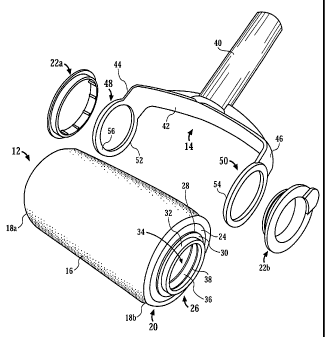
roller assembly.
(0004] However, rotation of the roller assembly of US Patent No. 3,588,26
can be a problem as the end-closure members contacts the entire surface of
CA 02463237 2004-04-07
WO 03/039762 PCT/SG02/00236
2
sides of the forked handle. Consequently, frictional resistance between the
sides and the end-closure members impedes the rotation of the roller
assembly to some extent. Furthermore, any unevenness of the surface of the
end closure members also impedes the rotation. Such unevenness is difficult
to avoid or eliminate in mass production of the end-closure members or the
forked handle.
[0005] Therefore, a need clearly exists for a container-type paint roller that
enables easier rotation of a paint applicator by reducing frictional
resistance
between rotating elements. Such a container-type paint roller should have
covers that secure tightly to the paint applicator or an applicator holder
without, or at least alleviating, undesired dislodging of such covers during
use.
Brief Summary of the Invention
[0006] The present invention seeks to provide a paint roller having a paint
applicator and two holder mounts respectively associated with two opposite
ends of the paint applicator, and an applicator holder for the paint roller.
[0007] Accordingly, in one aspect, the present invention provides a paint
roller comprising:
a paint applicator having a cylindrical outer surface and two
opposite ends; and
two holder mounts, respectively associated with the two opposite
ends, each of the holder mounts having:
a base surface;
a journal, protruding from the base surface in a direction
away from the paint applicator;
and
one or more holder abutments, protruding from the base
surface in the direction.
CA 02463237 2004-04-07
WO 03/039762 PCT/SG02/00236
3
[0008] In another aspect, the present invention provides a paint roller
comprising:
a paint applicator having a cylindrical outer surface and two
opposite ends;
two holder mounts, respectively associated with the two opposite
ends, each of the holder mounts having:
a base surface;
and
a journal, protruding from the base surface in a direction
away from the paint applicator;
and
an applicator holder having:
a handle;
and
a fork having opposite sides, each of the opposite sides
having:
a journal engagement portion;
and
a plurality of applicator abutments, protruding from
a surface of the journal engagement portion in a
direction towards the paint applicator.
[0009] In a further aspect, the present invention provides an applicator
holder
for a paint roller with at least one journal, the applicator holder
comprising:
a handle;
and
a fork having opposite sides, each of the opposite sides having:
a journal engagement portion;
and
a plurality of applicator abutments, protruding from a
CA 02463237 2004-04-07
WO 03/039762 PCT/SG02/00236
4
surface of the journal engagement portion in a direction
towards the at least one journal.
Brief Description of the Drawings
[0010] A preferred embodiment and alternate embodiments of the present
invention are described, by way of example, with reference to the drawings of
which:
[0011] FIG. 1 is a perspective view of a paint roller having a paint
applicator
and an applicator holder in accordance with the preferred embodiment of the
invention;
[0012] FIG. 2 is an exploded view of the paint roller of FIG. l;
[0013] FIG. 3 is a side view of a holder mount associated with one end of the
paint applicator of FIG. l;
[0014] FIG. 4 is a side view of a cover for one end of the paint applicator of
FIG. 1;
[0015] FIG. 5 is a plan view of a holder mount in accordance with one
alternate embodiment of the invention;
[0016] FIG. 6 is a side view of an end portion of the holder mount of FIG. 5;
[0017] FIG. 7 is an exploded view of the paint roller of FIG. 1 in accordance
with another alternate embodiment of the invention;
[0018] FIG. 8 is a plan view of a holder mount associated with one end of a
paint applicator of the paint roller of FIG. 7;
CA 02463237 2004-04-07
WO 03/039762 PCT/SG02/00236
[0019] FIG. 9 is a side view of the holder mount of FIG. 8;
[0020] FIG. 10 is an exploded view of the paint roller of FIG. 1 in
accordance with yet another alternate embodiment of the invention;
5
[0021] FIG. 11 is a side view of a holder mount associated with one end of a
paint applicator of the paint roller of FIG. 10;
[0022] FIG. 12 is a plan view of a journal engagement portion of an
applicator holder for the paint roller of FIG. 10; and
[0023] FIG. 13 is a side view of the journal engagement portion of FIG. 12.
Detailed Description of the Drawings
[0024] A paint roller having a paint applicator and two holder mounts for
coupling to an applicator holder in accordance with a preferred embodiment
and alternate embodiments of the invention are described. In the following
description, details are provided to describe these embodiments. However, it
shall be apparent to one skilled in the art that the invention may be
practiced
without such details. Some of these details may not be described at length so
as not to obscure the invention.
[0025] There are many advantages of the embodiments of the invention. One
advantage of the embodiments is that frictional resistance between abutting
surfaces of the holder mounts and the applicator holder is reduced.
Consequently, the embodiments enable a more effective rotation of the paint
applicator when held by the applicator holder during use of the paint roller.
[0026] Another advantage of the embodiments of the invention is that ridges
of a cover and of one of the holder mounts enable a tight capping of the
holder mount. These ridges are formed on an inner wall of a channel or on an
CA 02463237 2004-04-07
WO 03/039762 PCT/SG02/00236
6
internal wall of a cylindrical protrusion forming the channel. Consequently,
paint is stored more securely within the paint applicator without, or at least
alleviating, accidental spills due to dislodging of the cover during use of
the
paint roller.
[0027] Referring now to FIG. 1, a perspective view of a paint roller 10 in
accordance with the preferred embodiment of the invention is illustrated. The
paint roller 10 comprises a paint applicator 12 and an applicator holder 14
for
holding the paint applicator 12. The paint applicator 12 has a cylindrical
outer
surface 16 and two opposite ends 18a,18b. The paint applicator 12 is
preferably made of a paint absorbent material such as, for example, foam or
sponge.
[0028] The paint roller 10 further comprises two holder mounts, respectively
associated with the two opposite ends 18a,18b. A holder mount 20, associated
with the opposite end 18b, is shown in the exploded view of the paint roller
10 in FIG. 2. Also shown in FIG. 2 are two covers 22a,22b for respectively
capping the two holder mounts.
[0029] The holder mount 20 has a base surface 24 and comprises a journal 26
that protrudes from the base surface 24 in a direction away from the paint
applicator 12. The journal 26 comprises a holder abutment 28 having a planar
abutment surface 30. The journal 26 further comprises a cylindrical
protrusion 32 forming a channel 34 through which paint is channeled for
storage within, or for removal from, a chamber (not shown) of the paint
applicator 12. In the preferred embodiment of the invention, the holder
abutment 28 forms a ring surrounding the cylindrical protrusion 32. An inner
wall 36 of the channel 34 has a circumferential ridge 38. For the journal 26,
the planar abutment surface 30 has a total area that is smaller than an axial
cross-section of the holder mount 20.
CA 02463237 2004-04-07
WO 03/039762 PCT/SG02/00236
7
[0030] The applicator holder 14 has a handle 40 and a fork 42 having
opposite sides 44,46. Each of the opposite sides 44,46 has, respectively, a
journal engagement portion 48,50. Each of the journal engagement portions
48,50 comprises, respectively, a loop 52,54. The loop 54 couples to the
cylindrical protrusion 32 at the opposite end 18b, and the loop 52 couples to
a
cylindrical protrusion (not shown) at the opposite end 18a, to enable rotation
of the paint applicator 12 during use. In coupling to the cylindrical
protrusion
32, each loop 52,54 encircles the cylindrical protrusion 32 at each of the
opposite ends 18a,18b.
[0031] The loop 54 has a mount abutment surface (not shown) with an area
larger than the total area of the planar abutment surface 30. The mount
abutment surface for the loop 54 is similar to a mount abutment surface 56
for the loop 52. Hence, contact area between the planar abutment surface 30
and the mount abutment surface of the loop 54 is, at most, the area of the
planar abutment surface 30. Consequently, only frictional resistance of
respective contact areas, and not the entire area of the mount abutment
surfaces of the loops 52,54, impedes rotation of the paint applicator 12 when
held by the applicator holder 14.
(0032] FIG. 3 is a side view of the holder mount 20 showing position of the
holder abutment 28 for the journal 26 relative to the base surface 24. The
planar abutment surface 30 is substantially aligned on a common plane 60. In
the preferred embodiment, the common plane 60 is planarly parallel to a base
plane 62 of the base surface 24 and spaced apart from the base plane 62 by
the thickness of the holder abutment 28.
(0033] Referring now to FIG. 4, a side view of the cover 22b for capping the
holder mount 20 is illustrated. The cover 22b comprises a cylindrical portion
64 having two perimeter ridges 66,68 and a flange ~70. The flange 70 extends
beyond a perimeter 72 of the cylindrical portion 64. The cover 22b further
CA 02463237 2004-04-07
WO 03/039762 PCT/SG02/00236
8
comprises a flange extension 74 to enable removal of the cover 22b to
thereby replenish paint within, or empty paint from, the chamber of the paint
applicator 12.
[0034] The two perimeter ridges 66,68 are engageable with the
circumferential ridge 38 of the inner wall 36 to enable a tight capping of the
holder mount 20 by the cover 22b. Specifically, the diameter of the
cylindrical portion 64 is made slightly larger than the diameter of the
channel
34 to provide a secure fitting. This secure fitting is enhanced by engagement
between the perimeter ridges 66,68 and the circumferential ridge 38 when
capping the holder mount 20. Hence, a force applied to cap the cover 22b
onto the holder mount 20 has to overcome abutting of the cylindrical portion
64 and the inner wall 36 of the channel 34 as well as abutting of the
perimeter
ridges 66,68 and the circumferential ridge 38.
[0035] FIG. 5 is plan view of a holder mount 100 in accordance with the
alternate embodiment of the invention. In the holder mount 100, a journal 102
comprises a cylindrical protrusion 104 extending from a base surface 106 of
the holder mount 100 and one or more holder abutments 108. The cylindrical
protrusion 104 forms a channel 110 through which paint is channeled for
storage within or removal from the paint applicator 12. FIG. 5 also shows the
area of the mount abutment surface of the loop 54 in dotted outline.
[0036] The holder abutment 108 corresponds to a plurality of arc-shaped
members. FIG. 5 shows four arc-shaped members 108a,108b,108c,108d
disposed around the cylindrical protrusion 104. Each of the four arc-shaped
members 108a,108b,108c,108d has a planar abutment surface
112a,112b,112c,112d. As illustrated, the mount abutment surface of the loop
54 has an area larger than total area of the planar abutment surfaces
112a,112b,112c,112d. Also, the total area of the planar abutment surfaces
CA 02463237 2004-04-07
WO 03/039762 PCT/SG02/00236
9
112a,112b,112c,112d is smaller than an axial cross-section of the holder
mount 100.
[0037] In FIG. 6, a side view of an end portion of the holder mount 100 from
a direction indicated by an arrow 114 shows the planar abutment surfaces
112a,112b,112d of, respectively, the arc-shaped members 108a,108b,108d.
The planar abutment surfaces 112a,112b,112d are substantially aligned to
each other on a common plane 116. Although not shown, the planar abutment
surface 112c is also similarly aligned. In this alternate embodiment, the
common plane 116 is planarly parallel to a base plane 118 of the base surface
106 and spaced apart from the base plane 118 by the thickness of the four
arc-shaped members 108a,108b,108c,108d.
[0038] Referring now to FIG. 7, an exploded view of the paint roller of FIG.
1 in accordance with another alternate embodiment of the invention is shown.
In this alternate embodiment, a holder mount 200 has a base surface 224 and
comprises a journal 226 that protrudes from the base surface 224 in a
direction 228 away from the paint applicator 12. The holder mount 200
comprises a plurality of holder abutments 230 that protrudes from the base
surface 224 in the direction 228.
[0039] The journal 226 comprises a cylindrical protrusion 232 forming a
channel 234 through which paint is channeled for storage within, or for
removal from, a chamber (not shown) of the paint applicator 12. In this
alternate embodiment of the invention, the plurality of holder abutments 230
surrounds the cylindrical protrusion 232. The cylindrical protrusion 232 has
an internal wall 236 with a channel ridge 238 formed thereat. In coupling to
the cylindrical protrusion 232, each of the loops 52,54 encircles the
cylindrical protrusion 232 at each of the opposite ends 18a,18b.
CA 02463237 2004-04-07
WO 03/039762 PCT/SG02/00236
[0040] Each of the loops 52,54 has a mount abutment surface. A mount
abutment surface 56 for the loop 52 is indicated. The mount abutment surface
(not shown) for the loop 54 is similar to the mount abutment surface 56 for
the loop 52.
5
[0041] The cover 22b in this alternate embodiment comprises a wall
engagement portion 260 for engaging the internal wall 236. The wall
engagement portion 260 has a cover ridge 262 for coacting with the channel
ridge 238. The cover 22b further comprises a flange 264 extending beyond a
10 perimeter of the wall engagement portion 260 and a flange extension 266.
The flange extension 266 enables removal of the cover 22b to thereby
replenish paint within, or empty paint from, the chamber of the paint
applicator 12 via the channel 234.
[0042] The remaining journal (not shown) that is associated with the holder
mount at the opposite end 18a does not have a channel. However, this
remaining journal can be modified to have such a channel as the journal 226.
Consequently, the cover 22a caps the journal (not shown) at the opposite end
18a to retain the loop 52 to the mount holder (not shown).
[0043] Coaction between the cover ridge 262 and the channel ridge 238
provides a snap fit that serves as an audible indication that the cover 22b
has
properly covered the opening of the channel 234. The coaction also enables a
tight capping of the holder mount 200 by the cover 22b. Specifically, the
diameter of the wall engagement portion 260 is made slightly larger than the
diameter of the channel 234 to provide a secure fitting when capping the
holder mount 200 with the cover 22b. Hence, a force applied to cap the cover
22b onto the holder mount 200 has to overcome abutting of the wall
engagement portion 260 and the channel 234 as well as abutting of the cover
ridge 262 and the channel ridge 238.
CA 02463237 2004-04-07
WO 03/039762 PCT/SG02/00236
11
[0044] FIG. 8 is a plan view of the holder mount 200 associated with the
opposite end 18b of the paint applicator 16 and looking into the channel 234
in a direction 268.
[0045] FIG. 9 is a side view of the holder mount 200 showing position of the
plurality of holder abutments 230 relative to the base surface 224 and the
cylindrical protrusion 232. The plurality of holder abutments 230 is
substantially aligned to provide an abutment plane 270. In the preferred
embodiment, the abutment plane 270 is planarly parallel to a base plane 272
provided by the base surface 224 and spaced apart from the base plane 272 by
the thickness of the holder abutments 230.
[0046] As the mount abutment surfaces of the loops 52,54 only contact
specific surface areas of the plurality of holder abutments 230 providing the
abutment plane 270, frictional resistance between the holder mounts at both
ends 18a,18b and the loops 52,54 is reduced. Consequently, rotation of the
paint applicator 12 when held by the applicator holder 14 is easier compared
with existing container-type paint rollers.
(0047] In the alternate embodiment as shown in FIG. 7, FIG. 8 and FIG. 9,
each of the plurality of holder abutments 230 is hemispherical. However, it is
to be noted that other shapes are also possible for the plurality of holder
abutments 230 to reduce contact areas and, hence, reduce frictional resistance
between the two holder mounts of the paint roller 10 and the loops 52,54. For
example, each of the plurality of holder abutments 230 can have a flat surface
that, collectively, are substantially aligned along the flat surface relative
to
each other to thereby provide the abutment plane 270. Otherwise, in the
absence of the plurality of holder abutments 230, there would be full surface
contact between the base surface 224 and the mount abutment surfaces of the
loops 52,54, which results in more frictional resistance.
CA 02463237 2004-04-07
WO 03/039762 PCT/SG02/00236
12
[0048] Referring now to FIG. 10, an exploded view of the paint roller 10 in
accordance with yet another alternate embodiment of the invention is shown.
For this alternate embodiment, the paint roller 10 comprises two holder
mounts at each of the two opposite ends 18a,18b of the paint applicator 12.
As shown in FIG. 10, a holder mount 300 for the end 18b comprises a base
surface 302 and a journal 304.
[0049] As in the preferred embodiment, the journal 304 comprises a
cylindrical protrusion 306 that extends from the base surface 302 and forms a
channel 308 through which paint is channeled for storage within the paint
applicator 12 or removal therefrom. The cylindrical protrusion 306 has an
internal wall 310 with a channel ridge 312 formed thereat.
[0050) An applicator holder 314 for the alternate embodiment of the paint
roller 10 has a handle 316 and a fork 318 having opposite sides 320,322.
Each of the opposite sides 320,322 has, respectively, a journal engagement
portion 324,326. Each of the journal engagement portions 324,326 comprises,
respectively, a loop 328,330. The loop 330 couples to the cylindrical
protrusion 306 at the opposite end 18b, and the loop 328 couples to a
cylindrical protrusion (not shown) at the opposite end 18a, to enable rotation
of the paint applicator 12 during use.
[0051] Each of the journal engagement portions 324,326 has a mount
abutment surface. A mount abutment surface 332 for the loop 328 is
indicated. Protruding out from the mount abutment surface 332 in a direction
towards the paint applicator 12 is a plurality of applicator abutments 334.
The
mount abutment surface (not shown) for the loop 330 also has a plurality of
applicator abutments (not shown).
[0052] The two covers 22a,22b for this alternate embodiment function
similarly as in the preferred embodiment. Hence, in the alternate
CA 02463237 2004-04-07
WO 03/039762 PCT/SG02/00236
13
embodiment, respective features of each of these two covers 22a,22b coact
with respective features of the mount holders of this alternate embodiment.
[0053] FIG. 11 is a side view of the holder mount 300 in which a holder
abutment plane 336 formed by the base surface 302 is indicated.
(0054] FIG. 12 is a plan view of the journal engagement portion 326 and
indicating relative disposition of the plurality of applicator abutments 334
on
the mount abutment surface 332. FIG. 13 is a side view of the journal
engagement portion 326 showing the plurality of applicator abutments 334
being substantially aligned to provide an abutment plane 328.
[0055] The base surfaces 302 of the holder mounts only contact the plurality
of applicator abutments 334 that provides the abutment plane 328. Thus,
frictional resistance between the holder mounts at both ends 18a,18b of the
paint applicator 12 and the loops 328,330 is reduced. Consequently, rotation
of the paint applicator 12 when held by the applicator holder 314 is easier
compared with existing container-type paint rollers.
[0056] In the alternate embodiment as shown in FIG. 10, FIG. 12 and FIG.
13, each of the plurality of applicator abutments 334 is hemispherical.
However, as with the preferred embodiment, other shapes of the applicator
abutments 334 are also possible to reduce contact areas with the base surface
302 of each of the two holder mounts. For example, each of the plurality of
applicator abutments 334 can have a flat surface that, collectively, are
substantially aligned along the flat surface relative to each other to thereby
provide the abutment plane 328. The plurality of applicator abutments 334
therefore reduces contact with the base surface of each of the two holder
mounts and thereby reduces contact frictional resistance thereat.
CA 02463237 2004-04-07
WO 03/039762 PCT/SG02/00236
14
[0057] The present invention therefore provides the paint roller 10 having a
paint applicator 12 and two holder mounts that are respectively associated
with two opposite ends 18a,18b of the paint applicator 12, and the applicator
holders 14,314 for the paint roller 10 to overcome, or at least alleviate, the
problems of the prior art.
[0058] While the present invention has been described in detail for the above
embodiments with reference to FIGS. 1 to 13, it should be understood that
FIGs. 1 to 13 are illustrative of the embodiments without limiting the
invention. Accordingly, persons skilled in the art can make various
modifications and improvements without departing from the spirit and the
scope of the present invention.