Note: Descriptions are shown in the official language in which they were submitted.
CA 02463468 2004-04-08
WO 03/053823 PCT/ZA02/00173
1
CONVEYOR BELT SCRAPER
BACKGROUND OF THE INVENTION
This invention relates generally to a conveyor belt scraper.
It is known to make use of a conveyor scraper wherein the scraping element, or
each
scraping element when there are a plurality of such elements, is flexible or
is
mounted to a spring of suitable form which allows to-and-fro movement of the
scraping element, during use.
With the aforementioned type of scraper cleaning of a conveyor belt is
achieved by
adjusting each scraping element towards the belt surtace and applying pressure
so
that the flexible scraping element, or the spring, as the case may be, is
tensioned to
remove slack and creep and to provide the necessary resistance to the moving
belt
so that material adhering to the belt is removed.
The pressure which is applied to flex the scraping element or tension the
spring is
obtained by forcing an edge of the scraping element into contact with the belt
surface, with a suitable degree of force. The pressurised contact surface
between
the belt and the scraping edge accelerates the wear rate of the tip of the
scraping
edge and can increase wear on the belt surface. It is also known that the
pressure
exerted by the scraping element on the belt surface must be increased, as belt
speed
increases, in order to provide the necessary cleaning resistance.
Protrusions on the belt surface cause the scraping element to deflect away
from the
belt whereafter the element rebounds naturally to its original position. This
action can
CA 02463468 2004-04-08
WO 03/053823 PCT/ZA02/00173
2
cause additional damage to the belt surface. In certain instances the rebound
results
in ongoing oscillations and vibrations of the scraping element and if this
movement
occurs in harmony with the natural vibration frequency of the conveyor belt
severe
belt damage can result, an effect which is compounded as the conveyor speed
increases.
Also, unrestricted movement of the scraping element can cause additional
damage
when the belt reverses, and when used in the primary cleaning position if a
belt
joint/splice opens up, or other protrusions impact on the scraper.
SUMMARY OF INVENTION
The invention provides a method of assembling a conveyor belt scraper which
includes at least one scraping edge fixed to a support at least by means of a
biasing
member which includes the steps of:
(a) prestressing the biasing member in a first sense,
(b) maintaining the biasing member prestressed, and
(c) mounting the conveyor belt scraper adjacent a surface of the belt whereby,
in
use, when the scraping edge exerts a scraping action on the belt and is
deflected away from the belt, the biasing member is further stressed in the
first
sense.
"Stress" as used herein denotes a state which is brought about by tensile,
compressive or torsional force, or a combination of any of these factors, and
"pre-
stress" means a state of the aforementioned kind which is brought about
beforehand.
The method may include the step of limiting the degree of movement of the
scraper
towards, and away from, the belt.
CA 02463468 2004-04-08
WO 03/053823 PCT/ZA02/00173
3
The biasing member may be prestressed in a first direction which, once the
conveyor
belt scraper is installed, is generally in a direction which is away from a
belt surtace
which is to be cleaned. The biasing member is restrained from moving towards
the
belt surface so that the biasing member is retained in its prestressed state.
Movement of the scraping edge away from the belt surtace, which occurs during
use,
leads to the biasing member being further stressed in the first direction.
The invention may include the step of controlling the degree of prestressing
in the
first sense. Thus the biasing member may be prevented from being stressed
beyond
a predetermined level. This may be achieved in any appropriate way and for
example a mechanical stop may be used which prevents the scraping edge from
being moved beyond a predetermined point towards or away from the belt
surtace.
In step (c) the conveyor belt scraper may be mounted so that the scraping edge
is in
light contact with, or slightly spaced from, the belt surface which is to be
cleaned.
The scraping edge may be provided on a scraper element which is fixed to the
biasing member.
The invention also extends to a conveyor scraper element which includes a
biasing
member and a component with a scraping edge supported by the biasing member
and wherein the biasing member is engageable with a support, with the scraping
edge not in contact with a belt surface and with the biasing member in a
prestressed
state.
The biasing member may include any suitable device and may for example be a
leaf
spring which may be made from metal or a plastics material.
CA 02463468 2004-04-08
WO 03/053823 PCT/ZA02/00173
4
The biasing member may extend from the support and the scraping edge may be
positioned remote from the support.
The biasing member may be located between two deflector surfaces. The
deflector
surfaces may be formed by individual components or by respective surfaces on a
composite or integral component.
The biasing member may be secured to the component by means of any suitable
fasteners, eg. rivets or bolts, or it may be engaged with the component by
means of
interengageable complementary formations on the component and the biasing
member.
The biasing member may be secured to the support in any appropriate way and
use
may for example be made of rivets of other fasteners to secure the biasing
member
to the support. Again it is possible to secure the biasing member to the
support by
means of interengeable complementary formations on the biasing member and the
support.
In one form of the invention the scraper element includes first and second
deflector
plates and the scraping edge component is secured to respective first ends of
the
plates. The biasing member is positioned between the plates and preferably is
secured to one of the plates. One of the plates may abut the support, or any
other
structure, thereby to retain the biasing member in a prestressed condition.
The
extent to which the biasing member may be prestressed may be limited when the
other plate is brought into contact with the support or other structure or
adjustable
stops for, in this way, movement of the biasing member may be controlled.
CA 02463468 2004-04-08
WO 03/053823 PCT/ZA02/00173
In a different form of the invention the scraper element includes a body
formed from a
suitable material, eg. a plastics material using an injection moulding or
casting
process, and respective surfaces of the body form deflectors or deflector
surfaces.
The biasing member is engaged with a suitable formation or formations in the
body.
5 An additional formation on the body may be engageable with the support or
any other
structure to retain the biasing member in a prestressed state. Similarly a
formation
on the body can be brought into engagement with the support or other structure
or an
adjustable stop or stops thereby to control the degree of stress, whether in
tensile,
compressive or torsional form, which is imparted to the biasing member.
A plurality of the scraper elements may be assembled to provide a scraper
assembly.
This may be done using any appropriate technique and for example the scraper
elements may be slidably engaged with an appropriate support structure. The
scraper elements may be assembled in any appropriate configuration in an
elongate
array, eg. in-line, or in a staggered array.
The complete scraper assembly may be supported on adjustable or resilient
mountings to accommodate normal scraper wear and to allow the passage of
protrusions and joints in the conveyor belt.
BRIEF DESCRIPTION OF THE DRAWINGS
The invention is further described by way of examples with reference to the
accompanying drawings each of which has two figures respectively illustrating
a
conveyor scraper element according to the invention from the side and from an
end
respectively.
CA 02463468 2004-04-08
WO 03/053823 PCT/ZA02/00173
6
In the accompanying drawings:
Figure 1 illustrates a conveyor scraper element according to a first form of
the
invention mounted adjacent a belt surface which is to be cleaned and used as a
primary scraper,
Figure 2 shows a conveyor scraper element which is similar to that shown in
Figure 1
but wherein the conveyor scraper element is used as a secondary scraper,
Figure 3 shows a conveyor scraper element according to a second form of the
invention suitable for use as a primary scraper, and
Figure 4 illustrates a variation of the configuration shown in Figure 3
suitable for use
as a secondary scraper.
DESCRIPTION OF PREFERRED EMBODIMENTS
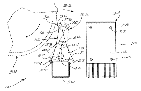
Figure 1 of the accompanying drawings illustrates a conveyor scraper element
10
according to a first form of the invention from a side and from one end
respectively.
In this example the conveyor scraper element includes a body 12 which is
moulded
from a suitable plastics material, eg. reinforced nylon, and which has a
roughly
triangular shape in cross section. An upper end or apex of the body has an
elongate
groove 14 which is narrower at its mouth than at its base. Sides 16 and 18 of
the
body taper outwardly and downwardly from the apex and are referred to herein
as
deflector surfaces.
At its lower end the body has two wings or ribs 20 and 22 respectively
projecting
downwardly from the deflecting sides 16 and 18.
A central portion of the body is formed with a fairly substantial slot 24
which has a
base 26 which is in the nature of a circular cylinder.
CA 02463468 2004-04-08
WO 03/053823 PCT/ZA02/00173
7
A scraping component 28 is mounted to the slot 14. The component 28 has a rib
30
which is of complementary shape to, and which is slideably engageable with,
the slot
14. The rib is held firmly in the slot by means of rivets or other fasteners
32 which
pass through holes in the upper end of the body 12 and registering holes in
the rib.
A scraping edge 34 of any appropriate scraping material known in the art is
mounted
to a slot 36 in a projecting outer surface of the component 28.
A leaf spring 40 is engaged with the formation 24. The spring has a rounded
upper
end 42 which is complementary in shape to the cylindrical base 26 of the
formation.
At its lower end the spring has a rounded base 44 which is positioned in a gap
formed at a central location in a mounting and supporting track 50.
The spring is made from a suitable material, eg. spring steel or an
appropriate
plastics material, with adequate corrosion resistant properties, which has an
acceptable cycle life time.
The support and mounting track or rail 50 is generally in the nature of an
inverted "U"
to fit over square tubing and has an upper elongate slotted formation 52 which
is
used for mounting the scraping component. The formation 52 corresponds in
shape
to the lower end of the spring 40 and the base 44. It is apparent that the
spring can
be engaged with a sliding action with the support by sliding the base 44 into
the
formation 52.
The geometry of the body and the design of the support 50 are such that, in
order for
the body to be engaged with the support, the spring must be prestressed. In
the
illustrated example this is achieved by bending the body in the direction of
an arrow
CA 02463468 2004-04-08
WO 03/053823 PCT/ZA02/00173
8
56 which is away from the surface 58 of a belt 60 which is to be cleaned. The
spring
is thereby flexed and the body can be pushed over the support with the ribs 20
and
22 extending downwardly on opposing sides of the support. Once the force which
is
used to bend the spring in the direction 56 is released, the spring attempts
to revert
to a neutral position and in so doing moves the body in a direction opposite
to that
indicated by the arrow 56, to a limited extent. A lower inner surface of the
rib 20 is
thereby brought into contact with an upper left hand corner of the support 50
and this
limits the degree to which the spring can relax. The spring is thereby held in
a
tensioned or prestressed state.
Figure 1 shows the scraper element 10 mounted adjacent the belt surface 58 and
acting as a primary scraper. The support 50 is positioned so that the scraping
edge
34 is lightly in contact with the belt surtace 58. The spring is, as noted,
constantly
held in a biased or prestressed condition.
The degree of flexing or pivoting of the body, which is permitted, is
restricted and the
body can move to a limiting position, away from the belt surface, indicated by
means
of a dotted line 62. At this stage the rib 22 abuts an upper right hand corner
of the
support 50 and this limits the permitted extent of movement of the body and
hence of
the scraping edge 34 away from the belt surface 58. The body is allowed
sufficient
movement to allow the scraper blade or edge 34 to follow variations in the
belt
thickness or undulations in its outer surface and to deflect sufficiently to
allow
protrusions, which are generally encountered, to pass the scraper edge. These
features have the following benefits:
(1 ) less applied pressure is required for the scraper element to resist the
forces of
CA 02463468 2004-04-08
WO 03/053823 PCT/ZA02/00173
9
the carry-back material on the belt, in order to perform its cleaning
function.
This reduces scraper blade and belt wear;
(2) deflection of the scraper element is limited thereby reducing rebound
impact;
(3) oscillation of the scraper element is restricted thereby interrupting any
vibration cycle and preventing sympathetic vibrations and resulting chatter,
damage etc.;
(4) in situations where the conveyor belt is reversed over the scraper
element,
forward movement of the scraper element is restricted, preventing it from
digging into the belt, an action which could damage the belt or the scraper
element;
(5) when the scraper element is used as a primary cleaning device the
restriction
on fonivard movement reduces the possibility of the scraper element being
snagged by a protrusion from the conveyor belt, a factor which could cause
damage to the belt or the scraper element.
Figure 2 illustrates a variation 10A of the arrangement shown in Figure 1
wherein the
scraper element is used as a secondary scraper. The configuration shown in
Figure
2 is not described in detail and, where applicable, components which are the
same
as those shown in Figure 1 are designated with similar reference numerals.
The upper edge of the body 12 has a scraping component 28A attached to it with
the
element being oriented so that the scraping edge 34A extends upwardly and not
to
the side, as in Figure 1. This allows the scraper element to be mounted in a
vertical
configuration, similar to what is shown in Figure 1, but with the scraping
edge being
available for a secondary scraping action as opposed to the primary scraping
action
of Figure 1.
CA 02463468 2004-04-08
WO 03/053823 PCT/ZA02/00173
Figure 2 also illustrates that the support, designated 50A, can be engaged
with a
sliding action with a base support 64. The base support 64 is attached to
fixed
structure adjacent a belt 60A, at an appropriate location, and the support
50A, which
is assembled with the scraping element or elements under factory conditions,
is then
5 readily engaged on-site by sliding the support 50A onto the base support 64.
Figure 3 shows a conveyor scraper element 10B which includes a body of two
metal
deflector plates 70 and 72 respectively which are joined at an apex formed by
upper
ends 74 to which a scraping component 76 is attached. The component 76 has a
scraping edge 78 of a suitable hard-wearing material fixed to it in a manner
which is
10 known in the art. The scraper element 10B is secured to the deflector
plates by
means of rivets or bolts 80.
The deflector plates extend downwardly and away from each other giving a
generally
triangular or pyramid-type construction. A leaf spring 82 of any suitable
material is
fixed to an inner surtace of the deflector plate 70. A lower end of the spring
is
clamped between angle brackets 84 which are fixed to an upper surface of a
support
50. A lower end of the deflector plate 70 abuts an upper left hand corner of
the
support 50 and retains the spring 82 in a permanently prestressed condition
with the
spring attempting to move to a neutral position in a direction of an arrow 86.
A lower end of the deflector plate 72, designated 88, is spaced from a right
hand
upper corner of the support 10. It is evident that the scraper element 10B is
similar to
what is shown in Figure 1 and that if the scraping edge 78 is moved in a
direction
opposite to that indicated by the arrow 86 the lower end 88 of the deflector
plate 72
CA 02463468 2004-04-08
WO 03/053823 PCT/ZA02/00173
11
limits the extent to which movement of the scraping edge can take place away
from a
belt surface which is being cleaned.
Apart from limiting the degree of movement of the spring 82 the deflector
plates
protect the spring and shield it, at least to some extent, from mechanical
damage,
and from foreign material, water and the like.
Figure 4 illustrates a scraper element 10C which is a variation of the
configuration
shown in Figure 3. The scraper element includes deflector plates 70A and 72A
respectively with the plate 70A being shaped in a different form to the plate
70. A
scraping component 76A, with a scraping edge 78A, is positioned between upper
edges of the plate 70A and 72A and is riveted in position.
A lower end of a centrally positioned spring 82A is clamped between two
brackets
84A which, in turn, are attached to a base plate 90. A channel 92 with
inwardly
sloping side walls is fixed to an upper surface of a support 50. The base
plate and
the brackets can be engaged with a sliding fit with the channel 92.
Although the scraper element 10C is a variation of the arrangement shown in
Figure
3 it is evident that it is used as a secondary scraper in a manner similar to
what has
been described in connection with Figure 2.
It is also to be noted, in connection with all of the embodiments of the
invention, that
only one scraper element has been described. It is evident that a plurality of
scraper
elements may be positioned in line with each other to form a longitudinally
extending
array of scraper elements with each scraper element being positioned above the
CA 02463468 2004-04-08
WO 03/053823 PCT/ZA02/00173
12
support 50. Clearly it is possible to arrange the scraper elements in other
configurations, eg. in a staggered array of two or more rows.
Another factor is that the support 50, in each embodiment of the invention,
may itself
be supported on a vertically and horizontally adjustable mounting 66, see
Figure 2, or
it may be supported on a torsion arm 68 which allows resilient movement, or it
may
be mounted to shock absorbing structures or self-support mechanisms such as
airbags, pneumatic or hydraulic cylinders, counteniveights or torsion-type
mounting
assemblies.
It is also possible to modify the conveyor scraper element to adjust the
degree of
bias, or prestressing, which is applied to the element. For example Figure 1
illustrates two grub screws 100 which are mounted in the body 12, bearing
against
the support 50, which can be adjusted to deflect the spring 40 to a greater or
lesser
extent, but which still act as a stop to prevent the spring from moving to a
de-stressed
condition.
Similarly, in Figure 3, a screw 102 which is fixed to the spring 82 bears
against an
inner surface of the deflector plate 70 and can be adjusted to increase or
reduce the
degree to which the spring is prestressed.