Note: Descriptions are shown in the official language in which they were submitted.
CA 02463575 2004-04-07
Description
PROTECTIVE RELAY CAPABLE OF PROTECTION APPLICATIONS
WITHOUT PROTECTION SETTINGS
Technical Field
This invention relates generally to protective relays
for electric power systems, and more particularly concerns a
current differential relay without conventional adjustable
settings which is useful in the protection of a power system.
Background of the Invention
Historically, digital protective relays have had an
adjustable "settings" capability, which enables a protection
engineer to customize the operation of a protective relay to a
particular protection' task in a power system. This is often a
challenging exercise. For example, with a conventional
overcurrent relay, the protection engineer must first determine
the expected fault current and the maximum load current of the
power system at the point in the system where the relay is
connected. The protection engineer then establishes the
operating settings of the overcurrent relay to provide a trip
signal when the currents it measures from the power line reach a
predetermined level above the maximum load current but below the
anticipated fault current.
The determination of the anticipated fault current
involves a rather complex calculation, which takes into account
the source strength and voltage, the impedance of downstream
transformers and the impedance of the line from the relay out to
the end of the protection zone covered by the relay. In
addition, the protection engineer must also often coordinate the
relay which is being set with other protective relays, located
both closer to the source and closer to the load than the relay
being set. Further, if the line protected by the relay being
set can provide power and serve load in both directions from the
protective relay, the setting task becomes even more
complicated.
CA 02463575 2010-07-05
2
The setting task also becomes more complicated when the
protection engineer must coordinate the protection provided by the
relay being set with other protective relays set by another entity,
an example being when utilities connect their respective power tie
lines together or when utilities connect to heavy industrial loads
having privately owned generators. Such connections are typically
referred to as "interties". The relays at both ends of the
intertie line portion must work together as a unit to properly
protect the intertie; hence, their respective settings must be
coordinated for proper operation and to prevent a malfunction,
which can occur in the event of miscalculation or misapplication of
a relay at either end of the intertie.
Accordingly, it is desirable for a protective relay to be
able to protect a variety of electric power arrangements and
configurations without the need to calculate and apply protective
relay settings. Further, it would be desirable to simplify the
protection of an intertie line portion to prevent misoperation of
the protection.
Summary of the Invention
Accordingly, in one aspect of the present invention,
there is provided a current differential protective relay without
user adjustable operational settings for use in protecting a
selected line portion of a power system, comprising: at least one
phase current differential element, having a first non-user
predetermined, fixed threshold value, responsive to phase currents
from the power system at a local location of the protective relay
and to phase currents from a remote relay on the selected line
portion, to detect three-phase faults on the selected line portion
and for providing a first output signal when said predetermined
threshold is exceeded by three-phase current; a first negative
sequence current differential element or two phase current
differential elements, having a second non-user predetermined,
fixed threshold value, responsive to said local phase currents and
said remote phase currents to detect phase-to-phase faults and
phase-to-phase-to-ground faults and for providing a second output
signal when said second predetermined threshold is exceeded,
CA 02463575 2010-07-05
3
wherein said two phase current differential elements include said
one phase current differential element for detecting three-phase
faults, or two additional phase current differential elements; and
a second negative sequence current differential element or a zero
sequence differential element, having a third non-user
predetermined, fixed threshold value, responsive to said local
phase currents and said remote phase currents to detect individual
phase-to-ground faults and providing a third output signal when
said third predetermined threshold is exceeded, wherein if one of
the negative sequence current differential elements is used, it is
either the first negative sequence current differential element
used for detecting phase-to-phase and phase-to-phase-to-ground
faults or the second negative sequence current differential
element, wherein the current differential elements include no
adjustable operational settings.
In a second aspect of the present invention, there is
provided a current differential protective relay without user
adjustable operational settings for use in protecting a selected
line portion of a power system: comprising: a first current
differential protection function, having a first non-user
predetermined, fixed threshold, but no adjustable operational
setting capability, responsive to phase currents from the power
system at a local location of the protective relay on the selected
line portion and to phase currents from a remote relay on the
selected line portion to detect three-phase faults on the line
portion and for providing a first output signal when said first
predetermined threshold is exceeded by three phase current; a
second current differential protection function, having a second
non-user predetermined, fixed threshold value, but no adjustable
operational netting capability, responsive to signals related to
said local phase currents and said remote phase currents to detect
phase-to-phase and phase-to-phase-to-ground faults and for
providing a second output signal when said second predetermined
threshold is exceeded; and a third current differential protection
function, having a third non-user predetermined, fixed threshold
value, but no adjustable operational netting capability, responsive
CA 02463575 2010-07-05
3a
to signals related to said local phase currents and said remote
phase currents to detect phase-to-ground faults and for providing a
third output signal when said third predetermined threshold is
exceeded.
In a third aspect of the present invention, there is
provided a current differential protective relay without adjustable
operational settings for use in protecting a selected line portion
of a power system, comprising: a first phase current differential
element, having a first predetermined, fixed threshold value,
responsive to phase currents from the power system at a local
location of the protective relay and to phase currents from a
remote relay on the selected line portion, to detect three-phase
faults on the line portion and for providing a first output signal
when said predetermined threshold is exceeded by three-phase
current; a second phase current differential element and a third
phase current differential element having a combined second
predetermined, fixed threshold value, collectively responsive to
said local phase currents and said remote phase currents to detect
phase-to-phase faults and phase-to-phase-to-ground faults and for
collectively providing a second output signal when said second
predetermined threshold is exceeded; and a negative sequence
current differential element or a zero sequence differential
element having a third predetermined, fixed threshold value,
responsive to said local phase currents, and said remote phase
currents to detect individual phase-to-ground faults and providing
a third output signal when said third predetermined threshold is
exceeded.
In a fourth aspect of the present invention, there is
provided a current differential protective relay without adjustable
operational settings for use in protecting a selected line portion
of a power system, comprising: at least one phase current
differential element, having a first predetermined, fixed
threshold, but no adjustable operational setting capability,
responsive to phase currents from the power system at a local
location of the protective relay on the selected line portion and
to phase currents from a remote relay on the selected line portion
CA 02463575 2010-07-05
3b
to detect three-phase faults on the line portion and for providing
a first output signal when said first predetermined threshold is
exceeded by three phase current; a first negative sequence current
differential element responsive to negative sequence current values
or at least one additional phase current differential element,
having a second predetermined, fixed threshold value but no
adjustable operational setting capability, responsive to signals
related to said local phase currents and said remote phase currents
to detect phase-to-phase and phase-to-phase-to-ground faults and
for providing a second output signal when said second predetermined
threshold is exceeded; and a second negative sequence current
differential element responsive to negative sequence current values
or a zero sequence current element responsive to zero sequence
current values, having a third predetermined, fixed threshold
value, but no adjustable operational setting capability, responsive
to signals related to said local phase currents and said remote
phase currents to detect phase-to-ground faults and for providing a
third output signal when said third predetermined threshold is
exceeded.
In a fifth aspect of the present invention, there is
provided a protective relay for current differential protection for
a selected power line, the protective relay comprising: a local
current differential relay for protection of a selected power line
portion of a power system, the local current differential relay
having the capability of sampling three phase current values from
its location on the power line at selected intervals of time and
transmitting them to a remote relay also connected to the selected
power line for current differential protection, wherein the remote
relay is not coordinated with the local current differential relay
for protection functions; and a sensing function in the local
current differential relay for determining when the relay is
connected to a remote relay which has adjustable settings for fault
determination, wherein the local current differential relay, upon
such determination, disables any protection functions therein while
continuing to provide phase current values to the remote relay and
to receive trip commands from the remote relay.
CA 02463575 2010-07-05
3c
Brief Description of the Drawings
Figure 1 is a diagram of a simple arrangement of a
current differential relay system.
Figure 2 is a block diagram showing the system of the
present invention.
CA 02463575 2004-04-07
4
Figure 3 is a simplified diagram showing a
conventional intertie arrangement.
Best Mode for Carrying Out the Invention
The present invention is a current differential relay
without the capability of, or the need for, conventional
adjustable settings. In current differential protection,
referring to Figure 1, a "local" relay 12 at one end of a
protected portion 13 of a power line obtains phase currents (A,
B and C phases) from the power line at that location and further
receives such currents obtained by a relay at a remote end of
the line, referred to as a remote relay 14. The sum of these
remote and local currents is then compared with a "pickup"
setting established for the particular application. Bi-
directional communication occurs over a link 16, with sampled
currents flowing in both directions. Circuit breakers 17 and 19
are responsive to the relays 12 and 14 to protect the line.
Conventional current differential protection can also be
accomplished by phase comparison of the current signals between
the relative phases of the remote and local currents, and
further, charge comparison, in which the area under the sine
wave of the current waveforms at the local and remote ends of
the protected line are compared to reach a trip decision.
The present invention is a current differential relay
having the capability of detecting all fault types without
adjustable settings. Several, individual conventional current
differential elements are combined to detect the various fault
types.
First, a conventional phase current differential
element is used to detect faults involving all three phases of a
power system, generally referred to as three-phase faults.
Phase current differential elements operate on the phase
currents (A, B, C) of the power signal. Three-phase faults flow
through relatively small impedances, such that the fault
currents will be relatively large. For example, a power system,
which is capable of delivering 5 amps of load current, will
typically deliver 20 amps or more of fault current due to a
three-phase fault. Typically, a single conventional phase
CA 02463575 2004-04-07
- a
current differential element is used for this, or alternatively,
three different elements'are used, one for each phase current.
A predetermined threshold is selected for the phase
current differential element so that it will reliably detect
5 three--phase faults for a large range of power system application.
possibilities. Such a threshold might. be 1 amp when the power
system is capable of delivering 5 amps of load current at the
input of the protective relay.
Second, the zero setting relay of the present
invention also protects phase-to-phase faults (A-B, B-C and
C-A), as well as phase-to-phase-to-ground faults. This is
accomplished by using either a conventional negative sequence
differential element, or two conventional phase current
differential elements. Negative sequence current is determined
conventionally via a well-known calculation/determination from
the three measured phase currents. The alternative two phase.
current differential elements can either include the phase
current differential element used to detect three-phase faults
and one additional phase current differential element, or they
can be two additional phase current differential elements.
Two-phase faults also, like three-phase faults,
create relatively large fault currents. It is thus possible to
select a predetermined threshold for the negative sequence
current differential element or the phase current differential
elements so that they will reliably detect phase-to-phase or
phase-to-phase-to-ground faults for a large range of possible
power system relay applications. For instance, a threshold of
1 amp could be selected, when the power system is capable of
delivering 5 amps of load current to the protective relay.
Third, the relay of the present invention uses a
negative sequence current differential element or a zero
sequence current differential element to detect phase faults
involving ground, i.e. single phase-to-ground faults (A-ground,
B-ground and C-ground). Since single phase-to-ground faults
often exhibit relatively high impedance, i.e. high resistance to
current flow, the fault currents generated are often small
compared to the load current that can be delivered by the power
CA 02463575 2004-04-07
6
system. Such faults are typically called high impedance or high
resistance faults. The negative sequence and zero sequence
differential currents determined by the current differential
relay when there is no power system fault are primarily due to
line charging current imbalance. Because the line charging
current is very small compared to the load currents which can be
delivered by the power system, the negative sequence or zero
sequence differential current elements can have a very low
operational threshold relative to the load current.
Zero sequence current differential elements are also
well known, operating on zero sequence current, which again is a
conventional determination obtained from measured phase
currents.
In one embodiment, a single negative sequence element
can be used to detect phase-to-ground faults and also phase-to-
phase and phase-to-phase-to-ground faults.
Because negative sequence and zero sequence current
differential elements can be established with very low
thresholds relative to the load current, it is possible to
select a threshold for those elements such that they will
reliably detect single phase-to-ground faults for a large range
of possible power system applications. Such a threshold in one
embodiment might be, for instance, O.S amps, if the power system
is capable of delivering 5 amps of load current at the input to
the protective relay.
Hence, in one embodiment of the zero setting relay of
the present invention one conventional phase current
differential element for detecting three-phase faults is
combined with a negative sequence differential current element
for detecting phase-to-phase, phase-to-phase-to-ground and
phase-to-ground faults for all three (A, B and C) phases. Both
the phase current differential element and the negative sequence
current differential element have prefixed thresholds.
The thresholds for the current differential elements
are set at the factory, and are hence not adjustable by the
protection engineer for a particular application. The
thresholds are designed to protect a wide range of possible
power system applications, within which the relay will operate
CA 02463575 2004-04-07
r
7
properly to detect faults. Hence, there is no opportunity for
an erroneous setting to cause a misoperation of the relay.
As alternative embodiments, two phase current
differential elements could be used for protection against
three-phase faults and phase-to-phase and .phase- to-phase-to
ground faults, or one phase current differential element could
be used for three-phase faults and two other phase current
differential elements (for a total of three) for phase-to-phase
and phase-to-phase to ground faults. In such embodiments, a
negative. sequence or zero sequence current differential element
could be used to detect phase-to-ground faults. In still
another alternative, a phase current differential element could
be used for three-phase faults, a negative sequence element
could be used for phase-to-phase faults, and another negative
sequence element or zero sequence element could be used for
phase-to-ground faults.
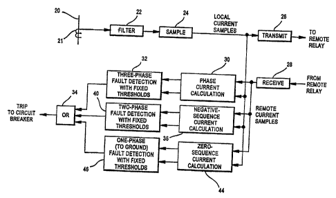
One particular combination is shown in Figure 2. The
three phase currents (A, B and C) are obtained from a power line
at the local relay through a power transformer 21 and then
20 filtered at block 22. The filtered currents are then sampled,
in a conventional manner, at block 24 and transmitted at block
26 to a remote relay. The local relay receives similar phase
current values from the remote relay at 28.
The local phase currents and the remote phase
currents are then each applied to three calculation circuits, as
shown. The first calculation circuit 30 results in a phase
current determination (where the local and remote phase current
values are added) with the results applied to a three-phase
fault detection circuit 32 with fixed thresholds, as discussed
above, such as by a phase current differential element or
elements. If the fixed threshold is exceeded, an output signal
from circuit 32 is applied to an OR gate 34.
A second calculation circuit 36 in Figure 2 is a
negative sequence current calculation circuit (although it could
be a phase current determination circuit as well, as discussed
above). The output of circuit 36 is applied to a phase-to-phase
and phase-to-phase-to-ground fault detection circuit 40, using a
negative sequence current element. If the fixed threshold of
CA 02463575 2004-04-07
8
the negative sequence element is exceeded, an output signal from
circuit 40 is applied to OR gate 34.
Third, the local and remote phase current values are
applied to a zero sequence calculation circuit 44 (in the zero
sequence current embodiment), the output of which is applied to
a single phase-to-ground fault detection circuit 46, using a
zero sequence current differential element with a fixed
threshold. If the threshold is exceeded by any of the phase-to-
ground currents, an output signal from circuit 46 is applied to
OR gate 34.
If there are one or more output signals applied to OR
gate 34, an output from OR gate 34 occurs, which is then applied
as a trip signal to the associated circuit breaker.
Hence, the present invention is a current
differential relay having a wide fault protection capability for
a wide range of protection applications, without the need for
settings by a protection engineer for a particular application.
Potential misoperations due to incorrect settings are thus
avoided.
As also discussed above, another challenge for the
protection engineer is the intertie situation in which the
protection engineer has access to only one end of the intertie
line portion. This is illustrated in Figure 3, in which an
intertie line portion 50 is protected by a zero setting current
differential relay 52 on one end of the protected line and a
traditional adjustable setting current differential relay 54 on
the other end of the line. Circuit breakers 56 and 58 are
located at the respective ends of the intertie line. The relays
52 and 54 are connected by a bidirectional communication link
64.
As stated above, the challenge for the protection
engineer is that when setting changes are made at one relay end
of the intertie, operation of the protection scheme may be
changed to some extent, resulting in a possible risk of
misoperation. Using a zero setting relay 52 at one end of the
intertie can help to resolve this particular issue, if that
relay in addition is designed to sense, i.e. determine, when it
is in fact connected to a conventional current differential
CA 02463575 2004-04-07
9
relay with adjustable settings, such as shown for the intertie
of Figure 3. In the present invention, when relay 52, with no
(zero) adjustable settings, does sense such a connection, it
will disable itself from performing current differential
protection and will only function to sample the local currents
and transmit them to the traditional current differential relay
with adjustable settings and to receive a trip command from the
other relay.
Relay 52 can make such a determination if the
traditional relay, i.e. relay 54, is designed to transmit a
particular, recognizable signal to the local relay 52. The
recognizable signal can take various forms, including for
example a particular bit in a data packet or a particular
pattern in a data packet. Even a particular format for the data
packet can be used, as well as other arrangements- Once the
zero setting relay 52 determines it is connected to such a
conventional relay, it is designed to go into its non-protection
mode. In operation, it will then only determine and transmit
local currents to the remote relay, in conventional fashion,
such as carried out by elements 21, 22, 24 and 26 of Figure 2.
The conventional adjustable settings relay 54 will use the
currents received from the non-protection-functioning zero
setting relay 52 along with its own locally measured currents to
perform traditional current differential protection, with its
own customized settings. If relay 54 determines that a fault
exists, it will first trip its local circuit breaker 58 and will
also send a trip command signal to the zero setting relay 52.
When relay 52 receives the signal, it will trip its own
associated circuit breaker 56.
Even though the zero setting relay 52 does not
provide any protection functions, it will trip at the same time
or shortly after the time when the traditional current
differential relay 54 trips its circuit breaker-due to relay 54
transmitting a trip command. The zero setting relay 52 thus in
effect operates in accordance with the settings of the remote
relay 54. Accordingly, there will be no misapplication or
misoperation of the overall current differential relay system
due to misapplied or miscalculated settings in relay 52.
CA 02463575 2004-04-07
Alternatively, it should be understood that relay 52,
while shown as a zero setting relay as discussed above, could
also be a conventional current differential relay with
adjustable settings, if it is programmed and designed so that
5 when it senses a connection with another. conventional adjustable
setting relay on an intertie application,- it disables its own
protection functions and operates only to obtain current samples
and transmit them to the remote relay, as well as receiving any
trip commands from the remote relay and thereafter tripping its
10 associated circuit breaker.
Still further, the relay 52 could be a completely
non-protection-function capable device, in effect a
teleprotection terminal capable only of obtaining local current
values, transmitting them to the remote intertie relay and
receiving back trip commands from the remote relay. Such a
terminal is still, however, referred to as a relay for the
purposes of this application.
Finally, although the application is disclosed in the
context of an intertie connection, it could be used in any
situation where there is no control over the settings of the
remote relay.
Accordingly, a system has been disclosed and claimed
which in one. case is capable of detecting a wide variety of
faults in a wide range of applications in a power system,
without the need for adjustable settings, i.e. a zero setting
relay.
In addition, the potential for mismatch in settings
for an intertie or similar line portion is overcome by an
arrangement involving either a zero setting relay, a
conventional relay, or a "relay" in the form of a teleprotection
terminal which, when a connection to a conventional, adjustable
setting relay is determined, disables its own protection
functions, if it has any, provides only sampled current values
to the remote relay, and receives only trip commands from the
remote relay.
Although a preferred embodiment of the invention has
been described for purposes of illustration, it should be
understood that various changes, modification and substitutions
CA 02463575 2004-04-07
11
might be incorporated in the embodiment without departing from
the spirit of the invention, which is defined in the claims,
which follow.