Note: Descriptions are shown in the official language in which they were submitted.
CA 02463984 2004-04-16
S P E C I F I C A T I 0 N
IGNITER
Field of the Invention
This invention relates to an igniter which ejects gas
and ignites the gas in response to operation of an actuator
which is supported for rotation about a fulcrum, and normally
prevents ignition by preventing rotation of the actuator or
by preventing full operation or reset of the igniting system
while permitting to ignite by releasing these preventions when
using the igniter.
Background of the Invention
An igniter, for instance, an igniting rod can ignite by
simply pushing an actuator. However, it is required to provide
the igniter with, for instance, a lock mechanism which prevents
the igniter from accidentally or unintentionally igniting, and
accordingly, there have been proposed various igniters
provided with various lock mechanisms.
For example, in Japanese Unexamined Patent Publication
No. 8(1996)-61673, there is disclosed an igniter in which a
lock member having a part which interferes with a part of an
actuator to prevent the igniter from igniting is provided to
be movable in a direction intersecting the direction of
movement of the actuator, an urging member is disposed to urge
the lock member toward its locking position, and the lock member
has a lock release portion for moving the lock member overcoming
1
CA 02463984 2004-04-16
the urging member in the vicinity of the actuator.
However such a lock mechanism is of a type in which the
actuator is slid and cannot be applied as it is to an igniter
of a type to which the present invention is applied and in which
the actuator is rotated
Further, in such a lock mechanism, it is necessary to
operate another member such as a lock release member remote
from the actuator prior to the igniting action by the actuator,
which makes it necessary a multiple stages of actions for the
igniting action, and deteriorates the operability of the
igniter. It is preferred that the lock mechanism be such that
the igniter can be stably shifted to an igniting state by a
series of actions and can be automatically shifted to the
initial state where ignition of the igniter is disabled in
response to release of the actuator from the finger.
In view of the foregoing observations and description,
the primary object of the present invention is to provide an
igniter having an actuator mechanism which can stably take the
ignition lock state so that the ignition lock state can be
easily released by a series of igniting actions.
Summary of the Invention
The igniter of the present invention comprises a gas
nozzle which is disposed in an end portion of a rod-like portion
and discharges gas, a reservoir storing therein fuel, a valve
mechanism for controlling supply of gas from the reservoir to
the gas nozzle, an ignition mechanism which generates a
2
CA 02463984 2004-04-16
discharge electric voltage for igniting the gas discharged from
the gas nozzle, and an actuator mechanism which is operated
to accomplish an igniting action of igniting the gas discharged
from the gas nozzle, wherein the improvement comprises that
the actuator mechanism comprises a rotatable actuator, a
fulcrum member which is supported on an igniter body casing
and about which the actuator is rotated and an interlocking
member which operates the ignition mechanism in response to
rotation of the actuator, and the igniting action of the
actuator involves rotation of the actuator about the fulcrum
member in one direction and an auxiliary operation of the
actuator to be done in continuous with rotation of the actuator,
in said one direction, in a direction different from said one
direction with the actuator mechanism automatically returned
to its initial state in response to return of the actuator to
its initial position.
It is preferred that the auxiliary operation of the
actuator be operation to move the fulcrum of the actuator. In
this case, it is preferred that the fulcrum member extends like
a stem on each side of the actuator to be fixed thereto and
be supported by a bearing portion, fixed to the igniter body
casing, to be able to support the actuator for rotation and
to be moved in the auxiliary operation in a direction
perpendicular to the direction of the axis of rotation of the
actuator.
An actuator mechanism in accordance with a first system
3
CA 02463984 2004-04-16
comprises a rotatable actuator, a fulcrum member which is
supported on an igniter body casing and about which the actuator
is rotated, an interlocking member which operates the ignition
mechanism in response to rotation of the actuator, a lock member
which engages to prevent rotation of the actuator, thereby
making an ignition lock, when the actuator is not operated,
and an urging member which urges the actuator toward its locking
position, wherein the igniting action of the actuator involves
making an auxiliary operation of the actuator in one direction
to release the engagement of the lock member and then rotating
the actuator in a direction different from the direction in
which the auxiliary operation of the actuator is made to release
the engagement of the lock member.
An example of the actuator mechanism in accordance with
the first system is provided with a pair of lock members which
are disposed between the fulcrum member and the igniter body
casing and are brought into engagement with each other under
the urging force of the urging member to make the ignition lock,
so that after release of ignition lock by an auxiliary operation
of the actuator in one direction to move the fulcrum member
overcoming the urging force of the urging member, the actuator
is rotated about the fulcrum member for the igniting action
in a direction different from the direction in which the
auxiliary operation of the actuator is made to release the
ignition lock. In this case, the lock members may be
projections which are formed on one of the fulcrum member and
4
CA 02463984 2004-04-16
the igniter body casing and are engaged with engagement
portions formed on the other of the fulcrum member and the
igniter body casing to make the ignition lock.
Another example of the actuator mechanism in accordance
with the first system is provided with a lock member which is
disposed between the interlocking member and the igniter body
casing and is brought into engagement under the urging force
of the urging member to make the ignition lock, so that after
release of ignition lock by an auxiliary operation of the
actuator in one direction to move the interlocking member
overcoming the urging force of the urging member, the actuator
is rotated for the igniting action in a direction different
from the direction in which the auxiliary operation of the
actuator is made to release the ignition lock. In this case,
the lock member may be a projection which is formed on one of
the interlocking member and the igniter body casing to
interfere with an engagement portion formed on the other of
the interlocking member and the igniter body casing to make
the ignition lock, and is passed through groves formed on the
interlocking member or the igniter body casing to permit
rotation of the interlocking member.
It is preferred that the urging member comprises a
pushing member which slides in response to movement of the
actuator toward the lock release direction and a spring which
urges the pushing member, and a part of the actuator be in
contact with the pushing member to be slidable in response to
5
CA 02463984 2004-04-16
rotation of the actuator.
An actuator mechanism in accordance with a second system
comprises a rotatable actuator, a fulcrum member which is
supported on an igniter body casing and about which the actuator
is rotated and an interlocking member which operates the
ignition mechanism in response to rotation of the actuator,
wherein rotation of the actuator is set so that the rotation
of the actuator by way of the interlocking member causes the
ignition mechanism to be operated by an amount not sufficient
to discharge electric voltage, the actuator is movable to a
position where it can operate the igniting member by way of
the interlocking member by an amount sufficient to discharge
electric voltage by an auxiliary operation of the actuator in
a direction different from the direction of the rotation of
the actuator, and the igniting action of the actuator involves
in addition to rotation of the actuator about the fulcrum member,
an auxiliary operation of the actuator in a direction different
from the direction of the rotation of the actuator to a position
where it can operate the igniting member by way of the
interlocking member by an amount sufficient to discharge
electric voltage.
Further, an actuator mechanism in accordance with a third
system comprises a rotatable actuator, a fulcrum member which
is supported on an igniter body casing and about which the
actuator is rotated, an interlocking member which operates the
ignition mechanism in response to rotation of the actuator and
6
CA 02463984 2004-04-16
a reset prevention member which prevents the ignition mechanism
from returning to a reset position, wherein the igniting action
of the actuator involves rotation of the actuator after the
ignition mechanism is returned to the reset position overcoming
the reset prevention member by an auxiliary operation of the
actuator in a direction different from the direction of the
rotation of the actuator. In this case, it is suitable for
the reset prevention member to prevent reset of the ignition
mechanism by urging the actuator toward the direction in which
the ignition mechanism is operated.
The auxiliary operation of the actuator in the actuator
mechanisms in accordance with the second and third systems is
suitably an operation to move the position of the fulcrum of
the actuator in parallel to the direction in which the ignition
mechanism is operated.
The interlocking member in each of the actuator
mechanisms in accordance with the first to third systems may
comprise a link member which transmits rotation of the actuator
to the ignition member.
In the interlocking member in each of the actuator
mechanisms in accordance with the first to third systems, at
least one of the valve mechanism and the ignition mechanism
cannot be operated and accordingly ignition of the igniter is
disabled unless the igniting action of the actuator involving
rotation of the actuator and the auxiliary operation is
continuously done, whereas when the actuator is rotated about
7
CA 02463984 2004-04-16
the fulcrum member and the auxiliary operation is done before
or after the rotation of the actuator continuously therewith,
the valve mechanism and the ignition mechanism can be operated
and the discharged gas can be ignited. When the actuator is
released, the actuator is automatically rotated back to
extinguish the igniter and the igniter automatically returns
to the initial state where the igniter cannot be ignited by
an incorrect operation of the actuator. When the igniter is
not in use, an inadvertent ignition of the igniter is thus
prevented.
For example, in an igniter provided with an actuator
mechanism in accordance with the first system, when the
actuator is not operated and in the lock position by the urging
member, the igniter is in the ignition lock state where the
lock member engages and rotation of the actuator is inhibited.
When the actuator is operated to release the ignition lock in
the auxiliary operation overcoming the urging member in a
direction different from the direction in which the actuator
is rotated, the lock member is disengaged to permit rotation
of the actuator, whereby fuel gas discharged in response to
igniting action of the actuator is ignited. When the actuator
is released, the actuator is automatically rotated back to the
initial position and the actuator is moved under the force of
the urging member to the lock state where the igniter cannot
be ignited by an incorrect operation of the actuator.
In an igniter provided with an actuator mechanism in
8
CA 02463984 2004-04-16
accordance with the second system, when the actuator is simply
rotated without the auxiliary operation, the ignition
mechanism cannot be operated by way of the interlocking member
by an amount sufficient to discharge electric voltage, and
accordingly, ignition of the igniter is disabled, whereas when
the auxiliary operation is carried out in a direction different
to the direction of rotation of the actuator in addition thereto,
the ignition mechanism is operated by way of the interlocking
member by an amount sufficient to discharge electric voltage
and an electric discharge takes place, whereby fuel gas
discharged is ignited. When the actuator is released, the
actuator is automatically returned to the position where it
requires the auxiliary operation to ignite the igniter.
In an igniter provided with an actuator mechanism in
accordance with the third system, since returning of the
ignition mechanism to the original state is prevented by the
reset prevention member and accordingly the ignition mechanism
cannot be reset, when the actuator is simply rotated without
the auxiliary operation, the ignition mechanism cannot be
operated, and accordingly, ignition of the igniter is disabled,
whereas when the actuator is rotated after the auxiliary
operation is carried out in a direction different to the
direction of rotation of the actuator to permit the ignition
mechanism to return to the reset position overcoming the reset
prevention member, an electric discharge takes place, whereby
fuel gas discharged is ignited. When the actuator is released,
9
CA 02463984 2004-04-16
the actuator is automatically returned to the position where
it requires the auxiliary operation to ignite the igniter.
In accordance with another aspect of the present
invention, there is provided an igniter which comprises a gas
nozzle which is disposed in an end portion of a rod-like portion
and discharges gas, a reservoir storing therein fuel, a valve
mechanism for controlling supply of gas from the reservoir to
the gas nozzle, an ignition mechanism which generates a
discharge electric voltage for igniting the gas discharged from
the gas nozzle, and an actuator mechanism which is operated
to accomplish an igniting action of igniting the gas discharged
from the gas nozzle, wherein the improvement comprises that
the actuator mechanism comprises an actuator which is movable
by a fulcrum member which is supported on an igniter body casing
and an interlocking member which operates the ignition
mechanism, and the ignition mechanism is brought into abutment
against the interlocking member to discharge an electric
voltage in response to movement of the actuator for ignition
and returns to the initial state in response to return of the
actuator to the initial position.
Further, in accordance with still another aspect of the
present invention, there is provided an igniter which comprises
a gas nozzle which is disposed in an end portion of a rod-like
portion and discharges gas, a reservoir storing therein fuel,
a valve mechanism for controlling supply of gas from the
reservoir to the gas nozzle, an ignition mechanism which
CA 02463984 2004-04-16
generates a discharge electric voltage for igniting the gas
discharged from the gas nozzle, and an actuator mechanism which
is operated to accomplish an igniting action of igniting the
gas discharged from the gas nozzle, wherein the improvement
comprises that the actuator mechanism comprises a rotatable
actuator, a fulcrum member which is supported on an igniter
body casing and about which the actuator is rotated, an
interlocking member which operates the ignition mechanism in
response to rotation of the actuator, a lock member which is
provided on the actuator and a part of which interferes with
the igniter body casing to inhibit rotation of the actuator
to make an ignition lock when the actuator is not operated,
and an urging member which urges the lock member toward the
lock position, the igniting action of the actuator involving
rotation of the actuator after releasing interference of the
lock member with the igniter body casing by lock release
operation with the actuator mechanism automatically returned
to its initial state in response to return of the actuator to
its initial position.
It is preferred that the lock release operation moves
the lock member along an actuating portion of the actuator
member. In this case, it is preferred that the lock member
comprises an actuating portion mounted on the actuator to be
slidable along the actuating portion of the actuator and a
locking portion which is formed contiguously to the actuator
and has an end portion which is able to be projected and
11
CA 02463984 2004-04-16
retracted from the actuator and can interfere with the igniter
body casing, and the urging member urges the locking portion
to project.
In such an igniter, when the lock member is not operated
and is held in the lock position under the force of the urging
member, the igniter is in the locked state where a part of the
lock member is in interference with the igniter body casing
and rotation of the actuator is inhibited. When the lock member
on the actuator is released from the igniter body casing
overcoming the urging member, rotation of the actuator is
permitted, whereby fuel gas discharged in response to igniting
action of the actuator is ignited. When the actuator is
released, the actuator is automatically rotated back to the
initial position and the lock member is moved under the force
of the urging member to the lock state where the igniter cannot
be ignited by an incorrect operation of the actuator.
In accordance with the igniters of the present invention,
since it is necessary to rotate the actuator and to accomplish
the auxiliary operation of the actuator in a direction
different from the direction in which the actuator is rotated
before or after the rotation of the actuator, or to release
ignition lock by the lock member on the actuator prior to
rotation of the actuator, it is difficult for those who do not
know correct use of the igniter to make the igniter in an
ignitable state or to release the ignition lock, whereby
inadvertent ignition of the igniter can be prevented, and at
Z2
CA 02463984 2004-04-16
the same time, since the igniter is automatically returned to
the initial state or the locked state where ignition of the
igniter is disabled, the igniter cannot be left in the ignitable
state. Further, in the extinguished state, the igniter can
be surely held in the un-ignitable state and the reliability
can be improved. Further, the auxiliary operation of the
actuator or the lock release operation of the lock member and
the igniting operation of the actuator can be smoothly done
in a series of actions which makes it unnecessary a multiple
stages of actions for the igniting action, and improves the
operability of the igniter, whereby stable ignition of the
igniter can be obtained.
Brief Description of Drawings
Figure 1 is a perspective view showing an appearance of
an igniter in accordance with a first embodiment of the present
invention,
Figure 2 is a cross-sectional view of the igniter taken
along a horizontal medial plane,
Figure 3 is a plan view partly in cross-section showing
the actuator mechanism of the igniter shown in Figure 2,
Figure 4 is a cross-sectional view taken along line I-I
in Figure 3,
Figure 5 is a cross-sectional view taken along line II-II
in Figure 3,
Figure 6 is a cross-sectional view taken along line
III-III in Figure 3,
13
CA 02463984 2004-04-16
Figure 7 is a cross-sectional view taken along line IV-IV
in Figure 3,
Figure 8 is a front view partly in cross-section showing
an important part shown in Figure 4 but in a lock release state,
Figure 9 is a side view partly in cross-section showing
an important part shown in Figure 5 but in a lock release state,
Figure 10 is a side view partly in cross-section showing
the important part shown in Figure 9 for illustrating ignition
from the state shown in Figure 9,
Figure 11 is a plan view partly in cross-section showing
the actuator mechanism of an igniter in accordance with a second
embodiment of the present invention,
Figure 12 is a cross-sectional view taken along line V-V
in Figure 11,
Figure 13 is a cross-sectional view taken along line
VI-VT in Figure 12,
Figure 14 is a front view partly in cross-section showing
an important part shown in Figure 12 but in a lock release state,
Figure 15 is a front view partly in cross-section showing
an important part shown in Figure 13 but in a lock release state,
Figure 16 is a side view partly in cross-section showing
the important part shown in Figure 14 for illustrating ignition
from the state shown in Figure 14,
Figure 17 is a side view partly in cross-section showing
the important part shown in Figure 16 but illustrating return
to the initial state from the state shown in Figure 16,
14
CA 02463984 2004-04-16
Figure 18 is a side view partly in cross-section showing
the actuator mechanism of an igniter in accordance with a third
embodiment of the present invention in its non-operated state,
Figure 19 is a side view partly in cross-section showing
the actuator mechanism of the igniter shown in Figure 18 for
illustrating rotation of the actuator,
Figure 20 is a side view partly in cross-section showing
the actuator mechanism of the igniter in a state where the
auxiliary operation has been further done from the state shown
in Figure 19,
Figure 21 is a side view partly in cross-section showing
the actuator mechanism of an igniter in accordance with a fourth
embodiment of the present invention in its non-operated state,
Figure 22 is a side view partly in cross-section showing
the actuator mechanism of the igniter shown in Figure 20 for
illustrating the auxiliary operation,
Figure 23 is a side view partly in cross-section showing
the actuator mechanism of the igniter in a state where rotation
of the actuator has been further done from the state shown in
Figure 22,
Figure 24 is a side view partly in cross-section showing
the actuator mechanism of an igniter in accordance with a fifth
embodiment of the present invention in its non-operated state,
Figure 25 is a side view partly in cross-section showing
the actuator mechanism of the igniter shown in Figure 24 for
illustrating rotation of the actuator,
CA 02463984 2004-04-16
Figure 26 is a side view partly in cross-section showing
the actuator mechanism of the igniter in a state where the
auxiliary operation has been further done from the state shown
in Figure 25,
Figure 27 is a side view partly in cross-section showing
the actuator mechanism of an igniter in accordance with a sixth
embodiment of the present invention in its non-operated state,
Figure 28 is a side view partly in cross-section showing
the actuator mechanism of the igniter shown in Figure 27 for
illustrating the auxiliary operation,
Figure 29 is a side view partly in cross-section showing
the actuator mechanism of the igniter in a state where rotation
of the actuator has been further done from the state shown in
Figure 28,
Figure 30 is a perspective view showing an appearance
of an igniter in accordance with a seventh embodiment of the
present invention,
Figure 31 is a cross-sectional view of the igniter taken
along a horizontal medial plane,
Figure 32 is a side view partly in cross-section showing
the actuator mechanism of the igniter shown in Figure 30,
Figure 33 is a cross-sectional view taken along line
VII-VII in Figure 32,
Figure 34 is a side view partly in cross-section showing
the support structure of the actuator mechanism shown in Figure
30,
16
CA 02463984 2004-04-16
Figure 35 is a side view partly in cross-section showing
an important part of the actuator mechanism shown in Figure
32 but in a lock release state, and
Figure 36 is a side view partly in cross-section showing
the important part of the actuator mechanism shown in Figure
32 in its igniting state.
Preferred Embodiments of the Invention
Embodiments of the present invention will be described
in detail with reference to the drawings, hereinbelow.
<First Embodiment>
The igniter of this embodiment is in the form of an
igniting rod and is shown in Figures 1 to 10. Figure 1 is a
perspective view showing an appearance of an igniter in
accordance with a first embodiment of the present invention,
Figure 2 is a cross-sectional view of the igniter taken along
a horizontal medial plane, Figure 3 is a plan view partly in
cross-section showing the actuator mechanism of the igniter,
Figures 4 to 7 are cross-sectional views of the parts shown
in Figure 3, and Figures 8 to 10 are cross-sectional views for
illustrating operation of the igniting rod. In these drawings
and the following drawings, hatching showing the
cross-sections of the reservoir portion, the valve mechanism
and the like is partly abbreviated.
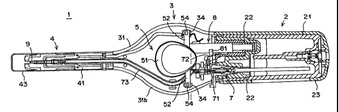
The igniter (igniting rod) 1 of this embodiment comprises,
as shown in Figures 1 and 2, a reservoir portion 2 which is
disposed in a base portion of the igniter 1 and stores therein
17
CA 02463984 2004-04-16
pressurized fuel gas such as butane gas, an actuator portion
3 which is disposed in an intermediate portion and in which
an actuator mechanism 5 for carrying out igniting operation
is disposed, and a rod-like portion 4 which extends forward
from the actuator portion 3 and is provided with a gas nozzle
9 in the end portion. The actuator mechanism 5 comprises an
actuator (actuator button) 51 which is rotated, and a valve
mechanism 7 which is interlocked with the actuator mechanism
5 to control supply of gas from the reservoir portion 2 to the
gas nozzle 9 in response to operation of the actuator mechanism
5, and a piezoelectric unit 8 which is an ignition mechanism
generating a discharge electric voltage for igniting the gas
discharged from the gas nozzle 9 and is interlocked with the
actuator mechanism 5 to generate the discharge electric voltage
in response to operation of the actuator mechanism 5 are
provided in the igniter 1.
The reservoir portion 2 comprises a reservoir body 21
which is tubular and has a bottom, a lid member 22 which closes
the open end of the reservoir body 21 and a reservoir cover
23 which is disposed to surround the reservoir body 21. The
valve mechanism 7 is a known one and is mounted on the lid member
22. The valve mechanism 7 has a nozzle member 71 which opened
and closed by an L-shaped lever 72 an end portion of which is
engaged with the nozzle member 71. Gas supplied by the valve
mechanism 7 is supplied to the gas nozzle 9 in the end portion
of the rod-like portion 4 by way of a gas pipe 73.
18
CA 02463984 2004-04-16
The actuator portion 3 is provided with an igniter body
casing 31 (igniter body) which is horizontally divided into
upper and lower halves 31a and 31b, and an inner tube 41 of
the rod-like portion 4 is integrally formed with the front end
portion of the igniter body casing 31. The rod-like portion
4 has the gas nozzle 9 connected to the front end of the gas
pipe 73 at a central portion of the front end portion of the
inner tube 41, and a rod-like metal tubular body 43 is fitted
on the outside of the inner tube 41 so that flame is ejected
from a flame port which opens in the front end face of the metal
tubular body 43. An electrode (not shown) is provided in the
metal tubular body 43 to project near to the gas nozzle 9.
A window portion 32 opens in the upper half 31a of the
igniter body casing 31 and the actuator 51 of the actuator
mechanism 5 is disposed at the center of the window portion
32. A protective portion 33 projects from the upper half 31a
of the igniter body casing 31 along the peripheral edge of the
window portion 32. The protective portion 33 is formed to
surround the actuator 51 with its front portion higher.
The actuator mechanism 5 comprises the actuator 51 which
is rotatable and is provided with an actuating portion 51a on
its surface, a shaft-like fulcrum member 52 about which the
actuator 51 is rotated in a direction perpendicular to the
centerline of the valve mechanism 7, an interlocking member
53 (an interlocking lever) which operates the piezoelectric
unit 8 in response to rotation of the actuator 51, a lock member
19
CA 02463984 2004-04-16
54 which makes an ignition lock, by inhibiting rotation of the
actuator 51 and an urging member 6 which urges the actuator
51 toward its locking position.
The piezoelectric unit 8 is disposed between the actuator
51 and the lid member 22 to generate a discharge voltage in
response to rotation of the actuator 51, and is provided with
a projection 81 on the sliding portion thereof . The projection
81 is brought into abutment against the end portion of the
L-shaped lever 72 when the sliding portion is moved rearward
upon igniting operation of the actuator mechanism 5 to rotate
the L-shaped lever 72, whereby the nozzle member 71 of the valve
mechanism 7 is opened and gas is supplied. The discharge
voltage generated by the piezoelectric unit 8 is led to the
gas nozzle 9 and the electrode in the rod-like portion 4 by
way of a known energizing mechanism and an ignition spark is
generated therebetween.
The actuator 51 of the actuator mechanism 5 is
ellipsoidal in plan and higher in the front portion facing the
rod-like portion 4 than the rear portion. That is, the upper
surface of the actuator 51 forming the actuating portion 51a
is inclined to be higher forward, and when the igniter 1 is
to be ignited, i . e. , for igniting operation, a user' s finger
is applied to the actuating portion 51a and the actuating
portion 51a is pushed forward. The igniting operation of the
actuator 51 involves rotation of the actuator 51 about the
fulcrum member 52 and an auxiliary operation of the same in
CA 02463984 2004-04-16
a direction different from the direction of rotation to be done
in continuous with rotation of the actuator. In this
particular embodiment, the auxiliary operation of the actuator
51 is downward depression of the rear portion of the actuator
51.
As shown in Figures 3 to 5, the base end of the fulcrum
member (rotary shaft) 52 which is like a laterally extending
round rod is fixed to the lower portion of the actuator member
51 near to the reservoir portion 2 on opposite sides of the
actuator 51 and a pair of bearing portions 34 are erected on
the bottom of the lower half 31b of the igniter body casing
31 on opposite sides of the bottom of the lower half 31b. A
bearing groove 34a (Figure 5) is formed in the top end of each
of the bearing portions 34 to be vertically long. The fulcrum
member 52 is received in the bearing grooves 34a of the bearing
portions 34, whereby the actuator 51 is supported on the fulcrum
member 52 so that the front end portion thereof is rotatable
and the rear end portion thereof is movable up and down.
In this particular embodiment, lock members 54 which
inhibit rotation of the actuator 51 to disable ignition of the
igniter 1 by preventing revolution of the fulcrum member 52
are provided. That is, the fulcrum member S2 is provided with
a lock member 54 (engagement projection) in the form of a
projection on the upper portion of each of opposite end portions
thereof. The lock members 54 are adapted to be engaged with
a groove-like engagement portions 35a formed on the lower
21
CA 02463984 2004-04-16
surface of the upper half 31a of the igniter body casing 31.
When the lock members 54 are engaged with the groove-like
engagement portions 35, revolution of the fulcrum member 52,
that is, rotation of the actuator 51, is inhibited, whereby
the igniter 1 is brought into the locked state. The auxiliary
operation to release the lock of the igniter 1 is carried out
by depressing the rear end portion of the actuator 51 to move
downward the fulcrum member 52 so that the lock members 54 are
disengaged from the engagement portions 35 and rotation of the
20 actuator 51 is permitted. Though, in the illustrated
embodiment, the lock member 54 is a rectangular projection and
the engagement portion 35 is in the form of a recessed groove,
the lock member 54 may be like a pin with the engagement portion
35 like hole. Further, inversely to the case described above,
a projecting lock member may be formed on the lower surface
of the upper half 31a of the igniter body casing and a recessed
engagement portion may be formed on the fulcrum member 52.
As shown in Figure 6, the actuator 51 is provided with
a downward extending projection 51b on its lower surface near
the center of the fulcrum member 52 and the projection 51b is
urged upward by the urging member 6. The urging member 6 is
provided with a pressing member 62 which is slidable up and
down in a guide portion 61 formed on the bottom of the lower
half 31b of the igniter body casing 31, and a coiled spring
63 is compressed by the pressing member 62, whereby the pressing
member 62 is urged upward by the coiled spring 63. The top
22
CA 02463984 2004-04-16
surface of the pressing member 62 is formed in a concave arcuate
surface and the lower end of the projection 51b formed in a
convex arcuate surface is in abutment against the top surface
of the pressing member 62, whereby the lower end of the
projection 51b and the top surface of the pressing member 62
are in contact with each other to be slidable relatively to
each other even if the actuator 51 has been rotated and the
rear end portion of the actuator 51 and the fulcrum member 52
are urged upward to the lock position.
Further, as shown in Figure 7, the actuator 51 is provided
with an interlocking member 53 extending downward from a rear
end portion of the actuator 51. The front end of the
piezoelectric unit 8 abuts against the lower rear end of the
interlocking member 53 so that the piezoelectric unit 8 is moved
rearward by the interlocking member 53 in response to rotation
of the actuator 51. The return spring (not shown) built in
the piezoelectric unit 8 urges the interlocking member 53
toward its initial position, whereby the front end portion of
the actuator 51 is urged to rotate upward.
As shown in Figure 4, a reinforcing rib 55 extending from
the actuator 51 to the lower end of the fulcrum member 52 on
opposite sides of the actuator 51 reinforces the fulcrum member
52.
Operation of the igniter 1 of this embodiment will be
described, hereinbelow. That is, when the igniter 1 is in its
non-operated state (left to stand still) where the actuator
23
CA 02463984 2004-04-16
51 is not operated as shown in Figures 1 to 7, the actuator
51 and the fulcrum member 52 are held in their lifted positions
under the force of the urging member 6, and the lock members
54 are in engagement with the engagement portions 35. In this
state, the actuator 51 cannot be rotated since rotation of the
fulcrum member 52 is inhibited. That is, the igniter 1 is
locked.
When the igniter 1 is to be ignited, auxiliary operation
is done. That is, a finger is applied to the actuating portion
51a of the actuator 51, and the rear end portion of the actuator
51 is depressed in the direction of the arrow overcoming the
force of the urging member 6 as shown in Figures 8 and 9. By
the auxiliary operation, the fulcrum member 52 is moved
downward and the lock members 54 are disengaged from the
engagement portions 35, whereby the igniter 1 is turned to the
lock release state, where rotation of the actuator 51 is
permitted.
When the front end portion of the actuator 51 is depressed
in the direction of the arrow in Figure 10 to rotate the actuator
51 with the rear end portion of the actuator 51 held in the
depressed state by the auxiliary operation, the interlocking
member 53 moves rearward the piezoelectric unit 8 so that the
projection 81 rotates the lever 72, whereby the nozzle member
71 is lifted to open the valve mechanism 7 and gas is supplied
to the gas nozzle 9 through the gas pipe 73. Further, a
discharge voltage is generated in response to operation of the
24
CA 02463984 2004-04-16
piezoelectric unit 8 and an electric spark is generated between
the electrode in the rod-like portion 4 and the gas nozzle 9,
whereby the discharged gas is ignited.
When depression of the actuator 51 is released or the
finger which has been applied to the actuating portion 51a is
released for interrupting use of the igniter 1, the actuator
51 is rotated in the reverse direction to return to the initial
position by way of the interlocking member 53 under the force
of the return spring (not shown) in the piezoelectric unit 8
and at the same time, the fulcrum member 52 is rotated in the
reverse direction to the position where the lock members 54
and the engagement portions 35 can be engaged with each other
and the fulcrum member 52 is lifted under the force of the urging
member 6 so that the lock members 54 and the engagement portions
35 are engaged with each other, whereby the igniter I, is
automatically returned to the locked state.
Though, in the above embodiment, the fulcrum member 52
is fixed to the actuator 51, the fulcrum member 52 may be mounted
on the igniter body casing 31 to support the actuator 51 for
rotation and up-and-down movement. In this case, the fulcrum
member 52 is fixed to be neither rotated nor moved up and down
while supporting the actuator 51 to be movable up and down by
way of, for instance, an elongated hole, and the lock member
54 is disposed between the fulcrum member 52 and the actuator
51 so that the lock member 54 is disengaged in response to an
auxiliary operation of depressing the actuator 51 to move
CA 02463984 2004-04-16
downward the same.
Further, the urging member 6 may be arranged to urge the
fulcrum member 52 . For example, an urging member 6 which urges
upward the end portion of the fulcrum member 52 may be provided
on the bearing portion 34.
Further, the igniting mechanism for generating a
discharge voltage may comprise a discharge circuit using a cell
in place of the piezoelectric unit 8. This is the same in all
the embodiments to be described later.
In accordance with this embodiment, it is necessary to
perform, prior to rotation of the actuator 51, an auxiliary
operation of lock release by depressing the rear end portion
of the actuator 51 in a direction different from the direction
in which the actuator 51 is rotated. In an unused state, the
lock members 54 and the engagement portions 35 are constantly
engaged with each other to disable the igniter 1 from being
ignited, and after use of the igniter 1, the igniter 1 is
automatically returned to the Locked state. Accordingly,
inadvertent ignition of the igniter can be prevented, and at
the same time, the auxiliary operation of lock release and
rotation of the actuator for ignition can be smoothly carried
out, whereby good operability can be obtained.
<Second Embodiment>
An igniter in accordance with another embodiment of the
present invention is shown in Figures 11 to 17. Figure 11 is
a plan view partly in cross-section showing the actuator
26
CA 02463984 2004-04-16
mechanism of the igniter, Figures 12 to 14 are cross-sectional
views of the parts shown in Figure 11, and Figures 15 to 17
are cross-sectional views for illustrating operation of the
igniting rod.
The igniter (igniting rod) 10 of this embodiment is the
same as the first embodiment except the actuator mechanism 50,
and accordingly, the analogous elements are given the same
reference numerals.
The actuator mechanism 50 of the igniter of this
embodiment comprises an actuator 51 similar to that of the first
embodiment, and the actuator 51 is held by a fulcrum member
52 on its opposite sides to be rotatable and movable up and
down. The actuator 51 has on its rear end portion an
interlocking member 53 which extends downward and actuates the
piezoelectric unit 8. Further the rear end portion of the
actuator 51 is urged upward or toward its lock position by an
urging member 6 which is of the same structure as that of the
first embodiment. The igniting operation of the actuator 51
involves rotation of the actuator 51 about the fulcrum member
52 and an auxiliary operation of the same in a direction
different from the direction of rotation to be done in
continuous with rotation of the actuator. In this particular
embodiment, the auxiliary operation of the actuator 51 is
downward depression of the rear portion of the actuator 51.
Lock members 57 for carrying out the ignition lock by
inhibiting rotation of the actuator 5I are provided to inhibit
27
CA 02463984 2004-04-16
movement of the interlocking member 53. That is, a bracket
37 is erected on the bottom of the lower half 31b of the igniter
body casing 31 on a side of the interlocking member 53, and
the bracket 37 has one of the lock members 57 (engagement
projection) on its side surface facing the interlocking member
53. Further, the urging member 6 has another of the lock
members 57 on the side surface of a frame-like guide portion
61 thereof facing the interlocking member 53.
Each of the lock members 57 is a pin-like projection which
is adapted to be engaged with the rear end of an engagement
portion 53a formed on the end of the interlocking member 53.
When the lock member 57 is engaged with the engagement portion
53a, rotation of the interlocking member 53, that is, rotation
of the actuator 51, is inhibited and the igniter is brought
into the locked state. The auxiliary operation to release the
lock is to depress the rear end portion of the actuator 51 to
move downward the interlocking member 53 so that the lock member
57 is disengaged from the engagement member 53a and moved into
a groove 53b formed in the side of the interlocking member 53,
thereby permitting rotation of the actuator 51.
The groove 53b is formed arcuately about the fulcrum
member 52 to extend from the front end portion to the rear end
portion of the interlocking member 53. Further, the
engagement portion 53a on the lower end of the groove 53b is
cut away on the side facing the rear end of the groove 53b and
the upper portion of the lock member 57 faces the rear end of
28
CA 02463984 2004-04-16
the groove 53b in the engaged state shown in Figure 12 . Further,
the front end portions of the grooves 53b are tapered in the
vertical direction to guide the lock members 57 upon returning
to the initial position.
Though, in the illustrated embodiment, the pin-like lock
members 57 are provided on the bracket 37 and the guide portion
61, and the engagement portions 53a and the grooves 53 are
provided on the interlocking member 53, the engagement portions
53a and the grooves 53 may be provided on the bracket 37 and
the guide portion 61, and the pin-like lock members 57 may be
provided on the interlocking member 53, inversely to the
illustrated embodiment. Further, though, in the illustrated
embodiment, the lock member 57 is provided on each side of the
interlocking member 53, the lock member 57 may be provided on
one side of the interlocking member 53.
In this embodiment, when the igniter 1 is in its
non-operated state (left to stand still) where the actuator
51 is not operated as shown in Figures 12 and 13, the actuator
51 and the interlocking member 53 are held in their lifted
positions under the force of the urging member 6, and the lock
members 57 axe in engagement with the engagement portions 53a.
In this state, the actuator 51 cannot be rotated since rotation
of the interlocking member 53 is inhibited. That is, the
igniter 1 is locked.
When the igniter 1 is to be ignited, auxiliary operation
is done. That is, a finger is applied to the actuating portion
29
CA 02463984 2004-04-16
51a of the actuator 51, and the rear end portion of the actuator
51 is depressed in the direction of the arrow overcoming the
force of the urging member 6 as shown in Figures 14 and 15.
By the auxiliary operation, the interlocking member 53 is moved
downward and the lock members 57 are disengaged from the
engagement portions 53a into the grooves 53b, whereby the
igniter 1 is turned to the lock release state, where rotation
of the actuator 51 is permitted.
When the front end portion of the actuator 51 is depressed
in the direction of the arrow in Figure 16 to rotate the actuator
51 with the rear end portion of the actuator 51 held in the
depressed state by the auxiliary operation, the interlocking
member 53 rotates with the lock members 57 moved through the
grooves 53b to move rearward the piezoelectric unit 8, whereby
the nozzle member 71 is lifted to open the valve mechanism 7
and gas is supplied to the gas nozzle 9 through the gas pipe
73. Further, the discharged gas is ignited by the electric
voltage discharge.
When depression of the actuator 51 is released to
interrupt use of the igniter 1, the interlocking member 53 and
the actuator 51 are rotated in the reverse direction to return
to the initial position under the force of the return spring
in the piezoelectric unit 8. At this time, the lock member
57 is passed through the groove 53b of the interlocking member
53 from the front end portion to the rear end portion and returns
to the initial position. Thereafter the interlocking member
CA 02463984 2004-04-16
53 is lifted under the force of the urging member 6 so that
the lock members 57 and the engagement portions 53a are engaged
with each other, whereby the igniter 1 is automatically
returned to the locked state. When the actuator 51 is released
from the finger and the interlocking member 53 is lifted upward
under the force of the urging member 6 before the actuator 51
is rotated back to the initial position, the lock member 57
is returned to the initial position under the guidance of the
front side curved surface of the groove 53b.
Also, in accordance with this embodiment, desired lock
function and lock release function are obtained and at the same
time, an automatic return of the igniter to the locked state
can be obtained. Further, the operability of the igniter is
excellent.
The auxiliary operation of the actuator (the lock release
operation) need not be limited to those in the preceding
embodiments but may be performed in any direction so long as
it is different from the direction of rotation of the actuator.
For example, the auxiliary operation of the actuator may be
performed back and forth or left and right other than up and
down . The lock member may be arranged to engage and disengage
according to the direction of the auxiliary operation.
<Third Embodiment>
Figures 18 to 20 show an igniter in accordance with
another embodiment of the present invention. Figure 18 is a
side view partly in cross-section showing the actuator
31
CA 02463984 2004-04-16
mechanism in its non-operated state, Figure 19 is a side view
partly in cross-section showing the actuator mechanism shown
in Figure 18 for illustrating rotation of the actuator, and
Figure 20 is a side view partly in cross-section showing the
actuator mechanism in a state where the auxiliary operation
has been further done from the state shown in Figure 19.
The igniter (igniting rod) 100 of this embodiment is the
same as the first embodiment except the actuator mechanism 150,
and accordingly, the analogous elements are given the same
reference numerals.
The actuator mechanism 150 of the igniter of this
embodiment comprises an actuator 151 similar to that of the
first embodiment in appearance and provided with an actuating
portion 151a on its surface, and the actuator 151 is held by
a fulcrum member 152 on its opposite sides for rotation and
back-and-forth movement on the top ends of bearing portions
139. The actuator 151 has on its rear end portion an
interlocking member 153 which extends downward and actuates
the piezoelectric unit 8 . That is, the base end of the fulcrum
member (rotary shaft) 152 which is like a laterally extending
round rod is fixed to the lower portion of the actuator member
151 near to the reservoir portion 2 on opposite sides of the
actuator 51 and a pair of bearing portions 134 are erected on
the bottom of the lower half 31b of the igniter body casing
31 on opposite sides of the bottom of the lower half 31b. A
bearing groove 134a is formed in the top end of each of the
32
CA 02463984 2004-04-16
bearing portions 134 to be vertically long. The fulcrum member
152 is received in the bearing grooves 134a of the bearing
portions 134, whereby the actuator 151 is supported on the
fulcrum member 152 so that the front end portion thereof is
rotatable and the whole actuator 151 is movable back and. forth
in parallel to the direction of operation of the piezoelectric
unit 8.
The igniting operation of the actuator 151 involves
rotation of the actuator 151 about the fulcrum member 152 and
an auxiliary operation of the same in a direction different
from the direction of rotation to be done in continuous with
rotation of the actuator 151. In this particular embodiment,
the auxiliary operation of the actuator 51 is rearward movement
of the whole actuator 151 in parallel to the direction of
operation of the piezoelectric unit 8. The piezoelectric unit
8 discharges a discharge voltage when its front end is moved
rearward to a discharge position P.
The actuator 151 is arranged so that the fulcrum member
152 is positioned in the forward position in the bearing groove
134a of the bearing portion 134 as shown in Figure 18 in the
non-operated state or the returned state and a maximum rotation
of the actuator 151 in this state causes the interlocking member
153 to operate the piezoelectric unit 8 by an amount smaller
than the amount of operation to the discharge position P by
an amount d as shown in Figure 19. That is, the piezoelectric
unit 8 can discharge no electric voltage in this state.
33
CA 02463984 2004-04-16
The amount of movement of the auxiliary operation to move
the fulcrum member 152 to the rearward position in the bearing
groove 134a of the bearing portion 134 is larger than the amount
d so that, in addition to rotation of the actuator 151,
auxiliary operation of the actuator 151 in the rearward
direction shown by the arrow different from the direction of
rotation of the actuator 151 can cause the interlocking member
153 to operate the piezoelectric unit 8 to the discharge
position P as shown in Figure 20. That is, the piezoelectric
unit 8 can generate a discharge voltage.
In this embodiment, unless the auxiliary operation of
the actuator 151, the fulcrum member 152 is positioned in the
forward position in the bearing groove 134a of the bearing
portion 134 as shown in Figure 18 and a rotation of the actuator
151 in this state causes the interlocking member 153 to operate
the piezoelectric unit 8 by an amount smaller than the amount
of operation to the discharge position P by an amount d as shown
in Figure 19. That is, the igniter is disabled from ignition.
When the auxiliary operation to move rearward the actuator 151
as shown by the arrow in Figure 20 is carried out in addition
to rotation of the actuator 151, the interlocking member 153
comes to be able to operate the piezoelectric unit 8 to the
discharge position P as shown in Figure 20. That is, the
piezoelectric unit 8 can generate a discharge voltage to ignite
gas discharged from the gas nozzle. The auxiliary operation
may be carried out prior to rotation of the actuator 151.
34
CA 02463984 2004-04-16
When rotation and auxiliary operation of the actuator
151 is released to interrupt use of the igniter, the
interlocking member 153 and the actuator 151 are rotated in
the reverse direction and are moved forth to return to the
initial position shown in Figure 18 under the force of the
return spring in the piezoelectric unit 8 . That is, the igniter
is automatically returned to a state where ignition of the
igniter is disabled.
Also, in accordance with this embodiment, ignition lock
to prevent the igniter from being ignited by simple rotation
of the actuator 151 can be ensured and the ignition lock can
be released in a series of actions and at the same time, an
automatic return of the igniter to the locked state can be
obtained. Further, the operability of the igniter is
excellent.
<Fourth Embodiment>
Figures 21 to 23 show an igniter in accordance with
another embodiment of the present invention. Figure 21 is a
side view partly in cross-section showing the actuator
mechanism in its non-operated state, Figure 22 is a side view
partly in cross-section showing the actuator mechanism shown
in Figure 21 after the auxiliary operation has been done, and
Figure 23 is a side view partly in cross-section showing the
actuator mechanism in a state where the actuator has been
rotated from the state shown in Figure 22.
The igniter (igniting rod) 200 of this embodiment is the
CA 02463984 2004-04-16
same as the preceding embodiment except the actuator mechanism
250, and accordingly, the analogous elements are given the same
reference numerals.
The actuator mechanism 250 of the igniter of this
embodiment comprises an actuator 151 similar to that of the
third embodiment, and the actuator 151 is held by a fulcrum
member 152 on its opposite sides for rotation and
back-and-forth movement along bearing grooves 134a formed in
the top ends of the bearing portions 134 to be long back and
forth in parallel to the direction of operation of the
piezoelectric unit 8. The actuator 153 has an interlocking
member 153 which extends downward to operate the piezoelectric
unit 8 on its rearward portion.
In this particular embodiment, the igniting operation
of the actuator 151 involves rotation of the actuator 151 about
the fulcrum member 152 and an auxiliary operation of the same
in a direction different from the direction of rotation to be
done in continuous with rotation of the actuator 151. In this
particular embodiment, the auxiliary operation of the actuator
151 is forward movement of the whole actuator 151 in the
direction reverse to the direction of operation of the
piezoelectric unit 8. The piezoelectric unit 8 discharges an
electric voltage when the front end is moved rearward to the
discharge position P and when the front end is returned to the
reset position S, the piezoelectric unit 8 comes to be able
to discharge again.
36
CA 02463984 2004-04-16
The actuator mechanism 250 is provided with a reset
prevention member 260 which prevents the piezoelectric unit
8 from being moved forward up to the reset position S. The
reset prevention member 260 comprises a pressing member 262
which slides back and forth in a guide portion 161 provided
on a protective portion 33 of the upper half 31a of the igniter
body casing 3I forward of the actuator 151, and the pressing
member 262 is urged rearward by a coiled spring 263 (may be
resilient material such as a leaf spring, a resin spring or
the like) . The rear end of the pressing member 262 constantly
abuts against the front end of the actuator 151 even if the
actuator 151 is rotated to urge rearward the actuator 151 so
that the piezoelectric unit 8 cannot be fully returned to the
initial position.
In the non-operated state or the returned state from the
preceding igniting action shown in Figure 21, the reset
prevention member 260 urges rearward the piezoelectric unit
8 by way of the actuator 151 and the interlocking member 153
so that the piezoelectric unit 8 stops short of the reset
position S . That is, the reset prevention member 260 prevents
movement of the fulcrum member 152 to the rearward position
in the bearing groove 134a until the auxiliary operation of
the actuator 151 is done. In the non-operated state, the
piezoelectric unit 8 cannot be reset and rotation of the
actuator 151 from this position cannot cause the piezoelectric
unit 8 to discharge an electric voltage even if the
37
CA 02463984 2004-04-16
piezoelectric unit 8 is operated to the discharge position P.
The amount of movement of the auxiliary operation to move
the fulcrum member 152 to the forward position in the bearing
groove 134a of the bearing portion 134 is to permit the
piezoelectric unit 8 to return to the reset position S so that
auxiliary operation of the actuator 151 in the forward
direction shown by the arrow in Figure 22 different from the
direction of rotation of the actuator 151 prior to rotation
of the actuator 151 permits the interlocking member 153 to
operate the piezoelectric unit 8 to the reset position S as
shown in Figure 22. That is, the piezoelectric unit 8 can
generate a discharge voltage by subsequently operating it to
the discharge position P.
In the initial state where the auxiliary operation of
the actuator 151 has not been carried out, the fulcrum member
152 for the actuator member 151 is in the rearward position
in the bearing groove 134a of the bearing portion 134 and the
piezoelectric unit 8 has not been reset. Rotation of the
actuator 151 in this state cannot cause the piezoelectric unit
8 to discharge an electric voltage . That is, ignition of the
igniter is disabled. When auxiliary operation to move forward
the actuator 151 in the direction of the arrow in Figure 22
overcoming the force of the reset prevention member 260 is
carried out, the piezoelectric unit 8 can be reset and rotation
of the actuator 151 causes the piezoelectric unit 8 to discharge
an electric voltage in response to rearward movement of the
38
CA 02463984 2004-04-16
piezoelectric unit 8 to the discharge position P, whereby gas
discharged from the gas nozzle is ignited. Rotation of the
actuator 151 may be carried out in the rearward position after
the auxiliary operation.
When rotation and auxiliary operation of the actuator
151 is released to interrupt use of the igniter, the
interlocking member 153 and the actuator 151 are rotated in
the reverse direction and are moved forth to return to the
initial position shown in Figure 21, where return of the
piezoelectric unit 8 to the reset position S is prevented by
the reset prevention member 260, under the force of the return
spring in the piezoelectric unit 8. That is, the igniter is
automatically returned to a state where ignition of the igniter
by a simple rotation of the actuator 151 is disabled.
Also, in accordance with this embodiment, ignition lock
to prevent the igniter from being ignited by simple rotation
of the actuator 151 can be ensured and the ignition lock can
be released in a series of actions and at the same time, an
automatic return of the igniter to the locked state can be
obtained. Further, the operability of the igniter is
excellent.
<Fifth Embodiment>
Figures 24 to 26 show an igniter in accordance with
another embodiment of the present invention. Figure 24 is a
side view partly in cross-section showing the actuator
mechanism in its non-operated state, Figure 25 is a side view
39
CA 02463984 2004-04-16
partly in cross-section showing the actuator mechanism of the
igniter shown in Figure 24 for illustrating rotation of the
actuator, and Figure 26 is a side view partly in cross-section
showing the actuator mechanism of the igniter in a state where
the auxiliary operation has been further done from the state
shown in Figure 25.
The igniter (igniting rod) 300 of this embodiment
somewhat differs from the preceding embodiment in appearance
and differs from the preceding embodiment in operation of the
actuator mechanism 350 and interlocking structure, and
accordingly, the elements analogous in their functions even
if they are different in their shapes are given the same
reference numerals.
The actuator mechanism 350 of the igniter 300 of this
embodiment comprises a rotatable actuator 351, a shaft-like
fulcrum member 52 about which a forward end of the actuator
351 is rotated, an interlocking member 353 (a link member) which
operates the piezoelectric unit 8 in response to rotation of
the actuator 51, and a pushing member 354 which is mounted on
the front end of the piezoelectric unit 8.
The upper surface of the actuator 351 is inclined to be
higher rearward to form an actuating portion 351a, and when
the igniter 1 is to be ignited, i , a . , for igniting operation,
a user' s finger is applied to the actuating portion 351a and
the rear end portion of the actuating portion 351a is depressed
so that the actuator 351 is rotated. The igniting operation
CA 02463984 2004-04-16
of the actuator 351 involves rotation of the actuator 351 about
the fulcrum member 352 and an auxiliary operation of the same
in a direction different from the direction of rotation to be
done in continuous with rotation of the actuator 351. In this
particular embodiment, the auxiliary operation of the actuator
351 is rearward movement of the actuator 351 in the direction
of operation of the piezoelectric unit 8. The piezoelectric
unit 8 discharges a discharge voltage when it is moved rearward
to a discharge position P.
The actuator 351 is provided with a fulcrum member 352
which is like a round rod laterally extending on opposite sides
of the front end portion of the actuator 351, and the fulcrum
member 352 is held for rotation and back-and-forth movement
by bearing grooves 134a formed to be long back and forth in
the top ends of the bearing portions 134 erected on the bottom
of the lower half 31b of the igniter body casing 31 on opposite
sides of the bottom of the lower half 31b, whereby the rear
end portion of the actuator 351 is rotatable and the whole
actuator 351 is movable back and forth in parallel to the
direction of operation of the piezoelectric unit 8.
Further, the actuator 351 is provided with an engagement
groove 351b which opens downward at an intermediate portion
thereof, and a front end shaft portion 353a of a link-like
interlocking member 353 is engaged for rotation with the
engagement groove 351b. A rear end shaft portion 353b is
engaged for rotation with an engagement groove 354a of the
41
CA 02463984 2004-04-16
pushing member 354 which opens forward at the front face of
the pushing member 354. The front end portion of the
piezoelectric unit 8 is inserted into an insertion portion 354b
of the pushing member 354 directed rearward.
The interlocking member 353 is rotated in response to
rotation of the actuator 351 and causes the pushing member 354
to slide back and forth, and interlocks the actuator 351 and
the pushing member 354 with each other so that the pushing
member 354 is moved rearward to operate the piezoelectric unit
8 when the actuator 351 is rotated.
A window portion 32 opens in the upper half 31a of the
igniter body casing 31 and the actuator 351 is disposed in the
window portion 32. A protective portion 133 projects from the
upper half 31a of the igniter body casing 31 along the
peripheral edge of the window portion 32. The protective
portion 33 is formed to surround the forward portion of the
actuator 351 with its front portion higher.
The actuator 351 is arranged so that the fulcrum member
352 is positioned in the forward position in the bearing groove
134a of the bearing portion 134 as shown in Figure 24 in the
non-operated state or the returned state and a maximum rotation
of the actuator 351 in the direction of the arrow in this state
causes the interlocking member 353 to operate the piezoelectric
unit 8 by an amount smaller than the amount of operation to
the discharge position P by an amount d as shown in Figure 25.
That is, the piezoelectric unit 8 can discharge no electric
42
CA 02463984 2004-04-16
voltage in this state.
The amount of movement of the auxiliary operation to move
the fulcrum member 352 to the rearward position in the bearing
groove 134a of the bearing portion 134 is larger than the amount
d so that, in addition to rotation of the actuator 351,
auxiliary operation of the actuator 351 in the rearward
direction shown by the arrow different from the direction of
rotation of the actuator 151 can cause the interlocking member
353 to operate the piezoelectric unit 8 to the discharge
position P as shown in Figure 26. That is, the piezoelectric
unit 8 can generate a discharge voltage . These functions are
the same as in the third embodiment.
In this embodiment, unless the auxiliary operation of
the actuator 351, the fulcrum member 352 is positioned in the
forward position in the bearing groove 134a of the bearing
portion 134 as shown in Figure 24 and rotation of the actuator
151 in this state causes the interlocking member 353 (a link
member) to operate the piezoelectric unit 8 by an amount smaller
than the amount of operation to the discharge position P by
an amount d as shown in Figure 25. That is, the igniter is
disabled from ignition. When the auxiliary operation to move
rearward the actuator 151 as shown by the arrow in Figure 26
is carried out in addition to rotation of the actuator 151,
the interlocking member 353 comes to be able to operate the
piezoelectric unit 8 to the discharge position P as shown in
Figure 26. That is, the piezoelectric unit 8 can generate a
43
CA 02463984 2004-04-16
discharge voltage to ignite gas discharged from the gas nozzle.
The auxiliary operation may be carried out prior to rotation
of the actuator 151.
when rotation and auxiliary operation of the actuator
351 is released to interrupt use of the igniter, the
interlocking member 353 and the actuator 351 are rotated in
the reverse direction and are moved forth to return to the
initial position shown in Figure 24 under the force of the
return spring in the piezoelectric unit 8 . That is, the igniter
is automatically returned to a state where ignition of the
igniter is disabled.
Also, in accordance with this embodiment, provided with
an actuator mechanism 350 comprising an actuator 351 supported
at its front end and an interlocking member 353, ignition lock
to prevent the igniter from being ignited by simple rotation
of the actuator 351 can be ensured and the ignition lock can
be released in a series of igniting actions and at the same
time, an automatic return of the igniter to the locked state
can be obtained. Further, the operability of the igniter is
excellent.
<Sixth Embodiment>
Figures 27 to 29 show an igniter in accordance with
another embodiment of the present invention. Figure 27 is a
side view partly in cross-section showing the actuator
mechanism in its non-operated state, Figure 28 is a side view
partly in cross-section showing the actuator mechanism shown
44
CA 02463984 2004-04-16
in Figure 27 after the auxiliary operation has been done, and
Figure 29 is a side view partly in cross-section showing the
actuator mechanism in a state where the actuator has been
rotated from the state shown in Figure 28.
The igniter (igniting rod) 400 of this embodiment is the
same as the fifth embodiment except the actuator mechanism 450,
and accordingly, the analogous elements are given the same
reference numerals. Further, the igniting operation is based
on a technical concept similar to that of the fourth embodiment.
The actuator mechanism 450 in this embodiment comprises
an actuator 351 supported at its front end and an interlocking
member 353 in the form of a link member which are similar to
those of the fifth embodiment. The actuator 351 is held by
a fulcrum member 352 on opposite sides of its front portion
for rotation and back-and-forth movement along bearing grooves
134a formed to be long back and forth in the top ends of the
bearing portions 134 in parallel to the direction of operation
of the piezoelectric unit 8 and the interlocking member 353
which operatively couples the actuator 351 and a pushing member
to operate the piezoelectric unit 8 is accommodated in the
actuator 351.
The igniting operation of the actuator 351 involves
rotation of the actuator 351 about the fulcrum member 352 and
an auxiliary operation of the same in a direction different
from the direction of rotation to be done before the rotation
of the actuator 351 in continuous therewith. In this
CA 02463984 2004-04-16
particular embodiment, the auxiliary operation of the actuator
351 is forward movement of the whole actuator 351 in the
direction reverse to the direction of operation of the
piezoelectric unit 8. The piezoelectric unit 8 discharges an
electric voltage when it is moved rearward to the discharge
position P and when it is returned to the reset position S,
the piezoelectric unit 8 comes to be able to discharge again.
The actuator mechanism 450 is provided with a reset
prevention member 460 which prevents the piezoelectric unit
8 from being moved forward up to the reset position S. The
reset prevention member 460 comprises a pressing member 462
which slides back and forth in a guide portion 461 provided
on the upper half 31a of the igniter body casing 31 forward
of the actuator 351, and the pressing member 462 is urged
rearward by a coiled spring 463 (may be resilient material such
as a leaf spring, a resin spring or the like). The rear end
of the pressing member 462 constantly abuts against the front
end of the actuator 351 even if the actuator 351 is rotated
to urge rearward the actuator 351 so that the piezoelectric
unit 8 cannot be fully returned to the initial position.
In the non-operated state or the returned state from the
preceding igniting action shown in Figure 27, the reset
prevention member 460 urges rearward the piezoelectric unit
8 by way of the actuator 351 and the interlocking member 353
so that the piezoelectric unit 8 stops short of the reset
position S. That is, the reset prevention member 460 prevents
46
CA 02463984 2004-04-16
movement of the fulcrum member 352 to the rearward position
in the bearing groove 134a until the auxiliary operation of
the actuator 351 is done. In the non-operated state, the
piezoelectric unit 8 cannot be reset and rotation of the
actuator 151 from this position cannot cause the piezoelectric
unit 8 to discharge an electric voltage even if the
piezoelectric unit 8 is operated to the discharge position P.
The amount of movement of the auxiliary operation to move
the fulcrum member 352 to the forward position in the bearing
groove 134a of the bearing portion 134 is to permit the
piezoelectric unit 8 to return to the reset position S so that
auxiliary operation of the actuator 351 in the forward
direction shown by the arrow in Figure 28 different from the
direction of rotation of the actuator 351 prior to rotation
of the actuator 351 permits the interlocking member 353 to
operate the piezoelectric unit 8 to the reset position S as
shown in Figure 28. That is, the piezoelectric unit 8 can
generate a discharge voltage by subsequently operating it to
the discharge position P.
In the initial state where the auxiliary operation of
the actuator 351 has not been carried out, the fulcrum member
352 for the actuator member 351 is in the rearward position
in the bearing groove 134a of the bearing portion 134 as shown
in Figure 27 and the piezoelectric unit 8 has not been reset.
Rotation of the actuator 351 in this state cannot cause the
piezoelectric unit 8 to discharge an electric voltage. That
47
CA 02463984 2004-04-16
is, ignition of the igniter is disabled. When auxiliary
operation to move forward the actuator 351 in the direction
of the arrow in Figure 28 overcoming the force of the reset
prevention member 460 is carried out, the piezoelectric unit
8 can be moved to the reset position S and subsequent rotation
of the actuator 351 as shown in Figure 29 causes the
piezoelectric unit 8 to discharge an electric voltage in
response to rearward movement of the piezoelectric unit 8 to
the discharge position P, whereby gas discharged from the gas
nozzle is ignited. Rotation of the actuator 351 may be carried
out in the rearward position after the auxiliary operation.
When rotation and auxiliary operation of the actuator
351 is released to interrupt use of the igniter, the
interlocking member 353 and the actuator 351 are rotated in
the reverse direction and are moved forth to return to the
initial position shown in Figure 27, where return of the
piezoelectric unit 8 to the reset position S is prevented by
the reset prevention member 260, under the force of the return
spring in the piezoelectric unit 8. That is, the igniter is
automatically returned to a state where ignition of the igniter
by a simple rotation of the actuator 351 is disabled.
Also, in accordance with this embodiment, ignition lock
to prevent the igniter from being ignited by simple rotation
of the actuator 351 can be ensured and the ignition lock can
be released in a series of actions and at the same time, an
automatic return of the igniter to the locked state can be
48
CA 02463984 2004-04-16
obtained. Further, the operability of the igniter is
excellent.
Though, not shown, the mechanism of the first or second
embodiment of the present invention described above where the
ignition lock is obtained by the lock member and the ignition
lock is released by the auxiliary operation of the actuator
in a direction different from the direction of rotation can
be applied to the mechanism of the fifth or sixth embodiment
of the present invention described above where the front end
of the actuator is supported for rotation on the fulcrum member
352 and an interlocking member 353 in the form of a link member
is provided.
<Seventh Embodiment>
The igniter of this embodiment is in the form of an
igniting rod and is shown in Figures 30 to 36. Figure 30 is
a perspective view showing an appearance of the igniter, Figure
31 is a cross-sectional view of the igniter taken along a
horizontal medial plane, Figure 32 is a plan view partly in
cross-section showing the actuator mechanism of the igniter,
Figure 33 is a cross-sectional view taken along line VII-VII
in Figure 32, Figure 34 is a side view partly in cross-section
showing the support structure of the actuator mechanism, Figure
35 is a side view partly in cross-section showing the actuator
mechanism shown in Figure 32 but in a lock release state, and
Figure 36 is a side view partly in cross-section showing the
actuator mechanism in its igniting state.
49
CA 02463984 2004-04-16
The igniter (igniting rod) 500 of this embodiment is the same
as the first embodiment except the actuator mechanism 550, and
accordingly, the analogous elements are given the same
reference numerals.
The actuator mechanism 550 in this embodiment comprises
the actuator 551 which is rotatable and is provided with an
actuating portion 551a on its surface, a shaft-like fulcrum
member 552 about which the actuator 551 is rotated in a
direction perpendicular to the centerline of the valve
mechanism 7, an interlocking member 553 (an interlocking lever)
which operates the piezoelectric unit 8 in response to rotation
of the actuator 551, a lock member 554 which makes an ignition
lock, by inhibiting rotation of the actuator 551 and an urging
member 560 which urges the lock member 554 toward its locking
position.
The actuator 551 of the actuator mechanism 550 is
ellipsoidal in plan and higher in the front portion facing the
rod-like portion 4 than the rear portion. That is, the upper
surface of the actuator 551 forming the actuating portion 551a
is inclined to be higher forward, and when the igniter is to
be ignited, a user's finger is applied to the actuating portion
551a and the actuating portion 551a is pushed forward.
As shown in Figures 32 to 34, the base end of the fulcrum
member (rotary shaft) 552 which is like a laterally extending
round rod is fixed to the lower portion of the actuator member
51 near to the reservoir portion 2 on opposite sides of the
CA 02463984 2004-04-16
actuator 51 and a pair of bearing portions 34 are erected on
the bottom of the lower half 31b of the igniter body casing
31 on opposite sides of the bottom of the lower half 31b. A
bearing groove 34a (Figure 39) open at the upper end thereof
is formed in the top end of each of the bearing portions 34.
The fulcrum member 552 is received in the bearing grooves 34a
of the bearing portions 34, whereby the actuator 551 is
supported on the fulcrum member 552 so that the front end
portion thereof is rotatable.
The lock member 554 which is provided on the actuator
551 comprises an actuating portion 554a slidable along the
actuating portion 551a of the actuator 551 and a lock portion
554c which is connected to the actuating portion 554a by way
of a connecting portion 554b and has a rear end portion which
can be projected from the actuator 551 to interfere with the
igniter body casing 31 and can be retracted into the actuator
551. The lock member 554 is urged by the urging member 560
in the direction where its rear end portion is projected from
the actuator 551.
A groove 551b is formed in the actuator 551 to
longitudinally extend substantially at the center of the
actuating portion 551a, and an elongated hole 551c is formed
inside the groove 551b to longitudinally extend and to extend
through the actuating portion 551a. A plate-like actuating
portion 554a of the lock member 554 is inserted to be slidable
into the groove 551b, the connecting portion 554b projecting
51
CA 02463984 2004-04-16
downward from the lower surface of the actuating portion 554a
is inserted to be slidable into the elongated hole S5lc, and
the lock portion 554c extends rearward from the lower end
portion of the connecting portion 554b. The rear end portion
of the lock portion 554c is inserted into an insertion hole
551d extending through the rear wall of the actuator 551 to
be projected from and retracted into the actuator 551 in
response to slide of the actuating portion 554a.
A protective portion 33 of the upper half 31a of the
igniter body casing 31 is provided rearward of the window
portion 32 with an engagement portion 36 adapted to be engaged
with the lock portion 554c. When the former and the latter
are engaged with each other, rotation of the actuator 551 is
inhibited and the igniter is brought into the ignition locked
state . The ignition lock is released by sliding the lock member
554 along the actuating portion 551a of the actuator 551 to
disengage the lock member 554 from the engagement portion 36,
thereby permitting rotation of the actuator 551.
A projections 554e and 551e are provided on the front
surface of the connecting portion 554b and on the inner surface
of the front wall of the actuator 551 and the urging member
560 in the form of a coiled spring is compressed between the
projections to urge the lock member 554c in the direction where
the lock portion 554c is projected.
Though, in the illustrated embodiment, the lock member
554 is mounted to be linearly slidable back and forth to make
52
CA 02463984 2004-04-16
the ignition lock and to release the ignition lock, the lock
member 554 may be mounted to be laterally movable back and forth
or to be rotatable back and forth, so that a part of the lock
portion 554c is projected from the actuator 551 to interfere
with the igniter body casing 31 in response to movement of the
lock member 554. For the purpose of mounting the lock member
554 on the actuator 551, the lock member 554 or the actuator
551 is of a split structure, if necessary.
The actuator 551 is provided with an interlocking member
553 extending downward from the rear end portion of the actuator
551. The front end of the piezoelectric unit 8 abuts against
the lower rear end of the interlocking member 553 so that the
piezoelectric unit 8 is moved rearward by the interlocking
member 553 in response to rotation of the actuator 551. The
return spring (not shown) built in the piezoelectric unit 8
urges the interlocking member 53 toward its initial position,
whereby the front end portion of the actuator 51 is urged to
rotate upward.
As shown in Figure 33, a reinforcing rib 555 extending
from the actuator 551 to the lower end of the fulcrum member
552 on opposite sides of the actuator 551 reinforces the fulcrum
member 552. Though, in the above embodiment, the fulcrum
member 552 is fixed to the actuator 551, the fulcrum member
552 may be mounted on the igniter body casing 31 to support
the actuator 551 for rotation.
Operation of the igniter 500 of this embodiment will be
53
CA 02463984 2004-04-16
described, hereinbelow. That is, when the igniter 500 is in
its non-operated state (left to stand still) where the actuator
551 and the lock member 554 are not operated as shown in Figures
30 to 34, the lock member 554 is held in its rearward position
under the force of the urging member 6 where the lock portion
554c is projected from the actuator 551, and the lock portion
554c interferes with the engagement portion 36. In this state,
the actuator 551 cannot be rotated and the igniter 500 is
locked.
When the igniter 500 is to be ignited, a finger is applied
to the actuating portion 554a of the lock member 554 in the
actuating portion 551a of the actuator 551, and the lock member
554 is moved forward in the direction of the arrow overcoming
the force of the urging member 560 as shown in Figure 35. By
the lock release operation, the rear end portion of the lock
portion 554c is depressed in the actuator 551 and disengaged
from the engagement portion 36, whereby the igniter 500 is
turned to the lock release state, where rotation of the actuator
551 is permitted.
When the front end portion of the actuator 551 is
depressed in the direction of the arrow shown in Figure 35 to
rotate the actuator 551 with the lock member 554 held in the
lock release position, the interlocking member 553 moves
rearward the piezoelectric unit 8, whereby gas is supplied to
the gas nozzle 9 and a discharge voltage is generated, whereby
the discharged gas is ignited.
54
CA 02463984 2004-04-16
When depression of the actuator 551 is released for
interrupting use of the igniter 500, the actuator 551 is rotated
in the reverse direction to return to the initial position by
way of the interlocking member 553 under the force of the return
spring (not shown) in the piezoelectric unit 8 and at the same
time, when the actuating portion 554a of the lock member 554
is released from the finger, the lock member 554 is moved
rearward to the position where the lock portion 554c is
projected and interferes with the engagement portion 36 under
the force of the urging member 560, whereby the igniter 500
is automatically returned to the locked state . When the lock
member 554 is released from the finger before the actuator 551
is rotated to the initial position, the lock portion 554c
attempts to project from the actuator 551 under the force of
the urging member 560. However, the lock portion 554c slides
on the surface of the upper half 31a of the igniter body casing
31 and projects in the interfering position to return to the
initial position.
In accordance with this embodiment, it is necessary to
perform, prior to rotation of the actuator 551, a lock release
operation to slide the actuating portion 554a of the lock member
554 . In an unused state, the lock member 554 and the engagement
portion 36 are constantly engaged with each other to disable
the igniter 500 from being ignited, and after use of the igniter
500, the igniter 500 is automatically returned to the locked
state. Accordingly, inadvertent ignition of the igniter can
CA 02463984 2004-04-16
be prevented, and at the same time, the lock release operation
and rotation of the actuator for ignition can be smoothly
carried out, whereby good operability can be obtained.
Further, the igniting mechanism for generating a
discharge voltage may comprise a discharge circuit using a cell
in place of the piezoelectric unit 8.
56