Some of the information on this Web page has been provided by external sources. The Government of Canada is not responsible for the accuracy, reliability or currency of the information supplied by external sources. Users wishing to rely upon this information should consult directly with the source of the information. Content provided by external sources is not subject to official languages, privacy and accessibility requirements.
Any discrepancies in the text and image of the Claims and Abstract are due to differing posting times. Text of the Claims and Abstract are posted:
| (12) Patent Application: | (11) CA 2464011 |
|---|---|
| (54) English Title: | SECURITY LOCK SUPPORTING MASTER KEYING |
| (54) French Title: | VERROU DE SURETE POUVANT RECEVOIR UN PASSE-PARTOUT |
| Status: | Dead |
| (51) International Patent Classification (IPC): |
|
|---|---|
| (72) Inventors : |
|
| (73) Owners : |
|
| (71) Applicants : |
|
| (74) Agent: | OSLER, HOSKIN & HARCOURT LLP |
| (74) Associate agent: | |
| (45) Issued: | |
| (86) PCT Filing Date: | 2002-10-18 |
| (87) Open to Public Inspection: | 2003-04-24 |
| Availability of licence: | N/A |
| (25) Language of filing: | English |
| Patent Cooperation Treaty (PCT): | Yes |
|---|---|
| (86) PCT Filing Number: | PCT/AU2002/001414 |
| (87) International Publication Number: | WO2003/033844 |
| (85) National Entry: | 2004-04-16 |
| (30) Application Priority Data: | ||||||
|---|---|---|---|---|---|---|
|
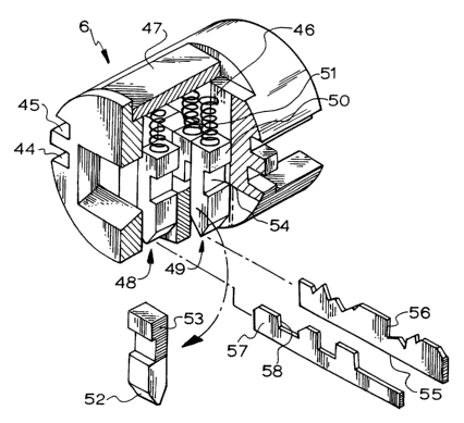
A lock of the type in which a latch means is able to be actuated if elongated
members are able to pass through associated slots (54) in latch elements.
There are two sets of latch elements (50) in two keyways (48, 49) such that,
when the slots (54) in opposed pairs of elements are aligned, the actuating
members can pass through. One set of latch elements (54) are positioned by a
setter or biscuit (56) and the other set are positioned by a key (58) that
corresponds to the shape of the setter to align the slots (54) of
corresponding elements in each set. This type of lock is improved by providing
at least one latch element (50) in one set (ie in one keyway 48 or 49), with a
wider slot (54) to enable master keying. The master key is set to correspond
to the highest or lowest position in the wide slot.
Cette invention concerne un verrou du type dans lequel un moyen de verrouillage peut être actionné si des éléments de forme allongée peuvent traverser des encoches (54) connexes dans les éléments de verrouillage. On trouve deux ensembles d'éléments de verrouillage (50) dans deux entrées de clé (48, 49) de sorte que lorsque les encoches (54) d'éléments de verrouillage (50) opposés sont alignées, les éléments actionneurs peuvent traverser. Un des ensemble d'éléments de verrouillage (50) est positionné par un dispositif de positionnement (56), l'autre par une clé (58) correspondant à la forme du dispositif de réglage et permet d'aligner les encoches (54) des éléments correspondants dans chaque ensemble. Ce type de verrou marque un progrès dans la mesure où au moins un élément de verrouillage (50) d'un ensemble [tel qu'une entrée de clé (48) ou (49)] présente une fente (54) plus importante pour l'emploi d'un passe-partout. Le passe-partout est réglé pour correspondre à la position la plus haute ou la plus basse dans l'encoche large.
Note: Claims are shown in the official language in which they were submitted.
Note: Descriptions are shown in the official language in which they were submitted.
For a clearer understanding of the status of the application/patent presented on this page, the site Disclaimer , as well as the definitions for Patent , Administrative Status , Maintenance Fee and Payment History should be consulted.
| Title | Date |
|---|---|
| Forecasted Issue Date | Unavailable |
| (86) PCT Filing Date | 2002-10-18 |
| (87) PCT Publication Date | 2003-04-24 |
| (85) National Entry | 2004-04-16 |
| Dead Application | 2006-10-18 |
| Abandonment Date | Reason | Reinstatement Date |
|---|---|---|
| 2005-10-18 | FAILURE TO PAY APPLICATION MAINTENANCE FEE |
| Fee Type | Anniversary Year | Due Date | Amount Paid | Paid Date |
|---|---|---|---|---|
| Registration of a document - section 124 | $100.00 | 2004-04-16 | ||
| Application Fee | $200.00 | 2004-04-16 | ||
| Maintenance Fee - Application - New Act | 2 | 2004-10-18 | $50.00 | 2004-10-18 |
Note: Records showing the ownership history in alphabetical order.
| Current Owners on Record |
|---|
| CYLOCK PTY LTD |
| Past Owners on Record |
|---|
| NUGENT, WALTER JOSEPH |

