Note: Descriptions are shown in the official language in which they were submitted.
CA 02464015 2004-04-16
WO 03/034575 PCT/BE02/00159
1
AN AXIAL FLUX PERMANENT MAGNET GENERATOR/ MOTOR
Field of the invention
[0001] The present invention is related to an axial
flux permanent magnet generator/ motor, for example for use
with internal combustion engines, where this type of
machine is incorporated in the flywheel.
State of the art
(0002] The axial flux permanent magnet generator and
motor has been described in various forms. It consists of a
stator comprising a plurality of coils, and a rotor
20' comprising several permanent magnets, wherein an air gap is
present between stator and rotor. The notion of 'axial
flux' is not always defined in the same way. In this text,
the expression 'axial flux' is related to machines wherein
the flux across the air gap is essentially parallel to the
machine's rotational axis.
[0003] The closest prior art when it comes to this
type of machine has been disclosed in the publication
entitled 'An Axial Flux. Interior PM Synchronous Machine',
by D.H. Kang et al., ICEM 2000, 28-30 August 2000. It
comprises two stators, each made as a single hollow
cylinder with radial slots cut out of one of the ring-
shaped surfaces. The coils are then wound round the radial
extensions left in between the removed slots. The
CA 02464015 2004-04-16
WO 03/034575 PCT/BE02/00159
2
manufacture of such a stator is complex as well as
expensive, especially in small series.
Aims of the invention
[0004] The present invention aims to provide a new
axial flux permanent magnet generator/ motor, with reduced
complexity and cost compared to the prior art, whilst
presenting solutions for problems intrinsic in the
simplified design according to the invention.
Summary of the invention
[0005] The present invention is related to a
permanent magnet electrical generator/ motor comprising a
stator, a rotor, a rotational axis and an air gap between
stator and rotor so that the magnetic flux across said air
gap is essentially oriented along said rotational axis,
said rotor comprising a plurality of locations for placing
permanent magnets or elements of magnetic material to form
rotor poles, said generator/ motor being characterised in
that said stator comprises a first non-magnetic disc and a
plurality of magnetic cores, said cores being attached to
said first disc by attachment means, said cores comprising
coils.
[0006] According to the preferred embodiment, the
generator/ motor of the invention further comprises a
number of flux distribution plates in between the stator
and the rotor, said plates being made of magnetic material.
[0007] These flux distribution plates may be
designed as an inner and an outer flux distribution plate,
made of magnetic material, said plates being present in
between the stator and the rotor, said plates comprising
radial extensions, the extensions of the inner plate
pointing radially outward with respect to the machine's
rotational axis, and the extensions of the outer plate
CA 02464015 2004-04-16
WO 03/034575 PCT/BE02/00159
3
pointing radially inward, so that each extension of said
inner plate is adjacent an extension of said outer plate,
with an air gap in between each pair of said adjacent
extensions. The edges of said air gap, which are formed by
the edges of ~ two adjacent extensions are preferably
parallel to each other.
[0008] The flux distribution plates may be attached
to the rotor, so that each of said extensions covers at
least the area of one permanent magnet location.
[0009] Alternatively, the flux distribution plates
may be attached to the stator, so that each of said
extensions covers at least the area of the cross section
of one leg of a core.
[0010] According to one embodiment, the contour of
said extensions comprises two straight portions, and a
circular portion connecting said two straight portions, so
that two adjacent straight portions of two adjacent
extensions are parallel to each other and at an angle to
any radius of said rotor which is crossing said two
adjacent straight portions.
[0011] Flux distribution plates according to the
invention may comprise adjacent strips of magnetic
material. According to the preferred embodiment, said flux
distribution plates comprise outs through the complete
thickness of the plates, in those parts of the plates which
face the rotor poles.
[0012] According to another embodiment, the rotor
comprises locations which are shaped so that their contour
parallel to the rotor surface comprises two concentric
circular portions and two connecting portions connecting
the end points of said circular portions, wherein two
adjacent connecting portions of two adjacent magnets are
parallel to each other.
CA 02464015 2004-04-16
WO 03/034575 PCT/BE02/00159
4
' [0013] Said means for attaching said cores to said
first disc may comprise L-profiles and bolts.
[0014] A generator/ motor according to the invention
may further comprise a ring of magnetic material, connected
to the rotor on the side opposite the stator. This ring may
also be made of laminated magnetic material.
[0015] A generator/ motor according to the invention
may further comprise a second stator, which is placed
opposite the first stator on the other side of said rotor.
Said second stator may be rotated over an angle around the
rotational axis of said generator/ motor, ~,vith respect to
said first stator.
[0016] A generator/ motor according to the invention
may further comprise at least one electronic converter,
which works in "boost-mode" at low speed and as a rectifier
at high speed.
[0017] The rotor may comprise in every one of said
locations a permanent magnet. Alternatively, the rotor may
comprise a number of permanent magnets and a number of
elements made of magnetic material.
[0018] In another design according to the invention,
the rotor may comprise only elements made of magnetic
material and placed into_said permanent magnet locations,
in such a way that the number of rotor poles is different
from the number of stator poles.
[0019] The cores which are used on the stator may be
U-shaped cores or E-shaped cores.
[0020] In the case of 3 or more phase machine, the
generator/ motor according to the invention preferably
further comprises a ring made of laminated magnetic
material, said ring connecting the cores of said stator.
CA 02464015 2004-04-16
WO 03/034575 PCT/BE02/00159
Short description of the drawings
[0021] Fig. 1 shows a photograph of a partly
assembled stator according to the invention.
[0022) Fig. 2 shows a photograph of a complete rotor
5 according to the invention.
[0023] Fig. 3a and 3b represent overviews of an
axial flux generator/motor according to the invention.
[0024] Fig. 4 represents a first sectional view of
the stator of the invention, as shown in fig. 3a.
[0025] Fig. 5 represents a second sectional view of
the stator of the invention, as shown in fig. 3a.
[0026] Fig. 6 represents a sectional view of the
rotor of the invention, as shown in fig. 3.
[0027] Fig. 7 represents a view of a rotor according
to.a second embodiment of the invention.
[0028] Fig. 8 represents a view of a pair of flux
distribution plates, which comprise cuts.
[0029] Figure 9 represents a view of a ring of
laminated magnetic material, which can be installed on the
stator in case of a 3 or more phase machine.
[0030) Fig. 10 illustrates the rotation of one
stator with respect to the other, in the embodiment of the
invention comprising two stators.
Detailed description of the invention
[0031] The present invention generally presents a
concept for an axial flux permanent magnet generator/
motor, wherein a number of cores 2 are attached onto a disc
1, in order to form the stator. The disc 1 is preferably
circular shaped, but the function of this disc can be
performed by any plate made of a non-magnetic material.
Also, the disc or plate 1 may be made of a magnetic
material, which is covered by an insulation. The photograph
of fig. 1 illustrates a partly assembled stator according
CA 02464015 2004-04-16
WO 03/034575 PCT/BE02/00159
6
' to the invention, comprising six U-cores. The fact that
separate cores are used allows the use of standard cores,
thus leading to a straightforward and inexpensive design.
[0032] The main problem of using such a design
however, resides in the large fluctuation of the air gap
between such a stator and the rotor, which is to be placed
facing the cores on the stator. The rotor will preferably
comprise a number of permanent magnets of a given form, at
equal distances on a circle which is co-axial with respect
to the machine's rotational axis. The large air gap
fluctuation is then being caused by the large open spaces
left in-between adjacent cores 2 on the disc 1, as well as
in between the legs of one core 2, making the changeover
between two adjacent poles difficult. The present invention
solves this problem by providing an extra feature in the
form of means for distributing the flux in an optimal way
across the whole of the air gap's cross section
perpendicular to the machine's rotational axis.
[0033] In order to do this, and according to the
preferred embodiment, the rotor or the stator are equipped
with so-called 'flux-distribution plates', which are
specially shaped plates made of magnetic material, placed
in the path of the axial flux between rotor and stator, and
which allow the change-over fluctuation to be reduced to a
minimum. A possible shape of these plates 28, 29 when
attached to the rotor, are illustrated in fig. 2.
[0034] According to a further embodiment, the
feature of flux distribution is obtained by shaping the
permanent magnets themselves in a pre-defined way.
Detailed description of a preferred embodiment of the
invention
[0035] A preferred embodiment of the machine of the
invention is shown in detail in figure 3a. It concerns a
CA 02464015 2004-04-16
WO 03/034575 PCT/BE02/00159
7
mono-phase disc permanent magnet generator, equipped with
twelve cylinder-shaped permanent magnets 25 and flux-
distribution plates 28,29 on the rotor. Sectional views
indicated in fig. 3 are shown in subsequent figures 4 to 6.
The. stator comprises a disc 1, made of non-magnetic
material, onto which six magnetic cores 2 are attached.
These are U-shaped cores and can be any type of standard
core, made of laminated magnetic material. They are
attached to the disc 1 by a number of L-shaped profiles 3,
bolted onto the disc 1 by bolts 4 and onto the cores 2 by
bolts 5. The cores 2 are attached in such a way that the
upstanding legs are essentially perpendicular to the
disc 1.
[0036] The coils 6 are preferably wound round coil
formers 7, which are then placed on the upstanding legs of
the cores 2. A second~disc 8 is preferably added opposite
the first disc 1, so that both discs take care of the
clamping of the cores with sufficient strength and of the
jamming of the coils in the cores. Rectangular openings are
present in the second disc 8 corresponding to the top
surfaces 9 of the legs of the U-shaped cores.
[0037] The first and second disc (1,8) are held
together by a set of bolts 20, in combination with tubes
21. This assembly is then attached through an additional
set of bolts 23 and tubes 24 to a stationary plate 22,
which represents the structure onto which the machine is
installed.
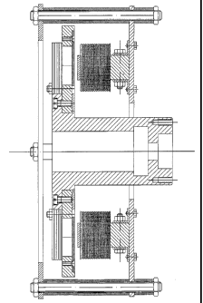
[0038] The rotor ;~ r~c»; t-i nnP~ ; r, hotz.~oo,-, ~
stationary plate 22 and the second disc 8. This rotor
comprises a number of permanent magnets 25 with alternated
orientation of north and south poles. The permanent magnets
are cylinder-shaped. Standard magnets of this type may be
used, such as loudspeaker magnets. The magnets are clamped
into a non-magnetic circular disc 26.
CA 02464015 2004-04-16
WO 03/034575 PCT/BE02/00159
8
[0039] At the back of this non-magnetic disc 26, the
permanent magnets are connected by a ring 27 of magnetic
material, in order to create a magnetic path. On the
surface directly facing the stator, the rotor is equipped
with two flux distribution plates 28 and 29. These are best
illustrated in figure 6 and on the photograph of fig. 2.
In figure 6, the magnets 25 are made visible, for clarity's
sake. The flux distribution plates are made of magnetic
material. Each plate is essentially a ring-shaped disc with
radial extensions covering one type (north or south) of
magnetic pole. The inner plate 28 is attached by bolts 30
to the rotor disc 26 and comprises radial extensions 31,
which are pointing outward from the central ring into which
the bolts 30 are present. Each of these extensions 31
covers the complete area of one type of permanent magnet.
The outer plate 29 is equally bolted by bolts 32 to the
rotor disc 26, and comprises radial extensions 33 which are
pointing inward from the circumferential ring where the
bolts 32 are present. The extensions 33 are covering the
area of the remaining magnets, in between the magnets which
are already covered by the inner plate 28. The surface of
the extensions 31,33 is preferably larger than the surface
of the magnets which they cover.
[0040] The specific contour of the extensions in
this preferred embodiment can be seen to comprise two
straight portions 40 and a circular portion 41, essentially
concentric with the rotor. The straight portions 40 are not
oriented along a radius of the rotor, but are at an angle
to any rotor radius crossing said straight portions. As a
consequence, the air gap 34 between two adjacent extensions
is at an angle to the rotor radius. The reason for this is
explained after this.
[0041] Every extension 31 of the inner plate 28 is
adjacent an extension 33 of the outer plate 29. The air gap
CA 02464015 2004-04-16
WO 03/034575 PCT/BE02/00159
9
34 between these flux distribution plates is larger than
the air gap between the flux distribution plates and the
magnetic material of the stator, in order to avoid flux
lines crossing the air gap between flux distribution
plates.
[0042] The function of these flux distribution
plates is to mitigate the effect of the large fluctuation
in air gap volume, as a consequence of the use of separate
U-cores on the stator, which might otherwise lead to the
problem of torque pulsation (togging). For this purpose,
the area of the extensions 31,33 is as. large as possible,
with the limitation that the air gap 34 between adjacent
extensions needs to be larger than the air gap between
rotor and stator. Furthermore, the air gap 34 between the
flux distribution plates 28 and 29 is designed at an angle
to the radius of the rotor, as a further measure against
torque pulsation. This way, the changeover between two
poles with different orientation can take place with a
minimal variation in air gap volume between the flux
distribution plates and the magnetic material of the
stator.
[0043] The rotor disc is attached to a central part
35, which is to be connected to the machine axis. The
connection between this central part and the rotor disc is
supplied by bolts 36.
Alternative embodiments of the invention
[0044] Figure 3b shows a slightly modified
embodiment which is essentially equivalent to the one shown
in-figure 3a, and wherein the second disc 8 has been
omitted, along with the bolts 20 and tubes 21. In this
embodiment, the clamping of the coils onto the cores is
done by other attaching means, preferably by gluing the
coils 6 to the cores 2.
CA 02464015 2004-04-16
WO 03/034575 PCT/BE02/00159
[0045] The flux distribution plates may be attached
to the stator, facing the rotor, instead of to the rotor.
The same form of plates may be used in this case. The
effect obtained by these plates, put onto the stator is
5 exactly the same as in the above described case. Each
extension 31 or 33 of one of both plates then covers at
least the area of the cross-section of one leg of a core 2.
(0046] The form of flux distribution plates is not
limited to the one shown in the figures. The main
10 characteristic of such a plate is that it essentially
covers at least the area of one rotor or stator pole . It
is also possible to provide a separate flux distribution
plate for every rotor pole.
L0047] The magnet arrangement is not necessarily
based on a series of alternating north and south-oriented
permanent magnets, but may also be based on groups of
north-oriented magnets adjacent to groups of south-oriented
magnets. This is the preferred case for example in a 3 or
more phase machine according to the invention. One rotor
pole then comprises a group of similarly oriented magnets.
In this case therefore, flux distribution plates installed
on the rotor may have fewer but larger extensions 31,33
which cover such a group of adjacent magnets of the same
orientation. Alternatively, separate flux distribution
plates may be installed, each covering one rotor pole.
[0048] The flux may also be distributed in the same
way by shaping the permanent magnets themselves in a given
way. This effect is obtained by using magnets which have
the shape of the radial extensions (31,33) of the flux
distribution plates 28 and 29. A rotor of this kind,
equipped with specially shaped magnets 45 is shown in
figure 7. These magnets are then equally clamped into a
non-magnetic disc 26. No flux distribution plates are
required in this embodiment. The magnets of figure 7 have
CA 02464015 2004-04-16
WO 03/034575 PCT/BE02/00159
11
two concentric circular portions 50 and two connecting
portions 51 between the end points of said circular
portions. In this case, the connecting portions 51 are
straight lines, which are not parallel to the rotor radius,
in order to avoid torque pulsation.
[0049] For both the latter embodiment, as the one
with flux distribution plates, it is not required that the
adjacent edges of the extensions 31,33 or of the magnets 45
are straight lines. These edges may have any shape. It is
however preferred that adjacent edges are parallel.
[0050] In order to adapt it to a 3 or more phase
machine, the rotor of figure 7 may also comprise a smaller
number of larger magnets 45, equally comprising portions
50, 51 but each taking up~a larger space in the rotor's
circumference.
[0051] Instead of U-shaped cores, E-shaped cores may
be used.
[0052] In the machine shown in figure 3, it is not
necessary to use permanent magnets in every position 25.
It is also possible to have a rotor wherein every second
position is filled by a permanent magnet. This may be a
solid permanent magnet or a permanent magnet made of
laminated material. For example, all magnets having their
north pole at the left in figure 3 may be replaced by a
disc made of magnetic material, preferably laminated
magnetic material. Because it is not required to have
permanent magnets at every position 25 around the rotor, as
shown in figure 6, these positions may more generally be
called 'locations', to be filled in either by permanent
magnets or by elements of laminated magnetic material of
the same or other shape as the permanent magnets.
[0053] The ring 27 at the back of the rotor is
preferably formed of a laminated material.
CA 02464015 2004-04-16
WO 03/034575 PCT/BE02/00159
12
[0054] To limit the magnetic losses in the flux
distribution plates 28,29 these plates or at least part of
these plates preferably comprise 'interruptions'
perpendicular to the plate's plane surface. In general, the
plate may be said to comprise a series of adjacent strips
of magnetic material, lying next to each other, and thereby
making up the plate or a part of the plate.
[0055] In the preferred embodiment, the plates are
machined, for example by a laser tool, in order to form
cuts 37 which go through the complete thickness of the
plates and which are located at least in those parts of the
plate facing the rotor poles, see figure 8. Parts on either
side of such a cut 37 are understood to be the 'adjacent
strips' in the more general~description.
[0056] In a special design for the 3 or more phase
machines the magnetic cores of the stator can be
magnetically combined by layered rings of magnetic
material. Figure 9 shows such a layered ring 52, comprising
open spaces 53 which are to be placed over the cores 2 on
the stator. The ring 52 is then placed in between the disc
1 and the coil formers 7.
[0057] For the 3 or more phase system, a special
rotor construction cam be made so that the machine works as
a switched reluctance motor or generator without the use of
permanent magnets on the rotor. All of the rotor poles can
then be built by elements of magnetic material, preferably
laminated, with a special design resembling the radial
extensions 31, 33 in order to produce the same effect as
with the flux distribution plates, or by preferably
laminated magnetic elements, equipped with flux
distribution plates as described above. For the switched
reluctance machine the pole number of the rotor differs
from the pole number of the stator. The equilibrium
CA 02464015 2004-04-16
WO 03/034575 PCT/BE02/00159
13
position of the rotor (minimal reluctance) turns with the
alternate excitation of the different stator poles.
[0058] It is also possible to make a twin type of
machine by replacing the stator construction at the front
of ,the rotor by two similar stator constructions one at
each side of the rotor. For this design, the rotor does not
need the magnetic ring 27 at the backside since the
magnetic path is already closed at each side of the rotor
by the magnetic cores of the stator. The flux distribution
plates 28,29 however or the special design of the permanent
magnets have to be present at both sides of the rotor for
this construction. According to the preferred embodiment,
the stators are rotated over an angle with respect to each
other, around the rotational axis, as is illustrated in
figure 10. This is preferred in order to reduce torque
pulsations.
[0059] The machine can only generate a controlled
output voltage if an electronic converter is being used.
The converter works in "boost-mode" at low speed and as a
rectifier at high speed. For the 3-phase construction, the
electronic converter has the additional function of motor
control when the machiwe is used as a motor.
[0060] It is possible to generate a 3-phase output
with the 1-phase construction by using 3 electronic
converters each on a 1-phase output.
[0061] To reduce the weight of the machine, it is
possible to make the coils 6 of the stator with aluminium
foil instead of with copper wire.