Note: Descriptions are shown in the official language in which they were submitted.
CA 02464052 2004-04-16
WO 03/050008 PCT/US02/36176
CLOSURE WITH
PRESSURE-ACTUATED VALVE AND LID SEAL
TECHNICAL FIELD
This invention relates to a system for dispensing a fluent material from a
container. The invention is particularly suitable for incorporation in a
dispensing closure for use with a squeezable container.
BACKGROUND OF THE INVENTION
AND
TECHNICAL PROBLEMS POSED BY THE PRIOR ART
There are a wide variety of packages which include (1) a container,
(2) a dispensing system extending as a unitary part of, or attachment to, the
container, and (3) a product contained within the container. One type of
such a package employs one or more dispensing valves for discharging one
or more streams of product (which may be a gaseous, liquid, cream, powder,
or particulate product). See, for example, U.S. Patent No. 5,271,531 and
6,112,951. The valve is a flexible, resilient, self-sealing, slit-type valve
at
one end of a bottle or container which typically has resiliently flexible
sidewalls which can be squeezed to pressurize the container interior. The
valve is normally closed and can withstand the weight of the product when
the container is completely inverted, so that the product will not leak out
unless the container is squeezed. When the container is squeezed and the
interior is subjected to a sufficient increased pressure so that there is a
predeterinined minimum pressure differential across the valve, the valve
opens.
In the preferred embodiment, the valve stays open, at least until the
container pressure drops below a predetermined value. Such a valve can be
designed to snap closed if the pressure differential across the open valve
drops below a predetermined amount. The valve can also be designed to
open inwardly to vent air into the container when the pressure within the
container is less than the ambient external pressure, and this accommodates
CA 02464052 2004-04-16
WO 03/050008 PCT/US02/36176
-2-
the return of the resilient container wall from an inwardly squeezed condition
to the normal, unstressed condition.
Such a resilient valve typically includes a central head portion which
is recessed inwardly from surrounding portions of the valve which project
outwardly. The U.S. Patent No. 6,112,951 illustrates such a valve mounted
in the dispensing opening of a closure body to which is hingedly attached a
lid having a post 90 for projecting downwardly toward the valve head when
the lid is closed. Sometimes, when a lid is closed on a closure on a
container which is subjected to external forces, such as may be encountered
during packing, shipping, and handling, and such external forces can
temporarily increase the container internal pressure by squeezing in a portion
of the container wall. The increased pressure within the container may cause
the valve central head portion to move outwardly. If unrestrained, the
outwardly moving central head portion of the valve eventually opens, and a
small amount of the product from the container might be forced through the
open valve. In order to eliminate, or at least minimize, such undesirable
occurrences, the lid post prevents the valve central head from moving
outwardly far enough to open. Rather, the valve central head portion, as it
begins to move outwardly owing to an increased internal pressure, contacts
the lid post before the valve slits can open. Thus, the valve remains sealed
in such over-pressure situations.
While the use of a lid seal post functions generally satisfactorily in
applications in which it is employed, a closure incorporating a lid seal post
in the lid necessarily adds complexity to the lid structure. The more
complex lid structure requires a more complex mold and molding technique.
A requirement to include a seal post in a lid can inhibit the closure
designer's design flexibility with respect to lid style, and with respect to
the
incorporation of other, unrelated features.
CA 02464052 2004-04-16
WO 03/050008 PCT/US02/36176
-3-
It would be desirable to provide a means for preventing the opening
of a flexible valve in a closure during over-pressure conditions without
requiring the use of a projecting seal post on the lid.
- Further, it would be desirable if such an improved means for
preventing the opening of a valve during over-pressure conditions could also
generally function as a leak-proof seal for a package on which the valve-
containing closure is provided.
An improved closure having a flexible valve and a lid without a seal
post should also preferably accommodate a variety of lid designs that could
provide other, desirable features.
It would also be beneficial if an improved dispensing closure system
could readily accommodate its manufacture from a variety of different
materials.
It would also be advantageous if such an improved closure system could
accommodate bottles, containers, or packages which have a variety of shapes
and which are constructed from a variety of materials.
Further, it would be desirable if such an improved system could
accommodate efficient, high-quality, high-speed, large volume manufacturing
techniques with a reduced product reject rate to produce products having
consistent operating characteristics unit-to-unit with high reliability.
BRIEF SUMMARY OF THE INVENTION
The present invention provides an improved dispensing closure system
for a container that has an opening to the container interior. The user can
easily operate the closure system to assume a closed configuration for
preventing flow from the container or to assume an open configuration for
permitting flow from the container.
The present invention provides an improved dispensing closure system
that includes a closure body and a lid, preferably hingedly attached to the
closure body, wherein the lid does not have any outwardly projecting seal
post.
This allows the lid to be more easily molded with less complex mold
structures.
In particular, the lid can be molded at an angle relative to the closure body
top
CA 02464052 2004-04-16
WO 03/050008 PCT/US02/36176
-4-
deck as a generally planar member to accommodate ease of molding and to
reduce the complexity of the mold assembly.
According to a preferred embodiment of the invention, a dispensing
closure system is provided for a container that has an opening to the
container
interior where a product may be stored. The dispensing closure system
comprises a body extending from the container at the opening, and the body
includes a deck defining an aperture. The closure system also further
comprises
a lid movable between a closed position confronting the deck and an open
dispensing position moved away from the closed position. The dispensing
closure system further comprises a dispensing valve disposed with respect to
the
body at the deck aperture.
The dispensing valve includes (a) a marginal portion sealingly engaged
with the body and retained at the body, and (b) a head portion that (1) is
laterally inwardly of the marginal portion, (2) has an exterior side for
interfacing
with the ambient environment, and (3) has an interior side for interfacing
with
the product. Further, the valve head portion includes a normally closed
orifice
which opens to permit flow therethrough in response to a pressure differential
across the valve.
The valve also includes a resilient, flexible, connector sleeve having an
interior surface for interfacing with product and having an exterior surface
for
interfacing with the ambient environment. The connector sleeve has (1) a first
leg connected with the marginal portion, (2) a second leg connected with the
head portion to locate the head portion spaced laterally inwardly of the first
leg
to facilitate outward movement of the head portion when dispensing product
form the container, and (3) an arcuate junction portion joining the first and
second legs. The arcuate junction portion has a generally outwardly
protruding,
convex configuration when viewed from outside of the closure body. The valve
is positioned on the closure body so that the junction portion of the
connector
sleeve projects from the deck aperture beyond at least a portion of the deck
when the valve orifice is closed but the lid is in the open dispensing
position.
The arcuate junction has a generally outwardly facing surface for being
engaged
CA 02464052 2009-05-05
23158-1841
- 5 -
by the lid to elastically deform the junction portion inwardly when the lid is
in the
closed position. This prevents the connector sleeve from rolling far enough
outwardly with the head portion to a position where the valve orifice would
open
when subjected to a sufficient pressure differential.
The closure system can be readily incorporated as a separate
assembly of components defining a closure that is separate from, but which is
adapted to be mounted to, the container. Such a closure may be incorporated in
an embodiment which is removably attachable to the container or which is non-
removably attachable to the container.
According to another aspect of the invention, there is provided a
dispensing closure system for a container that has an opening to the container
interior where a product may be stored, said dispensing closure system
comprising: a body for extending from said container at said opening, said
body
including a deck defining an aperture; a lid movable between a closed position
confronting said deck and an open dispensing position moved away from said
closed position; and a dispensing valve disposed with respect to said body at
said
deck aperture, said valve having an unactuated, retracted configuration
defining a
rest position, said valve including: (a) a marginal portion sealingly engaged
with
said body and retained at said body; (b) a head portion that (1) is laterally
inwardly
of said marginal portion, (2) has an exterior side for interfacing with
ambient
environment, and (3) has an interior side for interfacing with the product,
said
head portion including a normally closed orifice when said valve is in said
rest
position and which opens to permit flow therethrough in response to a pressure
differential across said valve; and (c) a resilient, flexible, connector
sleeve having
an interior surface for interfacing with the product and having an exterior
surface
for interfacing with ambient environment, said connector sleeve having (1) a
first
leg connected with said marginal portion, (2) a second leg connected with said
head portion to locate said head portion spaced laterally inwardly of said
first leg
when said valve is in said rest position to facilitate outward movement of
said
head portion when dispensing product from the container, and (3) a junction
portion joining said first and second legs, said junction portion being
arcuate and
having a generally outwardly protruding, convex configuration when viewed from
CA 02464052 2009-05-05
23158-1841
- 5a -
outside of said body when said valve is in said rest position, characterized
in that
said valve is positioned on said body when said valve is in said rest position
so
that said junction portion projects from said deck aperture beyond at least a
portion of said deck when said valve orifice is closed but said lid is in said
open
dispensing position, said junction portion having a generally outwardly facing
surface for being engaged by said interior side of said lid when said valve is
in
said rest position to elastically deform said junction portion inwardly when
said lid
is in said closed position thereby preventing said connector sleeve from
rolling far
enough outwardly with said head portion to a position where said valve orifice
lo would open when subjected to a sufficient pressure differential.
Numerous other advantages and features of the present invention
will become readily apparent from the following detailed description of the
invention, from the claims, and from the accompanying drawings.
BRIEF DESCRIPTION OF THE DRAWINGS
In the accompanying drawings that form part of the specification,
and in which like numerals are employed to designate like parts throughout the
same,
FIG. 1 is a fragmentary, perspective view of an exemplary
dispensing closure system in the form of a separate dispensing closure
according
to a preferred embodiment of the invention, and the closure is shown in an
open
configuration prior to closing the lid and installing the closure on a
container (not
illustrated), and the closure is shown from a vantage point generally above,
or
from the top of, the closure;
FIG. 2 is an exploded, perspective view of the closure illustrated in
FIG. 1;
FIG. 3 is a cross-sectional view of the closure body taken generally
along the plane 3-3 in FIG. 2;
FIG. 4 is a greatly enlarged, cross-sectional view of the valve taken
generally along the plane 4-4 in FIG. 2;
CA 02464052 2009-05-05
23158-1841
- 5b -
FIG. 5 is a view similar to FIG. 4, but FIG. 5 shows the valve opening
when subjected to a pressure differential across the valve;
FIG. 6 is a greatly enlarged, fragmentary, cross-sectional view of the
portion of the closure containing the closure body dispensing orifice and
valve
CA 02464052 2004-04-16
WO 03/050008 PCT/US02/36176
-6-
disposed therein, said cross-sectional view being taken along the plane 6-6 in
FIG. 1;
FIG. 7 is a cross-sectional view similar to FIG. 6, but FIG. 7 shows the
entire closure and shows the lid in the fully closed position, and FIG. 7 also
shows the closure installed on the neck of a container, a fragmentary portion
of
which container neck is visible in FIG. 7;
FIG. 8 is a view similar to FIG. 7, but FIG. 8 omits the container neck
so as to reveal structure details of the container mounting portion regions of
the
closure body; and
FIG. 9 is a greatly enlarged, fragmentary, cross-sectional view of the
closure body dispensing orifice and valve similar to FIG. 6, but FIG. 9 shows
the lid in a fully closed position.
DETAILED DESCRIPTION
While this invention is susceptible of embodiment in many different
forms, this specification and the accompanying drawings disclose only one
specific form as an example of the invention. The invention is not intended to
be limited to the embodiment so described, however. The scope of the
invention is pointed out in the appended claims.
For ease of description, most of the figures illustrating the invention
show a dispensing closure system in the typical orientation that it would have
at
the top of a container when the container is stored upright on its base, and
terms such as upper, lower, horizontal, etc., are used with reference to this
position. It will be understood, however, that the dispensing closure system
of
this invention may be manufactured, stored, transported, used, and sold in an
orientation other than the position described.
The dispensing closure system of this invention is suitable for use with a
variety of conventional or special containers having various designs, the
details
of which, although not illustrated or described, would be apparent to those
having skill in the art and an understanding of such containers. In the
illustrated embodiment of the invention described herein, the container, per
se,
as described herein forms no part of, and therefore is not intended to limit,
the
CA 02464052 2004-04-16
WO 03/050008 PCT/US02/36176
-7-
present invention. It will also be understood by those of ordinary skill that
novel and non-obvious inventive aspects are embodied in the described
exemplary closure system alone. In other embodiments that are not illustrated
herein, the closure system could be formed as a unitary part, or non-removable
part, of the container so that the invention could be regarded in such a case
as
including at least the "closure" portion of such a container.
A presently preferred embodiment of a dispensing structure or
dispensing closure system of the present invention in the form of a
dispensing closure assembly is illustrated in FIGS. 1-9 and is designated
generally therein by reference number 20 in FIG. 1. The dispensing closure
assembly 20, which is hereinafter sometimes referred to more simply as the
"closure 20," is, in the preferred illustrated embodiment, provided as a
separately manufactured unit or subassembly for mounting to the top of a
container (not shown in FIG. 1). It will be appreciated, however, that it is
contemplated that in some applications it may be desirable for the dispensing
closure system of the present invention to be formed as a unitary part, or
extension, of a container.
The container typically has a conventional mouth or opening which
provides access to the container interior and product contained therein. The
product may be, for example, a beverage such as water, or other liquid
comestible product. The product could also be any other fluent material,
including, but not limited to, gases, powders, particles, and liquids
(including
creams, lotions, slurries, pastes, etc.). Such materials may be sold, for
example,
as a food product, a personal care product, an industrial or household
product,
or other composition (e.g., for internal or external use by humans or animals,
or
for use in activities involving medicine, manufacturing, commercial or
household maintenance, construction, agriculture, etc.).
The container may typically have a neck or other suitable structure
defining the container mouth. The neck may have (but need not have) a
circular cross-sectional configuration, and the body of the container may have
another cross-sectional configuration, such as an oval cross-sectional shape,
for
CA 02464052 2004-04-16
WO 03/050008 PCT/US02/36176
-8-
example. The container may, on the other hand, have a substantially uniform
shape along its entire length or height without any neck portion of reduced
size
or different cross-section.
The container may typically be a squeezable container having a flexible
wall or walls which can be grasped by the user and compressed to increase the
internal pressure within the container so as to squeeze the product out of the
container through the closure 20 when the closure 20 is open. Such a container
wall typically has sufficient, inherent resiliency so that when the squeezing
forces are removed, the container wall returns to its normal, unstressed
shape.
Such a structure is preferred in many applications, but may not be necessary
or
preferred in other applications. Indeed, the container may be substantially
rigid.
A piston could be provided in such a rigid container to aid in dispensing a
product, especially a relatively viscous product. On the other hand, a rigid
container could be employed for inverted dispensing of the contents solely
under
the influence of gravity and/or under the influence of a reduced ambient
pressure exterior of the container (e.g., as by sucking on the open closure
20).
In the preferred embodiment illustrated in FIG. 7, the dispensing
closure system of the present invention is provided in the form of a closure
which is adapted to be mounted on a container 22 (partially illustrated in
20 FIG. 7). The container 22 could include a body portion or body having an
upwardly extending neck 26 as shown in FIG. 7. The neck 26 defines an
opening 28 to the container interior. The container neck 26, in the preferred
embodiment illustrated in FIG. 7, has an external bead 29 for engaging the
closure 20.
The body of the container 22 below the neck 26 may have any
suitable configuration, and the upwardly projecting neck 26 may have a
different cross-sectional size and/or shape than the container body.
Alternatively, the container 22 need not have a neck 26 per se. Instead, the
container 22 may consist of just a body with an opening. The container 22
CA 02464052 2004-04-16
WO 03/050008 PCT/US02/36176
-9-
may have a rigid wall or walls, or may have a somewhat flexible wall or
walls.
Although the container, per se, does not necessarily form a part of the
broadest aspects of the present invention, per se, it will be appreciated that
at
least a lower portion of the dispensing structure, system, or closure 20 of
the
pres,ent invention may be provided as a unitary portion, or extension, of the
top of the container 22. However, in the preferred embodiment illustrated,
the dispensing system or closure 20 is a separate element or assembly (e.g., a
closure) which is adapted to be removably or non-removably mounted to a
previously manufactured container 22 which has an opening 28 to the
container interior.
It is presently contemplated that many applications employing the closure
will be most conveniently realized by molding some or all of the
components of the closure 20 from a suitable thermoplastic and/or thermoset
15 material or materials. The closure components may be separately molded from
the same material or from different materials. The materials may have the same
or different colors and textures.
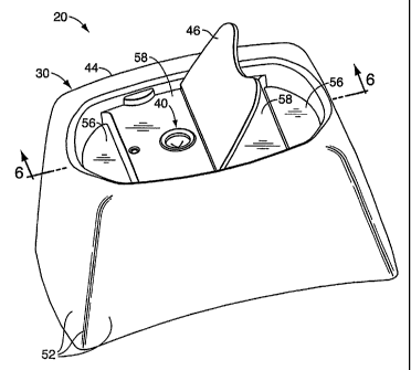
As can be seen in FIG. 2, the illustrated preferred embodiment of the
closure system 20 includes three basic components, (1) a housing 30, (2) a
20 valve 40 which is adapted to be carried on the housing 30, and (3) a
retainer 42
for securing the valve 40 in the housing 30. As can be seen in FIG. 3, the
housing 30 is a unitary structure having a body 44, a lid 46, and a hinge 48
connecting the lid 46 to the body 44. The hinge 48 accommodates movement
of the lid 46 between an as-molded open position illustrated in FIGS. 1-3 and
a
fully closed position illustrated in FIGS. 7 and 8.
As can be seen in FIG. 3, the closure housing 30 includes a skirt 52.
As shown in FIG. 7, the skirt 52 is configured to surround, and extend
downwardly around, an upper portion of the container neck 26 when the closure
20 is properly mounted on the container 22. As shown in FIG. 7, an internal,
peripheral wall extends downwardly from the upper edge of the skirt 52 and
CA 02464052 2004-04-16
WO 03/050008 PCT/US02/36176
-10-
defines a peripheral rim 54. The bottom of the rim 54 terminates at a
generally
horizontal deck 56. In the central region of the deck 56, there is a raised
platform 58. The platform 58 is a unitary extension of the deck 56 and
therefore may be characterized as, or regarded as, a part of the deck 56.
As shown in FIG. 2, adjacent portions of the rim 54 and deck 56 define
openings or apertures 59A, and a tab 59B projects outwardly from the rim 54
over each aperture 59A. Preferably, there are at least two such tabs 59B, one
on each side of the closure body 44, for holding the lid 46 in the closed
position with a snap-fit engagement (FIGS. 7 and 8). To this end, the upper
surface of each tab 59B is convex (as viewed from above the closure body 44
in FIG. 2), and the tab surface curves downwardly toward the deck platform 58.
When the lid 46 is moved toward the closed position, the bottom edge
of the lid 46 engages the convex surface of each tab 59B. Owing to the
resiliency of the closure body 44, the tabs 59B and/or the rim 54 can
temporarily deform or deflect outwardly a sufficient amount to accommodate the
movement of the lid 46 past the tabs 59B to the fully closed position on the
deck platform 58 as illustrated in FIGS. 7 and 8.
After the lid 46 has moved or snapped downwardly past the tabs 59B,
the tabs 59B move from the temporarily outwardly deflected positions back to
the normal, unstressed positions, so that an outer portion of each tab 59B
extends over, and confronts, a marginal portion of the lid 46 to thereby
retain
the lid 46 in the closed configuration (FIGS. 7 and 8).
Extending downwardly from, and below, the deck 56 (FIG. 7) is a
generally annular wall 60. Near the bottom edge of the wall 60 is an inwardly
projecting snap-fit bead 62 which is adapted to engage the lower edge of the
container neck bead 29 as shown in FIG. 7. The wall 60 is sufficiently
resilient
to accommodate a snap-fit engagement which permits the bead 62 to initially
slide against, then downwardly beyond, the edge of the container neck bead 29
so that the bead 62 then moves inwardly owing to the resiliency of the wall 60
to effect a snap-fit engagement between the bead 62 and container neck bead 29
as shown in FIG. 7.
CA 02464052 2004-04-16
WO 03/050008 PCT/US02/36176
-11-
Alternatively, the closure wall 60 could be provided with some other
container connecting means, such as a groove (not illustrated) or a thread
(not
illustrated) for engaging a container neck thread (not illustrated). The
closure
housing 30 could also be permanently attached to the container 22 by means of
induction melting, ultrasonic melting, gluing, or the like, depending on
materials
used for the closure housing 30 and container 22. The closure housing 30 could
also be formed as a unitary part, or extension, of the container 22.
The closure body skirt 52 and wall 60 may have any suitable
configuration for accommodating an upwardly projecting neck 26 or other
portion of the container 22 received within the particular configuration of
the
closure body 30, and the main part of the container 22 may have a different
cross-sectional shape than the container neck 26 and closure body housing.
Also, if desired, and as shown in FIG. 7, the closure body 44 may be
provided with an annular seal 64 extending downwardly from the underside of
the closure body deck platform 58 for sealingly engaging the container neck
26.
Such a seal 64 could be a plug seal as shown, or a "crab's claw" profile seal,
or some other such seal, depending upon the particular application.
With continued reference to FIG. 3, the closure body 44 also includes a
reduced diameter, annular wall 70. At the lower end of the wall 70, there is
an
inwardly extending lip or bead 72 for engaging the retainer 42.
As can be seen in FIG. 2, the closure housing body platform 58 on the
deck 56 defines an aperture 76. As can be seen in FIG. 6, the aperture 76 is
adapted to receive the valve 40 which is held in position against the platform
58 by the retainer 42. As shown in FIG. 2, the retainer 42 has a generally
annular configuration with a peripheral snap-fit bead 80. The snap-fit bead 80
is adapted to be engaged by the closure body bead 72 as shown in FIG. 6. The
closure body wall 70 from which the closure body bead 72 projects is
sufficiently resilient to accommodate temporary outward expansion or
deflection
as the retainer 80 is pushed upwardly within the wall 70. The bead 72 is
configured with an appropriate tapered surface so that the retainer bead 80
can
slide along the bead 72 upwardly and then past the bead 72 until the
resiliency
CA 02464052 2004-04-16
WO 03/050008 PCT/US02/36176
- 12-
of the wall 70 causes a bead 72 to snap back inwardly beneath the retainer
bead
80 in a secure, snap-fit engagement.
As can be seen in FIG. 6, the upper portion of the retainer 42 has a
frustoconical, tapered surface 82 for engaging a peripheral portion of the
valve
40. As shown in FIG. 6 around the periphery of the closure body aperture 76,
the deck 58 includes a downwardly projecting portion defining a frustoconical
or tapered seating surface 86. The seating surface 86 cooperates with the
retainer surface 82 to clamp the peripheral portion of the valve 40 in a seal-
tight
engagement within the closure housing 30.
The peripheral portion of the valve 40 may be characterized as a flange
88 having a generally dove-tail configuration when viewed in vertical cross
section as shown in FIG. 6.
In alternate embodiments (not illustrated), the valve flange 88 could have
other shapes, and the valve 40 could be retained within the closure system 20
in
other ways. For example, instead of including the separate retainer 42, the
closure system 20 could instead employ merely a deformable annular wall
similar to the wall 70 that is unitary with, and projects downwardly from, the
underside of the closure body platform 58. Such a deformable wall could be
deformed or crimped against the valve flange to hold the valve in place.
The valve 40 is preferably molded from an elastomer, such as a synthetic
thermosetting polymer, including silicone rubber, such as the silicone rubber
sold by Dow Coming Corp. in the United States of America under the trade
designation DC 94-595HC. However, the valve 40 can also be molded from
other thermosetting materials or from other elastomeric materials, or from
thermoplastic polymers or thermoplastic elastomers, including those based upon
materials such as thermoplastic propylene, ethylene, urethane, and styrene,
including their halogenated counterparts.
As shown in FIG. 4, valve 40 includes, in addition to the marginal
portion or flange 88, a valve head 90 with a discharge orifice 92 therein, and
a connector sleeve 94 which has one end connected with valve flange 88 and
CA 02464052 2004-04-16
WO 03/050008 PCT/US02/36176
- 13 -
the opposite end connected with the valve head 90 adjacent a marginal or
peripheral surface thereof.
The connector sleeve 94 has a resiliently flexible construction, such
that when pressure within a container is increased sufficiently, valve head 90
shifts outwardly to a fully extended position (FIG. 5) where the valve 40
becomes fully opened to accommodate discharge of the container contents.
With reference to FIG. 4, the illustrated dispensing valve 40 has an
integrally formed or unitary, one-piece construction. The valve 40 is
preferably molded from a resiliently flexible material, and in the illustrated
example the material comprises a silicone rubber which is substantially inert
so as to avoid reaction with, and/or adulteration of, the product being
packaged. In one contemplated method of manufacturing the valve 40 of the
present invention, the valve 40 is produced at relatively high speeds by the
molding of liquid silicone rubber.
In the illustrated preferred embodiment, the marginal flange 88 of the
valve 40 has an annular plan shape, and the valve flange 88 has a
substantially dove-tail cross-sectional configuration with an outer or first
frustoconical surface 100, and an inner or second frustoconical surface 102.
The marginal valve flange 88 has substantial thickness between the outer, or
first, frustoconical surface 100 and the inner, or second, frustoconical
surface
102 which is resiliently compressed by the retainer 42 upon mounting the
valve 40 in the closure so as to form a secure leak-resistant seal
therebetween.
The valve 10 has a head portion 90 (FIG. 4), which has a circular plan
shape, and a generally tapered construction which is thicker at the radially
outside portion of the valve head 90, and thinner at the radially inside
portion
thereof. This tapered construction assists in achieving the snap open action
of
the valve 40, as described below. More specifically, in the illustrated
example, valve head 90 has an exterior side or surface 106 for interfacing
with the ambient environment. The exterior surface 106 has an arcuately
shaped side elevational configuration which opens or curves outwardly,
CA 02464052 2004-04-16
WO 03/050008 PCT/US02/36176
- 14 -
toward the exterior of a container, and the surface 106 is defmed by first,
predetermined radius. The valve head exterior surface 106 extends
continuously to the connector sleeve 94 which in turn extends from the
periphery of the head 90 to the marginal portion or flange 88.
The valve head 90 also includes an interior side or surface 108 (FIG.
4) for interfacing with the product in a container. The valve head interior
side surface 108 has a marginal portion 110 with an arcuately shaped side
elevational configuration which opens or curves outwardly, toward the exterior
of a container, and is defined by a second predetermined radius. The radius
of the marginal portion 110 on interior surface 108 is larger than the radius
of
the exterior surface 106, such that the two surfaces converge toward the
center of the valve head 90 at the center of the orifice 92, and provide the
above-noted inwardly tapered construction of the valve head 90. The exterior
surface radius and the interior surface radius may each be characterized as a
spherical radius.
The interior surface 108 of the valve head 90 also includes a center
portion or planar central area 112, which has a circular plan shape, with a
substantially planar or flat side elevational configuration, oriented
generally
perpendicularly to the discharge orifice 92. The intersection of the valve
head
marginal portion 110 and planar central portion 112 of the valve head 90
defines a circular locus 114. The planar central portion 112 of the valve head
90 assists in improving the opening characteristic of the valve 40, as set
forth
below.
In the illustrated embodiment as shown in FIG. 4, the outer perimeter
of the valve head 90 is preferably defined by a slightly tapered peripheral
surface or marginal surface 120 which begins at a peripheral outer edge 122
of the head marginal portion 110, and extends outwardly therefrom with a
slight taper, ultimately merging into the connector sleeve 94. The edge 122
may be characterized as a circular, peripheral edge. The outside diameter of
valve head 90, as measured along peripheral edge 122, is substantially smaller
CA 02464052 2004-04-16
WO 03/050008 PCT/US02/36176
- 15 -
than the inside diameter of the marginal flange 88. This spacing between the
valve head 90 and the marginal flange 88 permits, among other things, the
valve head 90 to shift freely in an axial direction along the central
longitudinal axis 129 of the marginal flange 88.
In the illustrated preferred embodiment, the valve 40 has a generally
circular configuration about such a cental longitudinal axis 129 which can
also be characterized as a longitudinal axis extending through the valve 40,
and the orifice 92 is defined by a plurality of slits 130 radiating laterally
from
the longitudinal axis 129. Preferably, there are four slits 130. A lesser or
greater number of slits 130 could be used. The slits 130 extend transversely
through head portion 90 from the exterior side or surface 106 to the interior
side or surface 108.
In the illustrated preferred embodiment, the slits 130 extend laterally
from a common origin on the longitudinal axis 129 to define four flaps 132
(FIG. 5) which flex outwardly to selectively permit the flow of product from
a container through the valve 40. Each slit 130 terminates in a radially outer
end. In the illustrated preferred embodiment, the slits 130 are of equal
length, although the slits could be of unequal length.
In the preferred embodiment, each slit 130 is planar and parallel to the
central geometric axis 129 of the valve. Each slit 130 preferably defmes a
linear locus along the head portion exterior side 106 and along the head
portion interior side 108. Preferably, the slits 130 diverge from an origin on
the longitudinal axis 129 and define equal size angles between each pair of
adjacent slits 130 so that the flaps 132 are of equal size. Preferably, four
slits 130 diverge at 90 angles to defme two mutually perpendicular,
intersecting, longer slits. The slits 130 are preferably formed so that the
opposing side faces of adjacent valve flaps 132 closely seal against one
another when discharge orifice 92 is in its normal, fully closed position. The
length and location of the slits 130 can be adjusted to vary the predetermined
opening pressure of the valve 40, as well as other dispensing characteristics.
CA 02464052 2004-04-16
WO 03/050008 PCT/US02/36176
- 16 -
It is to be understood that the orifice 92 may assume many different
shapes, sizes and/or configurations in accordance with those dispensing
characteristics desired. For example, orifice 92 may also include five or more
slits, particularly when larger or wider streams are desired, and/or the
product
is a particulate material or a liquid containing aggregates.
The connector sleeve 94 is in the form of a rolling diaphragm, having
a generally U-shaped cross-section defining an interior surface 140 and an
exterior surface 142 (FIG. 4). The connector sleeve 94 has a first leg 151
(FIG. 4) that is connected with the flange 88, and has a second leg 152 (FIG.
4) that is connected with the head portion 90 of the valve 40. The second
leg 152 is preferably shorter than the first leg 151.
The thickness of each leg may vary, and the thickness of the first leg
151 may be the same as the thickness of the second leg 152. However, in
the illustrated preferred embodiment, the first leg 151 and the second leg 152
are each of substantially uniform thickness, with the first leg 151 being
thicker than the second leg 152. In accordance with a preferred embodiment,
the thickness of first leg 151 is about .015 inches and the thickness of
second
leg 152 is about .007 inches. Other thicknesses could be employed,
depending on the material from which the valve sleeve 94 is constructed, the
type of product to be dispensed, and/or on the overall diameter or size of the
valve.
In the illustrated preferred embodiment, the first leg 151 and second
leg 152 are substantially parallel to one another, and both are oriented
substantially perpendicular to a horizontal plane passing through the valve
head 90. The first leg 151 extends axially outwardly from an inner portion of
the marginal flange 88. The second leg 152 has an end portion that extends
axially outwardly from the marginal portion 110 of the valve head 90 so as to
be generally contiguous with, and merge with, marginal surface 120 of the
valve head 90.
CA 02464052 2004-04-16
WO 03/050008 PCT/US02/36176
- 17-
The connector sleeve 94 locates the valve head 90 so that a horizontal
plane passing through the valve head 90 extends through or outside of the
marginal flange 88. The term "horizontal plane" is used herein with reference
to a vertically oriented dispensing valve 40 as shown in FIG. 4. Such a plane
may also be characterized as a plane that is generally normal or perpendicular
to the valve discharge flow path or direction.
The connector sleeve 94 may also be characterized as having a short,
arcuate junction portion 160 (FIG. 4) joining the long first leg 151 to the
short second leg 152 (which is parallel to the first leg 151 when the valve 40
is in the unactuated configuration (FIG. 4)).
The dispensing valve 40 is preferably configured for use in conjunction
with a particular container, and a specific type of product, so as to achieve
the exact dispensing characteristics desired. For example, the viscosity and
density of the fluid product are both important factors in designing the
specific configuration of the valve 40 for liquids, as is the shape, size, and
strength of the container. The rigidity and durometer of the valve material,
and size and shape of both the valve head 90 and the connector sleeve 94, are
also important in achieving the desired dispensing characteristics, and can be
matched with both the container and the material to be dispensed therefrom.
The valve 40 is suitable for dispensing flowable products, such as
liquids or even gases, powders, particulates, or granular material, as well as
suspensions of solid particles in a liquid. The valve 40 is particularly
suitable
for dispensing shampoos, liquid toothpaste, thin oils, thick lotions, water,
and
the like.
It is to be understood that, according to the present invention, the valve
40 may assume different shapes and sizes, particularly in keeping with the
type of container and product to be dispensed therefrom. The predetermined
opening pressure of the valve 40 may be varied widely in accordance with
those dispensing criteria desired for a particular product. Flow
characteristics
of the dispensed product can also be adjusted substantially, such as for
CA 02464052 2004-04-16
WO 03/050008 PCT/US02/36176
- 18 -
relatively wide column-like streams, thin needle-like streams, multiple
streams,
variations thereof, and the like.
In operation, the valve 40 functions in the following manner. The
valve 40 normally assumes an initial, protruding orientation illustrated in
FIG.
4, wherein the valve 40 remains substantially in its original molded shape
without deformation, with the connector sleeve 94 being substantially
unstressed and the valve discharge opening 92 being fully closed. When the
valve 40 is mounted in the closure 20 as is shown in FIG. 1, the valve 40 is
configured such that discharge orifice 92 will remain securely closed after
the
container is inverted and the lid 46 opened, even under the hydraulic head
pressure applied thereto by the weight of a fluid product when the container
is completely full.
When additional pressure is established in the interior of the container,
such as by manually flexing the container sidewalls inwardly, the connector
sleeve 94 begins to distort, and the valve head 90 begins to shift axially
outwardly.
As the interior of the container is subjected to additional pressure, the
valve head 90 continues to move outwardly until the connector sleeve 94 is
substantially fully extended, as illustrated in FIG. 5. When the valve head 90
is in the substantially fully extended position (FIG. 5), the connector sleeve
94 is highly stressed.
When the interior of the container is subjected to further increased
pressure, the valve head 90, per se, continues to shift outwardly. However,
because connector sleeve 94 is already substantially fully extended, further
outward shifting of the valve head 90 longitudinally tensions or stretches the
connector sleeve 90, thereby increasing the outwardly directed torque applied
to the valve head 90. Also, the further outward movement of the valve head
90 tends to flatten or straighten the valve head 90, particularly along the
exterior surface 106 thereof. This flattening motion tends to slightly enlarge
or dilate the circular plan configuration of the valve head 90, which
CA 02464052 2004-04-16
WO 03/050008 PCT/US02/36176
- 19-
enlargement is in turn resisted by radially inwardly directed forces applied
to
the marginal surface 120 of the valve head 90 by the connector sleeve 94,
thereby generating another complex pattern of stresses within the valve 40,
and these include stresses which tend to compress the valve head 90 in a
radially inward direction. Due to the tapered shape of the valve head 90, the
majority of compression strain is believed to take place adjacent the planar
central portion 112 of the valve head 90.
When additional pressure is applied to the interior of the container, the
valve head 90 continues to shift outwardly by further longitudinal stretching
of the connector sleeve 94, and further enlargement of the plan shape of the
valve head 90. The marginal edge 122 of the valve head 90 is elastically
deformed further inwardly, as a consequence of the increased torque forces
applied thereto by the connector sleeve 94. These combined forces and
motions also serve to further compress the valve head 90 into a state of
bifurcation, wherein the combined forces acting on the valve head 90 will,
upon application of any additional outward force on the interior side 108 of
the valve 40, cause the valve 40 to quickly open outwardly by separating the
valve flaps 132 in the manner illustrated in FIG. 5, and thereby dispense the
product through discharge orifice (typically with the container and closure
turned generally upside down). The valve 40 continues to open to the full
open configuration shown.
The bifurcation state of the valve 40, as the term is used herein,
defines a relatively unstabl`e condition which the valve 40 assumes
immediately prior to the valve flaps 132 starting to open. As the valve 40
passes through the bifurcation state, the combined forces acting on the valve
head 90 are in a temporary, unstable condition of equilibrium, and then
quickly shift the valve head 90 into a generally convex shape, simultaneously
opening the valve flaps 132 to create the open orifice. In the bifurcation
state, the valve head 90 assumes the shape of a nearly planar disc (not
CA 02464052 2004-04-16
WO 03/050008 PCT/US02/36176
- 20 -
illustrated), but with exterior surface 106 cupped and the interior surface
108
bent.
The provision of the first leg portion 151 of the connector sleeve 94 is
such that, during dispensing of product through the open valve 40, the valve
40 extends outwardly of the closure 20 to allow for easier visibility to the
consumer. The configuration of the connector sleeve 94 also minimizes the
catching of dispensed product on the outside of the closure 20, even when the
inverted container is tipped back over to a thirty degree angle from vertical
during dispensing.
The thickness of the valve head 30 and length of the valve slits 130
can be selected so that the open valve either snaps closed when the pressure
differential decreases to a predetermined level or remains fully open even
when the pressure differential drops to zero.
With reference to FIG. 6, it can be seen that when the lid 46 is open
and the valve 40 is in the unactuated, retracted, rest position, the valve
sleeve
94 is situated and configured such that the arcuate junction portion 160 has a
generally outwardly protruding, convex configuration when viewed from
outside the closure body and projects from the deck aperture 76 beyond at
least a portion of the platform 58 which is part of the deck 56 (FIG. 1). The
arcuate junction portion 160 of the valve 40 has a generally outwardly facing
surface for being engaged by the lid 46 to elastically deform the junction
portion 160 inwardly when the lid is in the closed position (FIG. 9). This
prevents the connector sleeve 94 from rolling far enough outwardly with the
head portion 90 to a position where the valve orifice might tend to open
when subjected to a sufficient differential pressure. Because outward
movement of the valve head 90 is prevented by the closed lid 46, the lid 46
need not be provided with a separate seal post projecting downwardly into the
valve 40. Thus, the interior side of the lid 46 can be made generally flat.
As shown in FIG. 3, because the interior surface of the lid 46 can be
generally planar or flat, and because the exterior surface of the lid 46 can
be
CA 02464052 2004-04-16
WO 03/050008 PCT/US02/36176
-21-
generally planar or flat, the lid 46 can be molded as a unitary part of the
closure housing at an oblique angle relative to the closure deck platform 58.
This permits the various structural features of the closure housing 30 to be
readily molded with mold components that can be of relatively simple
construction and which can be employed in the mold assembly without side
action operation. This permits a more simple mold assembly to be employed.
As shown in FIG. 6, the exterior vertical surface of the first leg 151
confronts, and is adjacent, the generally cylindrical sidewall of the closure
body aperture 76. However, it is contemplated that in an alternate
embodiment (not illustrated), there may be an annular gap or space between
the exterior of the first leg 151 and the cylindrical aperture 76.
It will be readily apparent from the foregoing detailed description of
the invention and from the illustrations thereof that numerous variations and
modifications may be effected without departing from the true spirit and
scope of the novel concepts or principles of this invention.