Note: Descriptions are shown in the official language in which they were submitted.
CA 02464212 2004-04-21
WO 03/038567 PCT/US02/35254
DIGITAL AUDIO DEVICE
Cross-Refe~nce to Related Applications
[0001 ] This application is based on and claims priority under
35 U.S.C. ~ 119 from the following co-pending provisional patent applications,
which are incorporated herein by this reference, in their entirety and for all
purposes: PORTABLE DIGITAL DEVICE FOR RECORDING, SHARING,
AND PLAYING AUDIO CONTENT, Serial No. 60/340,616, filed November
l, 2001; and PORTABLE DIGITAL DEVICE FOR RECORDING,
SHARING, AND PLAYING AUDIO CONTENT, Serial No. 60/337,555, filed
November 8, 2001.
Technical Field
[0002] The present invention relates to a digital audio device, and more
particularly, to a digital audio device used to record, share, and play audio
content.
Background of the Invention
[0003] It has become a common practice to store audio content in a
portable format so that individuals may enjoy audio content regardless of
their
location. Portable audio players such as portable radios, portable audio
cassette
players, portable compact disk players, and portable minidisk players have
been used to achieve this purpose.
[0004] Some portable audio devices use digital memory to store the
audio content in an encoded digital format. Known devices that use digital
memory to store audio content include those disclosed in U.S. Patent Nos.
4,518,827; 4,614,144; 4,905,289; 5,914,941; 5,930,758; and 6,076,063, the
disclosures of which are incorporated by reference in their entirety for all
purposes.
CA 02464212 2004-04-21
WO 03/038567 PCT/US02/35254
2/27
Summary of the Invention
[0005] A digital audio device is provided. According to one aspect of
the invention, the device includes a memory and an analog input system
configured to record analog audio signals to the memory as digital audio data.
The device further includes a digital input configured to download digital
audio
data to the memory, as well as an analog output system configured to generate
analog playback signals decoded from digital audio data stored in the memory.
Furthermore, the device includes a digital output configured to upload digital
audio data from the memory.
Brief Description of the Drawings
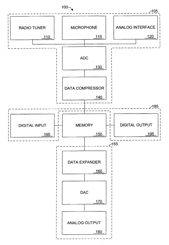
[0006] Fig. 1 is a schematic view of a digital device according to an
embodiment of the present invention.
(0007] Fig. 2 is a plan view of the digital device of Fig. 1.
(0008] Fig. 3 is a back plan view of the digital device of Fig. 1.
(0009] Fig. 4 is a three-dimensional view of a trade connector of the
digital device of Fig. 1.
[0010] Fig. S is an elevation view of two digital devices mated together
to share digital data.
Detailed Description of the Invention
[0011 ] Fig. 1 schematically depicts an embodiment of a digital device
100 capable of recording, sharing, and playing audio content in accordance
with an embodiment of the present invention. As described in more detail
below, the digital device is capable of receiving analog audio signals from a
variety of sources, and the device is capable of storing the received audio
CA 02464212 2004-04-21
WO 03/038567 PCT/US02/35254
3/27
signals in memory as digital audio data. In some embodiments, the audio
signals may be digitally compressed so that the resulting digital audio data
occupies less memory. According to some embodiments of the present
invention, digital audio data may be shared amongst two or more devices, such
as by uploading and downloading the data between the devices. Whether
initially received as analog audio signals or shared digital audio data, the
device may present the stored content from memory as audio playback signals,
which may be played through speakers. In some embodiments, the device may
implement a copyright management scheme.
[0012] As shown, digital device 100 includes an analog input system
105, which includes a radio tuner 110, microphone 115, analog interface 120,
analog-to-digital converter (ADC) 130, and data compressor 140. The digital
device further includes digital memory 150, as well as an analog output system
1 S5, which includes data expander 160, digital-to-analog converter (DAC) 170,
and analog output 180. Furthermore, the digital device includes a digital
sharing system 185 for sharing audio tracks in the form of digital audio data.
The digital sharing system includes digital input 190, and digital output 195.
It
should be understood that the above configuration is provided as an example,
and digital audio devices may be differently configured while remaining within
the scope of the invention. For example, the analog input system may include
an analog interface but not a microphone or radio tuner.
CA 02464212 2004-04-21
WO 03/038567 PCT/US02/35254
4/27
[0013] Radio tuner 110 may be used to acquire and receive audio
signals. The tuner may be configured to receive amplitude modulated signals,
frequency modulated signals, or virtually any other type of radio signal. In
addition, radio tuner 110 may be configured for use with other signal
transmission technologies such as satellite, infrared, or other wireless
transmissions. The radio tuner may include a digital tuning mechanism or an
analog tuning mechanism for selecting a desired frequency. The radio tuner
may also include one or more programmable presets that may be used to easily
select a specific frequency. Furthermore, it is within the scope of the
invention
to include more than one radio tuner in the digital device. In such
embodiments, one tuner may be used to present live content via the analog
output system while the other tuner is used to record content to memory for
subsequent playback. Similarly, the radio tuner may be used to buffer live
content, thus allowing a listener to repeat selected portions of a live
broadcast
while the broadcast is continually buffered and made available for listening.
In
the illustrated embodiment, radio tuner 110 is operatively coupled to ADC 130,
and is configured to transfer received signals to the ADC.
[0014] Microphone 115 may be used to input live audio such as spoken
messages, environmental noises, or musical performances. The sound waves of
such audio may be converted into an analog signal. The microphone may be
commonly housed with the remainder of the digital device, or portions of the
digital device. In some embodiments, the microphone may be an external
peripheral, which may be selectively coupled to the digital device. The
CA 02464212 2004-04-21
WO 03/038567 PCT/US02/35254
5/27
microphone may be used to layer tracks onto another audio track. In this
manner, karaoke may be performed and/or recorded. As shown, microphone
115 is operatively coupled to the ADC, and is con .figured to transfer signals
to
the ADC.
[0015j Analog interface 120 is configured to receive analog audio
content via physical transmission modes. In some embodiments, analog
interface 120 may include a female input jack adapted to receive a
complimentarily configured male plug, which may transfer analog signals to
the female jack. For example, the analog interface may be configured to
transfer signals via electric current. Suitable interfaces include, but are
not
limited to, a stereo headphone jack and an RCA jack. As an example, an
external device, such as a compact disk player, cassette player, digital
versatile
disk player, or similar device, may be connected via a headphone jack to
analog interface 120 of the digital device. In this manner, songs from the
external device may be downloaded to the memory of the digital device, as
explained in detail below. The analog interface may be adapted to
communicate with a variety of corresponding interfaces from other devices.
Furthermore, the interface may be designed to be compatible with industry
standards, or as a proprietary input that prevents input from unwanted
sources.
In the illustrated embodiment, analog interface 120 passes analog audio
signals
to ADC 130.
CA 02464212 2004-04-21
WO 03/038567 PCT/US02/35254
6/27
[0016] ADC 130 receives a continuously variable analog input signal
and converts the signal into binary digital data. The invention may use any
suitable technique for making the conversion. In some embodiments, adaptive
differential pulse code modulation is used to convert the analog signal into
digital data. ADPCM is a technique for converting an analog signal into binary
data by taking frequent samples of the analog signal and expressing the value
of the sampled sound modulation in binary terms. It is within the scope of the
invention to take such samples at a variety of frequencies, and the bit depth
of
each sample may also be variably selected. Furthermore, formats other than a
binary format may be used in some embodiments. In the illustrated
embodiment, the converted digital data is sent to data compressor 140.
[0017] Data compressor 140 typically receives digital data from ADC
130 and/or direct digital input 190. Data compressor 140 may use any suitable
technique for reducing the amount of memory required to hold the digital data.
Suitable techniques include utilizing psychoacoustic principals to eliminate
data portions that represent sounds a human listener is incapable of
detecting.
Examples of data which may be eliminated include data corresponding to all
sound above and below specified frequency levels. For instance, the human ear
is typically capable of detecting sounds between approximately 20Hz and
20,OOOHz. Therefore, one possible data compression technique is to eliminate
all data corresponding to sounds below 20Hz and above 20,OOOHz. The
present invention may use other frequency cut-off levels depending on the
CA 02464212 2004-04-21
WO 03/038567 PCT/US02/35254
7/27
amount of compression desired and the accuracy of the resulting signal that is
desired.
[0018] In addition to eliminating entire frequency components, data
representing certain sounds may be eliminated. For instance, if the audio
signal
includes data that represents a high energy sound that will be played at the
same time as a low energy sound, the data representing the low energy sound
may be eliminated because a human listener would not be able to perceive the
low energy sound at the same time as the high energy sound. These and other
psychoacoustic principals are well known, and the present invention is capable
of implementing any such data compression technique. In addition to
psychoacoustic data compression, the present invention is capable of
implementing techniques such as Huffman coding as well as other known
coding techniques. The invention is also capable of implementing new data
compression techniques as they become available.
[0019] Data compressor 140 may use the same compression technique
with all digital data or alternatively may selectively use particular
compression
techniques depending on the digital data. In some embodiments, data
compressor 140 may be left out of the device, thus leaving the digital data
uncompressed. When present, the data compressor may be selectively
disengaged to enable uncompressed recording. The data compressor, alone or
in combination with other aspects of the digital device, typically will take
the
form of a digital signal processor, application specific integrated circuit,
and/or
CA 02464212 2004-04-21
WO 03/038567 PCT/US02/35254
8/27
programmable processor. In the illustrated embodiment, data compressor 140
passes the compressed digital data to memory 150.
[0020] Memory 150 may be any suitable memory capable of storing
digital data, including, but not limited to, digital audio data. Preferably,
memory 150 is nonvolatile. Examples of nonvolatile memory include
magnetic storage media such as floppy disks or hard disks; optical storage
media such as compact disks or digital versatile disks; and semiconductor
memory such as Flash memory, a form of electrically erasable programmable
read-only memory. The above listed memory technologies are examples of
what may be used in memory 150 and are not meant to be limiting.
Embodiments of the present invention are capable of utilizing any known
digital memory technology and of implementing any new digital memory
technology as it becomes available.
[0021 ] In addition to utilizing a single memory technology, any
combination of digital memory technologies may be utilized in digital device
100. For example, a large capacity nonvolatile storage media such as a hard
disk may be used to permanently store digital audio data while a volatile
solid
state memory cache, such as dynamic random access memory, is used to buffer
the digital audio data when the data is passed from memory. Buffering the
digital audio data into a solid state memory may prevent audio playback
interruptions if the device moves while operating. Using a buffer also
decreases the frequency the hard drive must be accessed, which in turn
CA 02464212 2004-04-21
WO 03/038567 PCT/US02/35254
9/27
decreases power drain and increases battery life. Memory 150, or portions of
it, may be a permanently fixed memory and/or a removable memory media.
The memory may receive data from data compressor 140, ADC 130, and/or
from digital input 190. In the illustrated embodiment, digital audio data is
passed from memory 150 to data expander 160 for playback and/or direct
digital output 195 for sharing.
(0022] Data expander 160 typically receives digital audio data from
memory 150. The data is expanded into expanded digital data that corresponds
to audio that is substantially equivalent to the original uncompressed data.
Data expander 160 may perform the same expansion technique on all
compressed digital data or alternatively may selectively expand the compressed
digital data depending on how the data was compressed. For example, data
expander 160 may detect what compression technique produced the
compressed data and select an inverse compression technique to return the data
to an uncompressed form. Such selection may be accomplished by attaching
compression identifier tags into the data and instructing the data expander to
detect the compression identif er tags and select an expansion technique
according to the detection. The invention is capable of using other methods of
selecting the expansion technique and the above is meant to be a non-limiting
example. In the illustrated embodiment, the expanded data is passed from data
expander 160 to DAC 170.
CA 02464212 2004-04-21
WO 03/038567 PCT/US02/35254
10/27
(0023] DAC 170 receives expanded data in the form of binary digital
data and converts the data into a continuously variable analog playback
signal.
The invention may use any suitable technique for making the conversion. The
resulting analog playback signal preferably is substantially identical to the
original input analog signal from the perspective of a human listener. If
psychoacoustic principals are used to compress the input signal, the playback
signal may not be identical to the original input analog signal although it
may
sound substantially identical to a human listener. If a high degree of
compression is used, the playback signal may not be substantially identical to
the original signal because of data lost in the compression. These and other
differences between input and playback signals resulting from analog-to-
digital
conversion, compression, expansion, and/or digital-to-analog conversion are an
acceptable aspect of the present invention. In the illustrated embodiment, the
converted analog playback signal is sent to analog output 180.
[0024] Analog output 180 typically receives an analog playback signal
from DAC 170, and in some embodiments, directly from radio tuner 110,
microphone 115, and/or analog interface 120. The analog output may include a
female output jack adapted to receive a complimentarily configured male plug.
Such a female output jack may be adapted to receive a variety of male plugs
and may be selected to be compatible with industry standards or alternatively
as a proprietary output jack that prevents unwanted output. The analog output
is configured to facilitate audio playback, such as via a sound transducer.
The
sound transducer may be included in digital device 100 or may be a separate
CA 02464212 2004-04-21
WO 03/038567 PCT/US02/35254
11 /27
component. The analog playback signal may be transferred from the analog
output as a line level unamplified signal, which may be amplified before being
directed to a sound transducer. For instance, the analog playback signal may
be amplified by a stereo headphone amplifier included in device 100 and/or by
a high power external stereo amplifier. In some embodiments, the analog
output may include an amplifier, and the analog playback signal may be
transferred as an amplified signal.
[0025] Analog output 180 may include more than one female output jack
or other appropriate physical interface. Multiple output jacks allow multiple
sound transducers to be connected to and used with digital device 100. For
instance, two separate headphone units may be connected to the device at the
same time, thus allowing two separate individuals to privately listen to audio
content. In some embodiments, each listener may listen to content different
from the other listener. The analog output may alternatively or additionally
include a wireless signal transmitter (not shown), which may include an
antenna incorporated into digital device 100. The wireless transmitter may be
used to send the audio playback signal to another device for audio playback.
For instance, the wireless transmitter may produce an FM signal that may be
received and played by any FM radio.
[0026] As illustrated in Fig. l, digital device 100 may also include direct
digital input 190 for downloading digital data. Such digital data may be
downloaded from another digital device, a network, and/or other appropriate
CA 02464212 2004-04-21
WO 03/038567 PCT/US02/35254
12/27
sources. The data may be received via electrical, optical, wireless, and/or
any
other suitable transmission mode. Examples of known protocols for digital
transmission of data include but are not limited to IEEE 1394, USB, and IEEE
802.11 b. In some embodiments, direct digital input 190 may be configured to
receive uncompressed digital audio data. The uncompressed digital audio data
may be passed to data compressor 130 and processed as described in the above
paragraphs. Similarly, the digital input may be configured to receive
compressed digital audio data that is passed to memory 170 and processed as
described in the above paragraphs. Such an arrangement allows the digital
device to receive (download) music or other data from external sources.
[0027] Digital device 100 is capable of receiving an analog input stream
via radio tuner 110, microphone 115, and/or analog interface 120. As
described above, the analog input stream may be converted into digital audio
data, which may be stored in memory 170. The digital audio data may be
expanded and converted to an analog playback signal for audio playback. The
digital audio data may also be uploaded out of digital device 100 through
direct
digital output 195. The data may be transferred via electrical, optical,
wireless,
and/or any other suitable transmission mode. Examples of known protocols for
digital transmission of data include but are not limited to IEEE 1394, USB,
and
IEEE 802.11b. The transferred digital data may then be received by a direct
digital input of another digital device (not shown) and stored in that
device's
memory. In this manner, data representing songs and/or other content may be
shared between digital devices.
CA 02464212 2004-04-21
WO 03/038567 PCT/US02/35254
13/27
[0028] Digital device 100 is capable of considering the copyright status
of audio content and restricting copying based on the consideration. For
instance, when digital device 100 receives an input analog signal via analog
interface 120, it may check for copyright status information. The device may
adhere to a copyright management scheme, and thus restrict copying of data
depending on the copyright status and/or assigned codes associated with the
data to be copied. For instance, depending on the input mode, the device may
allow each recorded song to be copied a specified number of times. For
example, the device may allow songs recorded from microphone 115 to be
copied an unlimited number of times, songs recorded from radio tuner 110 to
be copied only once, and songs recorded from direct digital input to not be
copied at all.
[0029] To implement a copyright management scheme, the device may
associate one of a plurality of assigned codes with digital audio data. For
example, a restriction code may be assigned to digital audio data to allow
only
first generation copies of the data to be made. In other words, a copy may be
made from a first device to a second device, but further copies could not be
made from the second device to any other device. A prevention code may be
assigned to digital audio data to prevent any copies of that data from being
shared. Other codes are also within the scope of the invention, and may be
used to implement a particular copyright management scheme. Furthermore,
codes may be changed as data is transferred from one device to another. For
CA 02464212 2004-04-21
WO 03/038567 PCT/US02/35254
14/27
example, a restriction code may be converted to a prevention code when a first
device shares digital audio content with a second device.
(0030] In addition to recording, sharing, and playing audio content, it is
understood that the present invention may be used with video content. In a
video capable embodiment of the present invention, digital device 100 may
include a camera capable of taking still and/or moving pictures. The pictures
may be input as analog signals that may be passed to ADC 130 and processed
using video processing methods such as those described by the MPEG
standard. Video content may also be input via radio tuner 110, analog
interface
120, and/or direct digital input 190. In a video capable embodiment of the
present invention, digital device 100 may include a display capable of
receiving
a video signal from data expander 160 and/or DAC 170. While video portions
of a signal are presented on the display, audio portions may be processed by
analog output 180 as described above. The present invention is capable of
sharing video data via direct digital input 190 and direct digital output 195.
(0031 ] It is understood that device 100 may include one or more
components for carrying out the recording, sharing, and playing capabilities
described above. For instance, a single component may include one or more of
radio tuner 110, analog interface 120, ADC 130, data compressor 140, memory
1 S0, data expander 160, DAC 170, analog output 180, direct digital input 190,
and direct digital output 195. Similarly, radio tuner 110, analog interface
120,
ADC 130, data compressor 140, memory 150, data expander 160, DAC 170,
CA 02464212 2004-04-21
WO 03/038567 PCT/US02/35254
15/27
analog output 180, direct digital input 190, and direct digital output 195 may
each be separate components or a combination of multiple components. The
exact component configuration may be selected according to price, size, heat
dissipation, availability, design ease, and/or other factors.
[0032] Fig. 2 shows a plan view of digital device 100. As shown, the
digital device includes a body 200, which is configured to house the
components discussed above with reference to Fig. 1. As shown, the body may
be dimensioned for portable use; having a relatively small size that may fit
in a
pocket, and having controls that may be easily used with a single hand that is
holding the device. For example, the device may be less than approximately 6
inches tall, 4 inches wide, and 2 inches deep; and more preferably, less than
approximately 4 inches tall, 3 inches wide, and 1 inch deep. The digital
device
also includes a display 210 for presenting information to a user. For example,
the display may be configured to present a song track number, battery charge
level, operating mode, device setting, and/or other information. In some
embodiments, the display includes a liquid crystal display. It should be
understood that information may alternatively and/or additionally be presented
to the user without the use of a conventional display. For example, various
lights (not shown) may be selectively lit to convey information to a user.
Furthermore, sounds may be produced to present information to a user.
[0033] The digital device further includes various manipulable controls
220 configured to allow a user to control operation of the device, such as
stop
CA 02464212 2004-04-21
WO 03/038567 PCT/US02/35254
16/27
222, previous track 224, next track 226, play 228, share 230, and record 232
control buttons. The device also includes mode 234, power 236, and sampling
238 control switches, as well as a frequency selection dial 240 and volume
control dial 242. Of course, the display and controls may be particularly
configured to correspond to the functionality of a particular embodiment, and
the above is provided as an illustrative example. Other configurations are
within the scope of the invention. In some embodiments, manipulable controls
may be incorporated into a touch-screen display, the device may utilize the
microphone to receive voice-actuated commands, and/or other control
mechanisms may be utilized.
[0034] As shown in Fig. 3, device 100 includes a trade connector 250,
which is configured to allow the sharing system of the device to interface
with
another device so that digital information, including recorded audio, may be
exchanged between the devices. Digital device 100 also include a trade door
252, configured to cover and protect the trade connector when the trade
connector is not being used. As indicated by arrow 253, trade door 252 is
configured to selectively expose the trade connector, so that the trade
connector
may interface with a complementarily configured trade connector on another
device, for instance.
[0035] Fig. 4 shows a more detailed view of trade connector 250 and
trade door 252. Trade connector 250 includes a plurality of contacts 254 that
are individually configured to establish a communication path with a similar
CA 02464212 2004-04-21
WO 03/038567 PCT/US02/35254
17/27
contact of another device. Such a communication path, individually or in
combination with similar communication paths, may be used to transfer digital
data from one device to another. The individual contacts may be configured to
transfer digital data via electrical signals, optical signals, or other
suitable
transfer modes. As indicated by arrow 255, the trade door may be configured
to be selectively raised and lowered to facilitate opening and closing the
trade
door. When raised, the trade door may rotate about a pivot 257; when lowered,
the trade door may fit next to the trade connector, providing protection to
the
trade connector.
[0036] Trade connector 250 includes a mating structure 256 configured
to physically align device 100 in a fixed position relative to another device.
As
shown, mating structure 256 includes a raised wall 258 running around a
portion of the perimeter of the trade connector and a recessed trough 259
running around the remainder of the perimeter of the trade connector. Raised
wall 258 is designed to complement a recessed trough on another device while
recessed trough 259 is designed to complement a raised wall on another device.
The raised wall of one device may be inserted into the recessed trough of the
other device and vice versa, thus aligning the devices in a fixed position
relative to one another. When the two devices are aligned, the mating
structure
of each device cooperates with the mating structure of the other device to
facilitate a lock between the devices. The above is provided only as one
example of the types of mating structures that may be used. It is within the
scope of the invention to alternatively or additionally design trade connector
CA 02464212 2004-04-21
WO 03/038567 PCT/US02/35254
18/27
250 with other mating structures configured to facilitate aligning device 100
in
a fixed position relative to another device. Suitable structures may include
snaps or other physical connectors designed to create a releasable physical
joint. The trade connector may also utilize other connection mechanisms, such
as magnetism, for aligning trade connectors.
[0037] Fig. 5 shows device 100 mated with a complementarily
configured device 100'. As shown, mating structure 256 of device 100 is
temporarily locked with a mating structure of device100'. Trade Door 252 of
device 100, as well as a trade door of device 100', is opened and positioned
on
the hidden side of the illustrated view, facilitating mating of the two
devices.
The devices are aligned in a fixed position relative to one another. Thus,
contacts of the trade connectors may properly communicate with one another,
and data may be transferred from one device to another.
[0038] As illustrated, the trade connector is located at the back of the
digital audio device. When mated with another digital audio device, the front
and sides of digital audio device 100 remain accessible, as does the majority
of
the back of the device. Therefore, the various controls located at the front
of
the device may be operated, and the display may be viewed. It is within the
scope of the invention to position the trade connector at different locations.
In
some embodiments, the device may include an extendable trade connector
configured to extend from the device to mate with a complementarily
configured trade connector.
CA 02464212 2004-04-21
WO 03/038567 PCT/US02/35254
19/27
[0039] Mating structure 256 facilitates communication between device
100 and another device without requiring additional structure, such as a
cable.
Because the mating structure physically aligns one device to another, a
variety
of communication mechanisms may be used, including communication
mechanisms that require precise alignment of complementary parts, for
example to create a charge path through which a signal may travel. The trade
connector may be designed to prevent nonconforming interfaces from
communicating with the trade connector. Therefore, sharing with
nonconforming devices may be limited.
[0040] Although shown with a physical trade connector, it should be
understood that the digital sharing system may implement wireless trading via
infrared or radio transfer, as well as other suitable data exchange
techniques.
Such embodiments may include mating structures to facilitate aligning devices
with one another, or such devices may be designed without mating structures.
[0041 ] As shown in Fig. 5, device 100 also includes dual headphone
jacks 260, which are configured to output an analog signal that may be
supplied
to a sound transducer, such as a headphone unit, or other audio device. In
this
manner, the device may play audio. Some embodiments of the present
invention may alternatively include a single headphone jack, or more than two
headphone jacks. It is also within the scope of the invention to additionally
or
alternatively include another interface for operatively coupling a sound
transducer to device 100.
CA 02464212 2004-04-21
WO 03/038567 PCT/US02/35254
20/27
[0042] It is believed that the disclosure set forth above encompasses
multiple distinct inventions with independent utility. While each of these
inventions has been disclosed in its preferred form, the specific embodiments
thereof as disclosed and illustrated herein are not to be considered in a
limiting
sense as numerous variations are possible. The subject matter of the
inventions
includes all novel and non-obvious combinations and subcombinations of the
various elements, features, functions and/or properties disclosed herein.
Similarly, where the claims recite "a" or "a first" element or the equivalent
thereof, such claims should be understood to include incorporation of one or
more such elements, neither requiring nor excluding two or more such
elements.