Note: Descriptions are shown in the official language in which they were submitted.
CA 02464418 2004-04-23
WO 03/034909 PCT/US02/33205
TITLE: SUBJECTIVE REFINEMENT OF WAVEFRONT MEASUREMENTS
FIELD OF THE INVENTION
The present invention relates to optical instruments for developing a
corrective
S ophthalmic prescription and, more particularly, to apparatuses and methods
for subjectively
refining a corrective prescription based on aberrations determined by a
wavefront measuring
device (WMD).
BACKGROUND OF THE INVENTION
The eye is an optical system having several optical elements for focusing
light rays
representing images onto the retina within the eye. The sharpness of the
images produced on
the retina is a factor in determining the visual acuity of the eye.
Imperfections within the lens
and other components and material within the eye, however, may cause the light
rays to
deviate from the desired path. These deviations, referred to as aberrations,
result in blurred
I ~ images and decreased visual acuity. Hence, methods and apparatuses for
measuring
aberrations are used to aid in the correction of such problems.
One method of detecting aberrations introduced by the eye involves the
determination
of aberrations introduced into light rays exiting from the eye. An input beam
of light focused
into the eye to a point on the retina is reflected or scattered back out of
the eye as a
wavefront. The wavefront contains the aberrations introduced as the
wavefrontasses
through the eye's optical elements and exits the eye. By determining the
propagation
direction of discrete portions (i.e., samples) of this wavefront, the
aberrations can be
CA 02464418 2004-04-23
WO 03/034909 PCT/US02/33205
determined, thereby enabling the production of corrective lenses andlor
performance of other
corrective procedures that restore visual acuity.
FIG. 1 is an illustration of a prior art WMD 10 for measuring aberrations
within a
wavefront 100 and correcting aberrations. An input beam 102 generated by a
radiation
source 104 (e.g., a laser) is routed to an eye 106 by a beam splitter 108
where it is focused to
a small spot 110 on the retina 112 within the eye 106. The wavefront 100
reflected from the
spot 110 on the retina 112, which acts as a diffuse reflector, becomes
aberrated as it passes
through the lens and other components and materials within the eye 106. In an
ideal eye, the
wavefront 100 would be free of aberrations. In an imperfect eye 106, however,
aberrations
are introduced as the wavefront 100 passes out of the eye 106 and results in
an imperfect
wavefront containing aberrations.
On the return path, the wavefront 100 passes through the beam splitter 108 to
a sensor
114 that includes, for example, a Hartman-Shack lenslet array 116 and an
imaging device 118
containing a charge coupled device (CCD). A quarter-wave plate 120, positioned
between
1 ~ the eye 106 and the beam, splitter 108, is a known technique for
manipulating the polarization
of the input beam 102 going into the eye 106 and the wavefront 100 emanating
from the eye
106 to allow the wavefront 100 to pass through the beam sputter 108 toward the
wavefront
sensor 114. Additional lenses 122 are positioned between the eye 106 and the
wavefront
sensor 114 to image the plane of the pupil of the eye 106 onto the wavefront
sensor 114 with
'0 a desired magnif~ation. Information detected by the wavefront sensor 114 is
then processed
by a processor 124 to determine the aberrations of the wavefront 100, which
can be used to
develop a corrective prescription for the eye 106.
2
CA 02464418 2004-04-23
WO 03/034909 PCT/US02/33205
While the WMD 10 depicted in FIG. 1 is able to determine aberrations
introduced by
the eye 106 with a high degree of accuracy, the development of a corrective
prescription
needs to be precisely tailored to a patient's visual needs. In addition,
vision correction
involves a perceptual aspect (i.e., psychophysics) that cannot be captured
with conventional
WMDs. It is therefore desirable to obtain subjective feedback from the patient
during the
development of the corrective prescription. Accordingly, methods and
apparatuses for
subjectively refining corrective prescriptions based on aberrations determined
by WMDs are
needed. The present invention fulfills this need among others.
SUMMARY OF THE INVENTION
The present invention discloses methods and apparatuses for subjectively
refining
corrective prescriptions based on aberrations determined by WMDs. In the
present
invention, an image is altered to reflect the corrective prescription and
presented to a patient.
Feedback is received from the patient to vary the corrective prescription, and
further alter the
image, which is again presented to the patient for further feedback. This
process is repeated
until the image presented to the patient is acceptable to the patient. The
corrective
prescription at this point becomes the patient's preferred corrective
prescription.
One aspect of the present invention is a method for obtaining a preferred
corrective
prescription for an eye of a patient. The method includes measuring
aberrations of a
wavefront emanating from the eye, computing a proposed corrective prescription
based on
the measured aberrations, presenting to the patient an image altered to
reflect the proposed
corrective prescription, receiving feedback from the patient about the image
altered to reflect
the proposed corrective prescription, varying the proposed corrective
prescription based on
3
CA 02464418 2004-04-23
WO 03/034909 PCT/US02/33205
feedback from the patient, presenting to the patient an image altered to
reflect the varied
corrective prescription, and receiving feedback from the patient about the
image altered to
reflect the varied corrective prescription. The corrective prescription is
then varied based on
feedback from the patient and an image altered to reflect the ~-aried
corrective prescription is
presented to the patient for feedback, repeatedly, to obtain the preferred
corrective
prescription.
Another aspect of the present invention is an apparatus for obtaining a
preferred
corrective prescription for an eye of a patient. The apparatus includes a WMD
capable of
measuring aberrations of the eye, a processor configured to determine a
proposed corrective
prescription including one or more components based on the measured
aberrations, a display
device to present an image reflecting the corrective prescription to the
patient, and an input
device capable of varying at least one of the one or more components based on
feedback
from the patient to obtain the preferred corrective prescription.
BRIEF DESCRIPTION OF THE DRAWINGS
Figure 1 is a block diagram of a prior art WMD for measuring aberrations
introduced
by an eye;
Figure 2 is a block diagram of a wavefront measuring system capable of
subjectively
refining a corrective prescription in accordance with the present invention;
Figure 3 is a flow chart of a wavefront measuring method for sub;ectively
refining a
corrective prescription determined by a WMD in accordance with the present
invention; and
Figure 4 is a flow chart of an alternative wavefront measuring method for
subjectively
refining a corrective prescription in accordance with the present invention.
4
CA 02464418 2004-04-23
WO 03/034909 PCT/US02/33205
DETAILED DESCRIPTION OF THE INVENTION
Illustrated in FIG. 2 is an ophthalmic wavefront measuring system capable of
receiving feedback from a patient to subjectively refine a corrective
prescription based on
aberrations measured by a WMD 130. In a general overview of this embodiment,
the WMD
130 generates an input beam 102 that is directed into the eye 106 and
reflected to produce a
wavefront 100 that travels back out of the eye 106. Aberrations within the
wavefront 100 are
measured by the WMD 130. A processor 132 receives the aberration information
from the
WMD 130 and develops a proposed corrective prescription. An image 133 altered
in
accordance with the proposed corrective prescription is then presented to the
patient via a
display device 134. The patient views the image 133 and provides feedback
related to the
proposed corrective prescription through an input device 136 to vary
components of the
proposed corrective prescription. An image 133 is then altered in accordance
with the varied
corrective prescription and presented to the patient for further feedback
until a final preferred
corrective prescription is achieved. The wavefront measuring system of the
present
embodiment is now described in more detail below.
The WMD 130 captures information related to aberrations of the eye 106. In the
illustrated embodiment, the WMD 130 is coupled to the corrective processor 132
to pass the
captured information directly to it. Alternatively, the captured information
can be stored on a
computer readable medium such as a floppy disk by the WMD 130 for transfer to
the
corrective processor 132. The WMD 130 may be a WMD of a conventional type such
as the
Complete Ophthalmic Analysis SystemT"'' produced by Wavefront Sciences, Inc.
The corrective processor 132 analyzes the captured aberration information from
the
WMD 130 to produce a proposed corrective prescription for the eye 106. It also
analyzes
5
CA 02464418 2004-04-23
WO 03/034909 PCT/US02/33205
feedback received through the input device 136 to vary the proposed corrective
prescription.
The corrective processor develops a signal for displaying an image 133 at the
display device
134 that reflects the corrective prescription as proposed and varied. The
corrective
prescriptions may include aberration components such as a sphere, cylinder,
and axis of
conventional aberrations (i.e., defocus and astigmatism). In addition, the
corrective
prescriptions may include aberration components of nonconventional aberrations
such as
spherical aberrations, coma, trefoil, tetrafoil, and pentafoil. The corrective
prescriptions may
be represented using Seidel and/or Zernike coefficients. Alternatively, the
corrective
prescriptions may be represented using an optical path difference (OPD)
measurement.
The input device 136 receives the feedback from a patient. In the illustrated
embodiment, the input device 136 is coupled to the corrective processor 132,
and may be any
conventional input device such as a joystick, keyboard, light pen, microphone,
or essentially
any device capable of transforming information from the patient into
information suitable for
processing by the processor 132.
1 ~ The display device 134 is configured to receive the signal from the
processor 132 and
display an image 133 altered to reflect the prescription determined by the
processor 132. The
image 133 is altered to a particular prescription so that the image 133
appears to the eye 106
as if it were corrected without the use of corrective eye wear. In the
illustrated embodiment,
the display device 134 includes a projector 138 to project the image 133 and
an adaptive
~ optical device 140 to alter the image 133. In an alternative embodiment, the
display device
134 is a monitor that displays an image simulating the effect of varying
components of the
proposed corrective prescription.
6
CA 02464418 2004-04-23
WO 03/034909 PCT/US02/33205
The image 133 is a target or object with sufficient detail to allow a patient
to detect
aberration changes. In one embodiment, the size of the image 133 is such that
the eye 106
can fixate on the image 133 as altered, thereby allowing aberrations to be
determined for on-
axis central, steady fixation. In an alternative embodiment, a central
fixation point is marked
S on the image 133 to prevent the eye from being drawn off axis due to the
size of the image
133. It is contemplated that a system that tracks movements of the eye 106 and
compensates
for off axis aberration measurements could be employed, thereby allowing the
use of images
that may draw the eye off axis.
The projector 138 may be a known projector and may include conventional lenses
for
collimating the projected image 133. The adaptive optical device 140 is a
device capable of
modifying the image 133 projected by the projector 138 based on the signal
from the
processor 132. By configuring the adaptive optical device 140, the projected
image 133
displayed to the eye 106 can be altered. The adaptive optical device 140 can
be a known
deformable mirror having a surface that deforms in response to the signal from
the corrective
processor 132 to modify the projected image 133 deflected off it. In
alternative
embodiments, the adaptive optical device 140 may be a liquid crystal device, a
micro
machine mirror, or other suitable device capable of modifying the projected
image 133.
An optical combiner 142 places the image projected 133 from the display device
134
into the same path as the input beam 102. The optical combiner 142 can be a
dicroic mirror,
which passes light of one frequency and reflects light of other freq~rencies.
In one
embodiment, the dichroic mirror passes the frequency of light from the
radiation source 104
(FIG. 1) and reflects the frequencies of light projected by the projector 138,
thereby
7
CA 02464418 2004-04-23
WO 03/034909 PCT/US02/33205
combining the input beam 102 and the projected image 133 onto the same light
path toward
the eye 106.
In an alternative embodiment, the image 133 from the display device 134 is not
combined with the input beam 102, thereby eliminating the need for the
combiner 142. The
image 133 is not combined with the input beam 102 if the display device 134 is
a monitor or
if the WMD 130 is separate from a device including the corrective processor
132, display
device 134, and input device 136. Where separate devices are used, the
aberrations
introduced by the eye 106 are measured by a WMD 130 and stored. Then, a
separate device
develops a proposed corrective prescription based on the stored aberration
measurements,
I O displays the proposed corrective prescription to the patient, and varies
the proposed
corrective prescription based on feedback from the patient to compute a final
preferred
corrective prescription for the patient. Various similar alternative
embodiments will be
readily apparent to those skilled in the art.
In use, the wavefront measuring system depicted in FIG. 2 can be used to
implement
1 ~ the process depicted in the flow chart of FIG. 3 to subjectively refine a
corrective
prescription determined by a WMD 130 as now described in detail and with
reference to FIG.
2.
At 150, wavefront aberrations of the eye 106 are measured, the WMD 130 being
used
in the present embodiment.
At 152, a proposed initial corrective prescription is computed based on the
wavefront
aberrations measured at 150. The initial proposed corrective prescription is
an objective
determination of a corrective prescription for the eye 106 prior to subjective
feedback from
the patient. The proposed corrective prescription can address a plurality of
aberration
8
CA 02464418 2004-04-23
WO 03/034909 PCT/US02/33205
components such as sphere, cylinder, axis, spherical factors, coma factors,
trefoil factors,
tetrafoil factors, and pentafoil factors as discussed above.
At 154, an image 133 altered to reflect the proposed corrective prescription
is
presented to the patient via a display device 134. In one embodiment, the
image 133 is
projected by a projector 138 and then altered by an adaptive optical device
140. The image
133 is then combined with the input beam 102 from the wavefront measuring
device 130 by
an optical combiner 142 and routed to the eye 106 of the patient.
At 1 S5, feedback about the image altered to reflect the proposed corrective
prescription is received from the patient. In one embodiment. the patient
provides feedback
directly to the corrective processor 132 through the input device 136. For
example, if the
input device 136 is a joystick, by moving the joystick up/down the patient may
affect the
cylinder component of a proposed corrective prescription and by moving the
joystick
leftlright the patient may affect the axis component of the proposed
corrective prescription.
Various alternative embodiments for using input devices 136 to vary components
of the
proposed corrective prescription will be readily apparent to those skilled in
the art. In
another embodiment, a third party (e.g., an optometrist) receives feedback
from the patient
and supplies the feedback to the corrective processor 132 via the input device
136.
At 156, at least one component of the proposed corrective prescription is
varied based
on the feedback from the patient. Components of the proposed corrective
prescription are
varied by supplying data to the corrective processor 132 via an input device
136.
At 158, an image 133 altered to reflect the proposed corrective prescription
as varied
is presented to the patient via a display device 134. In one embodiment, the
proposed
9
CA 02464418 2004-04-23
WO 03/034909 PCT/US02/33205
corrective prescription as varied is presented to the patient in the same
manner as described at
154.
At 159, feedback about the image 133 altered to reflect the proposed
corrective
prescription as varied is received from the patient as described at 155. The
feedback may be
an indication from the patient that the proposed corrective prescription as
varied is
acceptable
At I60, a decision is made regarding whether the proposed corrective
prescription as
varied is acceptable to the patient. If the proposed corrective prescription
as varied is not
acceptable or the patient wants to further vary the prescription, processing
resumes at 156
I O and 156-160 are repeated until the proposed corrective prescription as
varied is acceptable to
the patient. If the prescription is acceptable, processing proceeds at 162.
At 162, the proposed corrective prescription as varied based on feedback from
the
patient is designated as the preferred corrective prescription for the
patient. The preferred
corrective prescription is a subjectively refined version of the proposed
corrective
1 ~ prescription for the eye 106 based on aberrations determined by the WMD
130. By
subjectively modifying the proposed corrected prescription, a corrective
prescription that
accommodates the psychophysical aspects associated with vision correction is
achieved,
thereby resulting in a corrective prescription that is precisely tailored to
the patient's visual
needs.
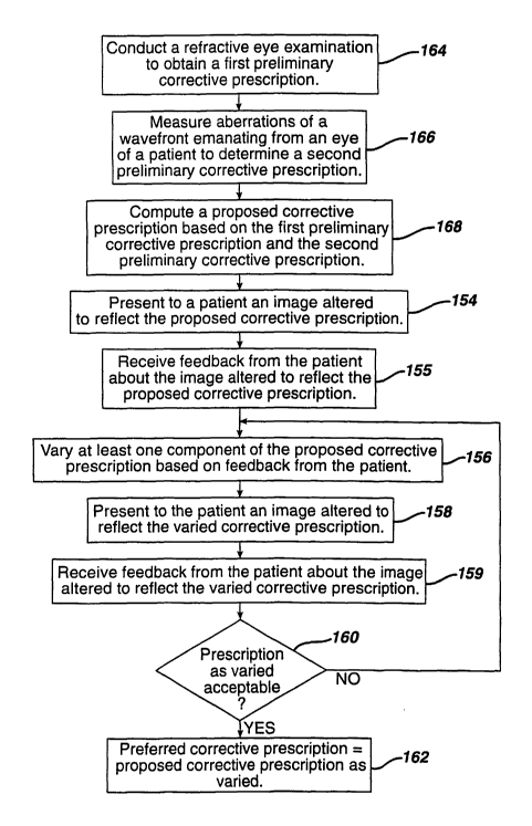
20 FIG. 4 depicts a flow chart of an alternative method _for subjectively
refining a
corrective prescription. The method is similar to the method described in FIG.
4 and similar
steps have the same reference number. Accordingly, only the steps which differ
from the
steps described in FIG. 3 will be described in detail below.
CA 02464418 2004-04-23
WO 03/034909 PCT/US02/33205
At 164, a conventional refractive eye examination is conducted using a lenown
autorefractor or retinoscope to obtain a first preliminary corrective
prescription that includes
components for correcting conventional aberrations such as defocus and
astigmatism (i.e.,
sphere, cylinder, and axis). Preferably, the conventional refractive eye
examination includes
subjectively varying components of the conventional aberrations, such as
defocus and
astigmatism, to obtain the first preliminary corrective prescription.
At 166, a WMI~ 130 of a conventional design is used to obtain a second
preliminary
corrective prescription containing components for correcting nonconventional
aberrations
such as spherical aberrations, coma, trefoil, tetrafoil, pentafoil, and other
irregularities.
At 168, a proposed corrective prescription is computed based on the first
preliminary
corrective prescription determined at 164 and the second preliminary
corrective prescription
determined at 166. In one embodiment, computing the proposed corrective
prescription
includes combining the conventional aberration components of the first
corrective
prescription with the nonconventional aberration components of the second
corrective
prescription.
Having thus described a few particular embodiments of the invention, various
alterations, modifications, and improvements will readily occur to
those.skilled in the art.
Such alterations, modifications and improvements as are made obvious by this
disclosure are
intended to be part of this description though not expressly stated herein,
and are intended to
, be within the spirit and scope of the invention. Accordingly, the foregoing
description i~ by
way of example only, and not limiting. The invention is limited only as
defined in the
following claims and equivalents thereto.
11