Note: Descriptions are shown in the official language in which they were submitted.
CA 02464734 2004-04-26
WO 03/037727 PCT/1B01/01904
RECLOSABLE PACKAGE
FIELD OF THE INVENTION
This invention generally relates to the field of material packaging and more
specifically relates to reclosable packages for confectionery items, such as
sticks of chewing
gum.
BACKGROUND OF THE INVENTION
When packaging confectionery items, particularly sticks of gum, it has been
customary to package the individual sticks of gum in a flexible package. These
flexible
packages are typically opened by pulling a narrow strip or cord that is
wrapped around one
end of the package so as to tear off the end of the package. After the package
has been
opened, the tom-off end of the package and the cord are no longer useful and
must be
discarded. As a result, once a flexible gum package has been opened, the
package cannot be
resealed or reclosed. This is because there is no lid or cap to reclose the
package.
Moreover, the package must be maintained in an upright position to keep the
remaining
sticks of gum from falling out of the package.
One solution to the above-mentioned problems is disclosed in U.S. Patent
5,638,378 which provides an adhesive at a closed end of an opened package to
retain
individual sticks of gum in the package. However, this solution has often
proven to be
unsatisfactory and inconvenient because after the package is opened, the
sticks of gum
remain exposed to the elements. As a result, the exposed sticks of gum lose
their freshness
after a short period of time.
1
CA 02464734 2006-08-28
Another solution to the above-mentioned problems is disclosed in commonly
assigned U.S. Patent 5,125,211. In the `211 patent, the package is a
reclosable package that
includes a container having a front portion, a top end portion and a back
portion. An
adhesive front label is applied to the front portion of the container and a
flexible adhesive flap
including a non-adhesive pull tab is provided for covering the label, the top
end and the back
portions of the container. The label and front portion of the container
preferably has a
contour edge formed therein to define an opening edge. During operation,
lifting the pull-tab
detaches the front portion along the contour edge and also removes the top end
to open the
package. The back of the flap remains attached to the back of the package to
form a hinged
connection. The flap is resealable to the front portion of the package to
allow the package
to be reclosed.
U.S. Patent 5,636,732 discloses a cap for a package of chewing gum. The cap
is placed over an open end of the package and has a frame which surrounds the
open end.
The frame has two windows, each of which is juxtaposed with a group of chewing
gum sticks
stored in the package. A pair of covers for the two windows is pivotally
mounted on the
frame of the cap. When it is desired to remove a stick of chewing gum from the
package, one
of the covers is opened to expose the ends of a first group of chewing gum
sticks. Once a
chewing gum stick has been removed, the cover may be closed by snapping the
lip of one of
the covers over a cooperating lip on the frame.
2
CA 02464734 2004-04-26
WO 03/037727 PCT/1B01/01904
SUMMARY OF THE INVENTION
In certain preferred embodiments of the present invention, a reclosable
package for containing one or more elongated items, such as one or more sticks
of chewing
gum, includes a container having a bottom wall and sidewalls extending from
the bottom
wall. The sidewalls preferably surround an interior region of the container
and have upper
ends that are remote from the bottom wall. The upper ends of the sidewalls
define an
opening of the container through which one or more of the elongated items may
be placed.
In one preferred embodiment, the sidewalls include a front wall, a rear wall
opposite the
front wall, and first and second sidewalls that oppose one another. The front
and rear walls
preferably include respective interior surfaces that confront one another and
the first and
second sidewalls preferably extend between the front wall and the rear wall.
In preferred
embodiments, the distance between the bottom wall and the upper end of the
rear wall is
greater than the distance between the bottom wall and the upper end of the
front wall. In
otlier words, the rear wall has a greater heiglit than the front wall. As a
result, upper ends of
the opposing sidewalls slope in a downward direction between the rear wall and
the front
wall.
The reclosable package also includes one or more dividers disposed in the
interior region of the container. The one or more dividers preferably extend
between the
opening of the container and the bottom wall. The opening of the container is
preferably
located at the upper ends of the front and rear walls. The one or more
dividers define
elongated slots adapted for receiving one or more elongated items, such as one
or more
sticks of chewing gum. In certain preferred embodiments, the one or more
dividers include
a first set of spaced ribs that are attached to and extend from the interior
surface of the front
wall toward the rear wall. The reclosable package may also include a second
set of spaced
3
CA 02464734 2004-04-26
WO 03/037727 PCT/IB01/01904
ribs that oppose the first set of spaced ribs. The second set of spaced ribs
is preferably
attached to the interior surface of the rear wall and extends from the
interior surface of the
rear wall toward the front wall. Thus, the ribs of the first and second set
preferably oppose
one another. The ribs of the first set of ribs are preferably in substantial
alignment with the
ribs of the second set of ribs, thereby fornling a series of elongated slots
defined by the
opposing ribs. The ribs are preferably integrally formed with the respective
interior surfaces
of the front and rear walls and preferably extends about 1-3 mm from the
respective interior
surfaces. In certain preferred embodiments, the first and second sets of ribs
extend from the
upper ends of the respective front and rear walls to the bottom wall. However,
in other
preferred embodiments, the ribs may only be provided on either the front wall
or the rear
wall. The ribs may also extend only part of the way between the upper ends of
the front and
rear walls and the bottom wall.
The reclosable package also preferably includes a cap attached to the
container that is closable over the opening of the container. The cap
preferably includes a
top wall, a cap front wall extending from a front edge of the top wall, a cap
rear wall
extending from a rear edge of the top wall and first and second cap sidewalls
extending
between the cap front wall and the cap rear wall. The cap is generally
attached to one of the
sidewalls of the container such as the upper end of one of the sidewalls. In
preferred
embodiments, the cap is hingedly secured to one of the upper ends of one of
the sidewalls of
the container. In preferred embodiments, the cap is hingedly secured to the
upper end of the
rear wall of the container. In highly preferred embodiments the cap and the
container are
molded together as one piece and are integrally connected together via an
integrally molded
hinge. The integrally molded hinge is preferably a flexible polymer material.
In other
preferred embodiments, the cap rear wall and the rear wall of the container
include tubular
4
CA 02464734 2004-04-26
WO 03/037727 PCT/IB01/01904
elements having axial bores extending therethrough. During assembly of the cap
to the
container, the respective tubular elements are intermesh with one another so
that the axial
bores of all of the tubular elements are in substantial alignment with one
another. An
elongated rod may then be passed through the aligned axial bores for hingedly
connecting
the cap to the container. As a result, the cap may move between a closed
position and a
fully open position by pivoting about the elongated rod.
As mentioned above, the ribs formed on the interior surfaces of the front and
rear walls provide elongated slots adapted for receiving one or more elongated
items such as
sticks of chewing gum. The ribs maintain the sticks of chewing gum in an
upright position,
even after one or more sticks of gum have been removed from the interior
region of the
container. Thus, the ribs prevent sticks of gum from falling to the side,
shifting or moving
within the interior region of the container after one or more sticks of gum
have been
removed from the package.
When the reclosable package is in the closed position, the top wall of the cap
overlies the bottom wall of the container and is substantially parallel to the
bottom wall of
the container. In this closed position, the exterior surface of the top wall
overlies the bottom
wall and is substantially parallel to the bottom wall of the container. When
the cap is in the
fully open position, the top wall of the cap does not overlie the bottom wall
of the container
and the exterior surface of the top wall faces toward the bottom wall of the
container.
The height of the cap front wall is greater than the height of the cap rear
wall.
As a result, the lower ends of the cap sidewalls (i.e., the ends of the
sidewalls remote from
the top wall of the cap) slope between the cap front wall and the cap rear
wall. The slope of
the lower ends of the cap sidewalls substantially mirrors the slope of the
upper ends of the
container sidewalls. When the cap is in the closed position, the lower end of
the cap front
5
CA 02464734 2004-04-26
WO 03/037727 PCT/IB01/01904
wall engages the upper end of the container front wall. In addition, the lower
ends of the cap
sidewalls engage the upper ends of the container sidewalls. The close
engagement of the
lower ends of the cap walls with the upper ends of the container walls
provides a seal when
the cap is in the closed position; thereby limiting the exposure of the
elongated items stored
within the container.
In certain preferred embodiments, the lower end of the cap front wall
includes a vertically extending flange that projects from the lower end of the
cap front wall
and that is engagable with a recess formed on the interior surface of the
front wall of the
container. The engagement of the vertically extending flange with the recess
holds the cap
in the closed position. Thus, the recess formed in the interior surface of the
front wall is
preferably adapted for receiving the vertically extending flange projecting
from the lower
end of the cap front wall. The cap front wall may also include a horizontally
extending
flange projecting from the exterior surface of the cap front wall. The
horizontally extending
flange is engagable for grasping the cap when the cap is moved between the
open and closed
positions.
In certain preferred embodiments, the cap is preferably hingedly connected to
the container by a hinge subassembly. The hinge subassembly preferably
includes one or
more tubular elements connected to the lower end of the cap rear wall, and one
or more
tubular elements connected to the upper end of the rear wall of the container.
Each tubular
element includes an elongated axial bore extending therethrough. During
assembly of the
cap with the container, the elongated bores of the tubular elements are placed
in substantial
alignment with one another and an elongated rod is passed through the
elongated bores of
the tubular elements for hingedly connecting the cap to the rear wall of the
container. As a
result, the cap may swing between the fully closed position. As mentioned
above, the cap
6
CA 02464734 2004-04-26
WO 03/037727 PCT/IB01/01904
may also be hingedly connected to the container by a hinge integrally molded
at one end to
the cap and at the other end to the container.
BRIEF DESCRIPTION OF THE DRAWINGS
Figure 1 shows a perspective view of a reclosable package including a
container and a cap hingedly connected to the container, in accordance with
certain preferred
embodiments of the invention.
Figures 2 shows a front view of the container of Figure 1.
Figure 3 shows a rear view of the container of Figure 2.
Figure 4 shows a left side view of the container of Figure 2.
Figure 5 shows a right side view of the container of Figure 2.
Figure 6 shows a top view of the container of Figures 2-5.
Figure 7 shows a cross-sectional view of the container of Figure 6 taken
along lines VII-VII.
Figure 8 shows a front view of the cap of Figure 1.
Figure 9 shows a rear view of the cap of Figure 8.
Figure 10 shows a right side view of the cap of Figure 8.
Figure 11 shows a right side view of the reclosable package of Figure 1
during one stage of an assembly process.
Figure 12 shows a rear view of the reclosable package shown in Figure 11.
Figure 13 shows a rear view of the reclosable package of Figure 11 during a
later stage of an assembly process.
Figure 14 shows a top view of the reclosable package shown in Figure 1.
Figure 15 shows a perspective view of the reclosable package of Figure 1 in
an open position.
Figure 16 shows a right side view of the reclosable package of Figure 15.
7
CA 02464734 2004-04-26
WO 03/037727 PCT/IB01/01904
Figure 17 shows the reclosable package of Figure 15 with elongated items
stored within the container, in accordance with certain preferred embodiments
of the present
invention.
Figure 18 shows a right side view of the reclosable package of Figure 17.
Figure 19 shows a top view of the reclosable package of Figures 17 and 18
witli the elongated items stored in the container.
Figure 20 shows a fragmentary cross-sectional view of the cap and container
taken along line XX-XX of Figure 1.
Figure 21 shows a perspective view of a reclosable package including a
container and a cap hingedly connected to the container via an integrally
molded hinge, in
accordance with further preferred embodiments of the invention.
Figure 22 shows a left side view of the package shown in Figure 21.
Figure 23 shows a right side view of the package shown in Figure 21 with the
cap in the open position.
Figure 24 shows a magnified view of the integrally molded hinge of Figure
21.
Figure 25 shows a perspective view of the package of Figure 23.
Figure 26 shows another perspective view of the package of Figure 23.
Figure 27 shows a top plan view of the package of Figure 23.
Figure 28 shows a top view of a container for a reclosable package in
accordance with further preferred embodiments of the present invention.
Figure 29 shows a top view of a container for a reclosable package in
accordance with still further preferred embodiments of the present invention.
Figure 30 shows a cross-sectional view of the container of Figure 29 taken
along line XXX-XXX of Figure 29.
DETAILED DESCRIPTION OF THE PREFERRED EMBODIMENTS
8
CA 02464734 2004-04-26
WO 03/037727 PCT/IB01/01904
Figure 1 shows a perspective view of a reclosable package 20 for storing one
or more elongated items in accordance with certain preferred embodiments of
the present
invention. The reclosable package 20 includes a container 22 having an opening
24 for
receiving the one or more elongated items (Fig. 6) and a cap 26 hingedly
connected to the
container 22. Referring to Figures 1-6, the container 22 includes a front wall
28 having an
exterior surface 30 and an interior surface 32. The container 22 also includes
a rear wall 34
having an exterior surface 36 and an interior surface 38. The container 22
also has a bottom
wall 40. The front wal128 projects from a front edge 42 of bottom wal140 and
the rear wall
34 extends from a rear edge 44 of bottom wall 40. The distance D1 between an
upper end 46
of rear wall 34 and the rear edge 44 of bottom wall 40 is greater than the
distance D2
between an upper end 48 of front wall 28 and the front edge 42 of bottom wall
40. The
container 22 also includes first sidewall 50 and second sidewall 52. The first
and second
sidewalls 50 and 52 oppose one another and extend between the front wa1128 and
rear wall
34 of container 22. Referring to Figure 6, the interior surface 32 of front
wall 28 includes a
first set of ribs 54. The first set of ribs 54 are preferably attached to the
interior surface 32
of the front wa1128 and extend from the front wall 28 toward rear wal134. The
rear wall 34
preferably includes a second set of ribs 56 attached to the interior surface
38 thereof, the
second set of ribs 56 extending toward the front wall 28. The first and second
sets of ribs 54
and 56 are preferably integrally formed to the respective front and rear walls
of the
container. In certain preferred embodiments, the ribs extend approximately one
to three
millimeters from the respective front and rear walls 28 and 34.
Referring to Figures 2-5, in certain preferred embodiments the rear wa1134 of
the container includes one or more tubular shaped elements 58A, 58B connected
to the
upper end 46 of the rear wall. Each tubular shaped element has a central bore
60A, 60B
9
CA 02464734 2004-04-26
WO 03/037727 PCT/IB01/01904
extending therethrough. The central bores 60A, 60B of tubular elements 58A,
58B are
preferably in substantial alignment with one another so that a single
elongated rod may pass
through both of the central bores 60A, 60B.
Referring to Figures 4 and 5, because the rear wall 34 has a greater height
than the front wall 28, the upper ends of the first and second sidewalls 50,
52 slope in a
downward direction between the rear wall 34 and the front wall 28. In certain
preferred
embodiments, the upper ends of the first and second sidewalls 50 and 52 slope
along a
substantially straight line extending between the upper end 46 of rear wall 34
and the upper
end 48 of front wall 28.
Figure 7 shows a cross-sectional view of the container taken along lines VII-
VII of Figure 6. As shown in Figure 7, ribs 56 extend between the upper end 46
and lower
end of the rear wall 34. The ribs 56 are preferably integrally molded to the
rear wal134 and
extend approximately 1-3 mm from the rear wall. In certain preferred
embodiments the ribs
extend from the upper end of the rear wall entirely to the lower end of the
rear wall.
However, in other preferred embodiments the ribs do not extend completely from
the upper
to the lower end of the rear wall. For example, the ribs may extend only
partially between
the upper and lower ends of the rear wall or may extend intermittently between
the upper
and lower ends of the rear wall. In still other preferred embodiments, the
ribs may be
provided on only one of the front or rear walls. For example, the ribs may be
provided only
on the interior surface of the front wall with no ribs provided on the only
surface of the rear
wall. In the alternative, the ribs may only be provided on the interior
surface of the rear wall
with no ribs provided on the front wall. Referring to Figure 6, the interior
surface 38 of the
CA 02464734 2004-04-26
WO 03/037727 PCT/IB01/01904
front wall includes a recessed portion 62, preferably at the upper end of the
front wall, for
receiving a vertically extending flange of the cap, as will be explained in
more detail below.
Referring to Figures 8-10, the cap 26 includes a top wall 64, a cap front wall
66 extending from a front edge 68 of the top wall, and a cap rear wall 70
extending from a
rear edge 72 of the top wall 64. The cap also preferably includes a first
sidewall 74 and a
second sidewall 76, the first and second sidewalls extending between the cap
front wall 66
and the cap rear wall 70. The height Ll of the cap front wall is preferably
greater than the
height L2 of the cap rear wall. In other words, the distance between a lower
end 78 of cap
front wall 66 and the top wall 64 is greater than the distance between a lower
end 80 of cap
rear wall 70 and the top wall 64. The cap front wall 66 preferably includes a
horizontally
extending flange 82 which projects from the exterior surface 84 of the cap
front wall. The
cap front wall 66 also includes a substantially vertically extending flange 86
that is attached
to an interior surface 88 of the cap front wall 66 and which projects below
the lower end 78
of the cap front wall 66. As will be explained in more detail below, the
vertically extending
flange 86 preferably engages the recess 62 (Fig. 7) formed in the interior
surface 32 of the
front wall 28 of the container when the cap is in the closed position. The
engagement of the
vertically extending flange 86 with the recess 62 provides a releasable snap
fit engagement
between the vertically extending flange 86 and the recess 62 when the cap is
in the closed
position. Referring to Figures 9 and 10, the cap also includes tubular
elements 90A, 90B
having central bores 60A', 60B' extending therethrough. The central bores are
preferably in
substantial alignment with one another.
Figures 11-13 shows one preferred method for assembling the cap 26 to the
container 22. The rear wall 34 of the container 22 and the cap rear wall 70
are abutted
11
CA 02464734 2004-04-26
WO 03/037727 PCT/IB01/01904
against one another so that the respective tubular elements 90A, 58B, 90B and
58A
intermesh with another. Referring to Figure 13, an elongated rod 92 is then
passed through
the aligned bores of the tubular elements 90A, 58B, 90B, 58A for hingedly
connecting the
cap 26 to the container 22. The rod 92 is preferably secured in place within
the aligned
bores, such as by crimping the rod. As a result, the cap is hingedly secured
to the container
and is able to swing about an axis Al extending along the longitudinal axis of
the elongated
rod 92.
Figure 14 shows a top view of the reclosable package 20 after the elongated
rod 92 has been inserted into the aligned bores of the tubular elements 90A,
58B, 90B and
58A.
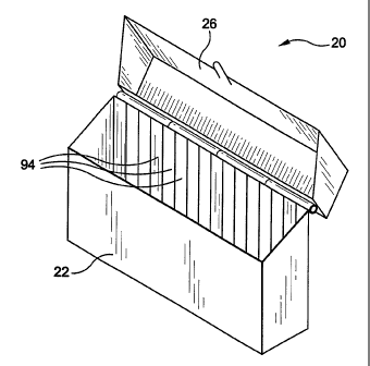
Referring to Figures 15-19, after the reclosable package has been assembled,
the cap 26 is movable between the completely open position shown in Figure 15
and the
closed position shown in Figure 1. In the open position of Figure 15, one or
more sticks of
gum may be placed into elongated slots 94. As mentioned above, the elongated
slots are
defined by the opposing ribs 54, 56. In certain preferred embodiments, the
container
includes approximately 10-20 elongated slots 94 for receiving and storing
approximately 10-
sticks of gum. However, preferred embodiments may include containers having
two or
more slots. Figures 17-19 show the reclosable package after sticks of gum 96
have been
stored in the slots 94. After the reclosable package 20 has been completed
filled with the
20 sticks of gum, the cap 26 may be closed over the opening 24 of the
container 22. The
reclosable package is preferably made of a rigid material, such as a rigid
polymer material.
As a result, the exterior surface of the package can withstand a substantial
amount of
12
CA 02464734 2004-04-26
WO 03/037727 PCT/IB01/01904
external force without those forces being transferred to the product stored
within the
package.
When it is desired to retrieve a stick of gum 96 from the package, a user may
grasp the outer surface of the container 22 and apply pressure to the
horizontally extending
flange 82 so as to witlidraw the vertically extending flange 86 from the
recess 62 formed in
the interior surface 32 of the front wall 28 of the container. The cap 26 may
then be pivoted
or swung to the open position shovcni in Figures 17 and 18. In this position,
the opening 24
at the upper end of the container 22 is completely accessible for removing one
or more
sticks of gum 96 from the elongated slots 94. After one or more sticks of gum
96 have been
removed from the package, the cap may once again be swung to the closed
position shown
in Figure 1.
Figure 20 shows a magnified fragmentary view of the cap 26 when the cap is
secured to the front wall 28 of container 22. The front wall 28 of container
22 has an
interior surface 32 including recess 62 formed adjacent an upper end of front
wall 28. The
front wall of the cap 26 includes a vertically extending flange 62 and a
horizontally
extending flange 82. When the cap 26 is swung into the closed position (Figure
1), the
vertically extending flange 86 fits into the recess 62 for securing the cap in
the closed
position. When it is desirable to open the cap, a force F1 may be exerted on
the horizontally
extending flange 82 to urge the vertically extending flange 86 away from the
recess 62.
Once the vertically extending flange is away from recess 62, the cap 26 may be
moved to the
open position shown in Figure 17.
Figures 21-27 show.a reclosable package having a cap hingedly secured to a
container in accordance with further preferred embodiments of the present
invention.
13
CA 02464734 2004-04-26
WO 03/037727 PCT/IB01/01904
Referring to Figures 21 and 22, the reclosable package 120 includes cap 126
and container
122 that are molded together in a single piece. Referring to Figures 23 and
24, the cap 126
is connected to the container 122 via hinge 192. Referring to Figure 24, the
hinge has a first
end integrally molded to cap 126 and a second end integrally molded to
container 122. The
hinge 192 is made of a flexible resilient material such as plastic so that the
cap 126 may be
repeatedly opened and closed relative to container opening 124 (Figure 23).
Figures 25-27 show the reclosable package in the open position. Referring to
Figure 25, the front wall 130 of container 128 has ribs 154 provided on
interior surface 132
thereof. The front wall ribs 154 extend toward the rear wall 134 of container
122. The
interior surface 132 of front wall 128 includes recess 162 for receiving
vertically extending
flange 186 of cap 126. The container includes a central support 197 extending
between
front wall 128 and rear wall 134. The central support 197 adds rigidity to the
container 122.
The underside of cap 126 also includes a central support 198 for adding
rigidity to the cap.
Referring to Figure 26, rear wall 134 of container 122 includes a series of
vertically
extending ribs 156 which project toward front wall 128 of container 122.
Referring to
Figure 27, the front wall ribs 154 and the rear wall ribs 156 are in
substantial alignment with
one another. The ribs define a series of slots 196 that extend between the
front wall 128 and
the rear wall 134 of the container 122. The container 122 shown in of Figure
27 has 18 slots
for receiving elongated items such as sticks of gum. However, preferred
embodiments of
the present invention may include anywhere from two slots to an infinite
number of slots for
receiving elongated items.
Figure 28 shows another alternate embodiment of the present invention
wherein ribs are provided on either the front wall or the rear wall of the
container. In the
14
CA 02464734 2004-04-26
WO 03/037727 PCT/IB01/01904
particular embodiment shown in Figure 28, the ribs 256 are provided on the
interior surface
238 of the rear wall 236 of the container 222 and no ribs are provided upon
the interior
surface 132 of the front wal1228. However, in other embodiments, ribs may be
provided on
the front wall 228 and not rear wall 236.
Figures 29 and 30 show another embodiment of the present invention
wherein ribs 356 are provided on the interior surface of the rear wall 336 and
on the upper
surface of bottom wall 340. The ribs 356 extend above the interior surface of
the front wall
336 and the interior surface of the bottom wall 340. The interior surface 332
of the front
wall 328 has no ribs.
Although the present invention has been described with reference to
particular preferred embodiments, it is to be understood that the embodiments
are merely
illustrative of the principles and application of the present invention. For
example, a wide
variety of confectionery items such as candy or mints may be stored in the
package. In
addition, the package of the present invention could be used to store
medicine, such as pills.
It is therefore understood that numerous modifications may be made to the
preferred
embodiments of the present invention without departing from the spirit and
scope of the
present invention as defined by the claims.