Note: Descriptions are shown in the official language in which they were submitted.
CA 02465016 2004-04-19
TITLE OF THE INVENTION
Packaging for Grouped Similar Items, Including Elongated Items Such as Drill
Bits and the Like.
This application is a continuation-in-part of Ser. No. 10/685,920, fiied
October 15, 2003, and presently pending.
BACKGROUND OF THE INVENTION
1. The Technical Field
[0001] The present invention is directed to packaging for grouped similar
items, including elongated items such as drill bits or the like, and further
io including packaging adapted to be hung from retail shelving.
2. The Prior Art
[0002] There are many ways to package and present in a retail
environment, elongated items, such as drill bits, jigsaw blades and the like,
including skin cards, clamshell blister packs, plastic bags, and molded or
stamped
boxes. Such elongated items may be sold in a variety of basic ways: the single
article (or at most 2-3 if small) in a package; a quantity of, e.g. 5 - 10
identical
articles in a package; an organized set of different, but related articles
(e.g., a
set of an indeterminate number of articles of varying size, grade, etc.).
[0003] Presenting a single article in a package may be advantageous, in
that in a transparent package, e.g., a bag or skin card, all or substantially
all of
the surface of the individual article may be exposed for visual inspection or
even
(in a thin bag or wrapper) tactile inspection.
[0004] However, single article packaging can be problematic in that it can
occupy more storage and shipping volume that a comparable number of like
articles packaged in bunches. Furthermore, if a customer is purchasing a large
quantity of single articles, there can be more checkout time involved.
[0005] However, plural article packaging can be problematic as well, for
elongated articles such as drill bits and the like. Such packaging may
typically
may be fabricated from plastic or paper. Plastic may be difficult to affix
identifying and marketing indicia, consumer information and the like in a
manner
1
CA 02465016 2004-04-19
which does not obscure the visibility of the products inside. Paper may permit
indicia placement but likewise typically obscures visibility of the articles
being
presented.
[0006] It would be desirable to provide a method for packaging plural
identical articles, such as elongated articles like drill bits, which has the
advantages of single article packaging, such as enabling visual inspection of
the
articles.
[0007] It would aiso be desirable to provide a method for packaging of
plural identical articles, which provides for the placement of such indicia as
may
io be desired by the manufacturer or required by law, while still permitting
visual
inspection.
[0008] These and other desirable characteristics of the present invention
will become apparent in view of the present specification, including claims,
and
drawings.
2
CA 02465016 2004-04-19
SUMMARY OF THE INVENTION
[0009] The present invention comprises in part, a package of a plurality of
like articles, having a longitudinal axis and a transverse axis. The package
comprises a first sleeve, having a length, a top end and a bottom end; and a
second sleeve, insertingly received within the first sleeve and having a
length
greater than the length of the first sleeve, a top end and a bottom end, so
that
the first sleeve overlaps at least a portion of the second sleeve in a region
of
overlap.
[0010] A first closure line extends along at least a portion of the region of
io overlap. The first closure line joins longitudinally extending inner
surfaces of the
first sleeve to adjacent longitudinally extending outer surfaces of the second
sleeve, and opposing longitudinally extending inner surfaces of the second
sleeve
to each other,
[0011] A second closure line extends transversely across at least a portion
is of the region of overlap. The second closure line joins transversely
extending
inner surfaces of the first sleeve to adjacent transversely extending outer
surfaces of the second sleeve, and opposing transversely extending inner
surfaces of the second sleeve to each other;
[0012] The first and second closure lines define first and second chambers
20 in the second sleeve, the first chamber being larger than the second
chamber,
and third and fourth chambers between the first and second sleeves, on
opposite
sides of the first chamber in the second sleeve.
[0013] A plurality of articles are disposed in the first chamber, and a single
article is disposed in the second chamber.
25 [0014] A third closure line extends transversely across the second sleeve
in
a region beyond the region of overlap, and joins transversely opposing inner
surfaces of the second sleeve, with the plurality of articles and the single
article
being disposed between the second and third closure lines, to maintain the
plurality of articles and the single article captured within the first and
second
30 chambers, respectively.
3
CA 02465016 2004-04-19
[0015] In a preferred embodiment of the invention, each of the first and
second sleeves is one of: transparent, translucent.
[0016] The package preferably further comprises at least one sheet
disposed in at least one of the third and fourth chambers disposed between the
first and second sleeves, on opposite sides of the first chamber in the second
sleeve. The at least one sheet preferably has indicia disposed thereon.
[0017] The package preferably further comprises a ffth chamber, disposed
between the third closure line and the top of the second sleeve. A
reinforcement
sheet is disposed in the third chamber between the third closure line and the
top
io of the second sleeve. A fourth closure line is disposed between the
reinforcement
sheet and the top of the second sleeve, to maintain the reinforcement sheet
captured between the third and fourth closure lines. An aperture is formed
through the second sleeve and the reinforcement sheet, for enabling the
package to be suspended by a member passing through the aperture.
[0018] Preferably, the top end of the second sleeve is longitudinally
spaced apart from the top end of the first sleeve. The bottom end of the
second
sleeve is preferably disposed proximate the bottom end of the first sleeve.
The
second sleeve preferably has a width which is less than the width of the first
sleeve.
[0019] The plurality of articles disposed in the first chamber are preferably
ali like articles, and the single article disposed in the second chamber is
the same
as one of the plurality of like articles. Preferably, the first and second
sleeves
comprise substantially flattened tubes.
[0020] The present invention also comprises, in part, a method for forming
a package, the package having a longitudinal axis and a transverse axis. The
method comprising the steps of:
forming a first sleeve, having a length, a top end and a bottom end;
forming a second sleeve, having a length greater than the length of the
first sleev.e, a top end and a bottom end;
4
CA 02465016 2004-04-19
inserting the second sleeve into the first sleeve, so that the first sleeve
overlaps at least a portion of the second sleeve in a region of overlap;
forming a first closure line, extending along at least a portion of the region
of overlap, to join longitudinally extending inner surfaces of the first
sleeve to
adjacent longitudinally extending outer surfaces of the second sleeve, and
opposing longitudinally extending inner surfaces of the second sleeve to each
other,
forming a second closure line, extending transversely across at least a
portion of the region of overlap, to join transversely extending inner
surfaces of
io the first sleeve to adjacent transversely extending outer surfaces of the
second
sleeve, and opposing transversely extending inner surfaces of the second
sleeve
to each other;
the first and second closure lines defining first and second chambers in
the second sleeve, the first chamber being larger than the second chamber, and
third and fourth chambers between the first and second sleeves, on opposite
sides of the first chamber in the second sleeve;
placing a plurality of articles in the first chamber;
placing a single article in the second chamber;
forming a third closure line, extending transversely across the second
sleeve in a region beyond the region of overlap, to join transversely opposing
inner surfaces of the second sleeve, with the plurality of articles and the
single
article being disposed between the second and third closure lines, to maintain
the plurality of articles and the single article captured within the first and
second
chambers, respectively.
[0021] The steps of forming the first and second sleeves, preferably
further comprise the step of forming each of the first and second sleeves from
one of transparent or translucent material.
[0022] The method preferably further comprises the step of:
5
........... ..... . .. .... . . . ......_......,. . .,i., ,::;. .x .M
....'NNIX ' 'k1P'RI 'Mc.' ~IeYnfiWxa>2is.-
spartnx.x.,...,=..mr.w....,.:,.,..ewa+.-..., ,...,..,xmek>c_. .zcr~Xwv
,;.ww,s:r.wz*a'+. - . . . .
CA 02465016 2004-04-19
placing at least one sheet in at least one of the third and fourth chambers
disposed between the first and second sleeves, on opposite sides of the first
chamber in the second sleeve.
[0023] The method preferably further comprises the step of placing indicia
on the at least one sheet.
[0024] The method preferably further comprises the steps of:
forming a fifth chamber, disposed between the third closure line and the
top of the second sleeve;
placing a reinforcement sheet in the third chamber between the third
io closure line and the top of the second sleeve;
forming a fourth closure line, between the reinforcement sheet and the
top of the second sleeve, to maintain the reinforcement sheet captured between
the third and fourth closure lines; and
forming an aperture through the second sleeve and the reinforcement
sheet, for enabling the package to be suspended by a member passing through
the aperture.
[0025] The method preferably further comprises the step of:
positioning the top end of the second sleeve in longitudinally spaced apart
relation to the top end of the first sleeve.
[0026] The method preferably further comprises the step of:
positioning the bottom end of the second sleeve proximate the bottom
end of the first sleeve.
[0027] The method preferably further comprises the step of:
forming the second sleeve with a width which is less than the width of the
first sleeve.
[0028] The method preferably further comprises the steps of:
selecting the plurality of articles disposed in the first chamber to be all
like
articles, and
selecting the single article disposed in the second chamber to be the same
3o as one of the plurality of like articles.
6
CA 02465016 2004-04-19
[0029] Preferably, the first and second sleeves are formed as substantially
flattened tubes.
[0030] The invention further comprises in part, a package of a plurality of
like articles, having a longitudinal axis and a transverse axis. First and
second
inner layers are provided, each having a width, extending along the transverse
axis, and a height, extending along the longitudinal axis. The frrst and
second
inner layers are joined to one another along at least three longitudinally
extending closure lines to form at least two inner chambers, for receiving
articles
to be packaged, the at least two inner chambers being bounded by the at least
io three closure lines and the first and second inner layers. The first and
second
inner layers are joined at least along respective bottom edge regions thereof.
First and second outer layers are provided, each having a width, extending
along
the transverse axis, and a height extending along the longitudinal axis. The
first
and second outer layers are disposed adjacent the first and second inner
layers,
respectively. The frrst and second outer layers are joined to their respective
adjacent frrst and second inner layers along at least two longitudinally
extending
closure lines to form at least one outer chamber. The first and second outer
layers are joined, at least indirectly, at least along respective bottom edge
regions thereof. A plurality of articles is disposed in at least one of the at
least
two inner chambers, and a number of.articles is disposed in an other one of
the
at least two inner chambers, less than the plurality of articles disposed in
the at
least one of the at least two inner chambers.
[0031] In an embodiment of the invention, the frrst and second inner
iayers are contiguously, monolithically formed together along their respective
bottom edge regions. Alternatively, the first and second inner layers may
comprise separate sheets of material that have been sealed together along
their
respective bottom edge regions.
[0032] The first and second outer layers may be contiguously,
monolithically formed together along their respective bottom edge regions.
3o Alternatively, the first and second layers may compr'ise separate sheets of
7
CA 02465016 2004-04-19
material that have been sealed together along their respective bottom edge
regions.
[0033] Each of the first and second inner layers and first and second outer
layers is one of: transparent, translucent, opaque.
[0034] The package may further comprise at least one sheet disposed in
at least one outer chamber. The at least one sheet may have indicia disposed
thereon.
[0035] The package preferably further comprises a further closure line,
extending transversely across and sealing joining top edge regions of the
first
lo and second inner layers.
[0036] The top edge regions of the first and second inner layers are
preferably longitudinally spaced apart from top edge regions of the first and
second outer layers.
[0037] The bottom edge regions of the first and second inner layers are
is preferably disposed proximate the bottom edge regions of the first and
second
outer layers.
[0038] The first and second outer layers may have widths that are less
than the widths of the first and second inner layers.
[0039] The plurality of articles disposed in the at least one of the at least
20 two inner chambers, may be all like articles, and the number of articles
disposed
in the other one of the at least two inner chambers may be the same as those
of
the plurality of like articles.
[0040] The present invention also comprises, in part, a method for forming
a package of a plurality of like articles, having a longitudinal axis and a
25 transverse axis, the method comprising the steps of:
forming first and second inner layers, each having a width, extending
along the transverse axis, and a height, extending along the longitudinal
axis,
joining the first and second inner layers to one another along at least
three longitudinally extending closure lines to form at least two inner
chambers,
8
CA 02465016 2004-04-19
for receiving articles to be packaged, the at least two inner chambers being
bounded by the at least three closure lines and the first and second inner
layers,
joining the first and second inner layers at least along respective bottom
edge regions thereof;
s forming first and second outer layers, each having a width, extending
along the transverse axis, and a height extending along the longitudinal axis,
disposing the first and second outer layers adjacent the first and second
inner layers, respectively,
joining the first and second outer layers to their respective adjacent first
io and second inner layers along at least two longitudinally extending closure
lines
to form at least one outer chamber,
joining the first and second outer layers, at least indirectly, at least along
respective bottom edge regions thereof;
placing a plurality of articles in at least one of the at least two inner
15 chambers, and
placing a number of articles in an other one of the at least two inner
chambers, less than the plurality of articles disposed in the at least one of
the at
least two inner chambers.
[0041] The method may further comprise the step of contiguously,
20 monolithically forming the first and second inner layers together along
their
respective bottom edge regions. The method may alternatively further comprise
the step of forming the first and second inner layers as separate sheets of
material that have been sealed together along their respective bottom edge
regions.
25 [0042] The method may comprise the step of contiguously, monolithically
forming the first and second outer layers together along their respective
bottom
edge regions. The method may alternatively further comprise the step of
forming
the first and second layers as separate sheets of material that have been
sealed
together along their respective bottom edge regions.
9
CA 02465016 2004-04-19
[0043] The method may further comprise the step of forming each of the
first and second inner layers and first and second outer layers as one of:
transparent, translucent, opaque.
[0044] The method may further comprise the step of placing at least one
sheet in at least one outer chamber, and may also comprise the further step of
placing indicia on the at least one sheet.
[0045] The method may further comprise the step of forming a further
closure line, extending transversely across and sealing joining top edge
regions
of the first and second inner layers.
io [0046] The method may further comprise the step of positioning the top
edge regions of the first and second inner layers in longitudinally spaced
apart
relationship from top edge regions of the flrst and second outer layers.
[0047] The method may further comprise the step of positioning the
bottom edge regions of the first and second inner layers proximate the bottom
edge regions of the first and second outer layers.
[0048] The method may further comprise the step of providing the first
and second outer layers with widths that are less than the widths of the first
and
second inner layers, and may further comprise the steps of selecting the
plurality
of articles disposed in the at least one of the at least two inner chambers,
to be
2o all like articles, and selecting the number of articles disposed in the
other one of
the at least two inner chambers to be the same as those of the plurality of
like
articles.
CA 02465016 2004-04-19
BRIEF DESCRIPTION OF THE DRAWINGS
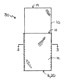
[0049] Fig. 1 is an elevation of two components of a package for similar
articles, according to a preferred embodiment of the invention.
[0050) Fig. 2 is an elevation of the two components of Fig. 1 in partially
assembled configuration.
[0051] Fig. 3 is a sectional view of the assembly of Fig. 2, taken along line
3-3 of Fig. 2.
[0052] Fig. 4 is an elevation of the assembly of Fig. 3, shown further along
the fabrication process.
io [0053] Fig. 5 is a sectional view of the assembly of Fig. 4, taken along
line
5-5 of Fig. 4.
[0054] Fig. 6 is an elevation of the assembly of Fig. 4, showing the
insertion of elongated articles into respective receiving chambers of the
package
in formation.
[0055] Fig. 7 is an elevation of the assembly of Fig. 6, showing the
insertion of indicia bearing sheets, as well as a reinforcement sheet for
enabling
the hanging display of the package.
[0056] Fig. 8 is an enlarged sectional view of the assembly of Fig. 7, taken
along line 8-8 of Fig. 7.
[0057] Fig. 9 is a perspective exploded view of two components of a
package for similar articles, according to an alternative preferred embodiment
of
the invention.
[0058] Fig. 10 is a perspective view of a package according to the
embodiment of Fig. 9, with the indicia bearing sheets and articles to be
packaged
omitted.
[0059] Fig. 11 is a side elevation of the exploded assembly of Fig. 9.
[0060] Fig. 12 is a perspective exploded view of two components of a
package for similar articles, according to an another alternative preferred
embodiment of the invention.
11
CA 02465016 2008-05-08
[0061] Fig. 13 is a perspective view of a package according to the embodiment
of Fig. 12,
with the indicia bearing sheets and articles to be packaged omitted.
[0062] Fig. 14 is a side elevation of the exploded assembly of Fig. 12.
[0063] Fig. 15 is a perspective exploded view of two components of a package
for similar
articles, according to an still another alternative preferred embodiment of
the invention.
[0064] Fig. 16 is a perspective view of a package according to the embodiment
of Fig. 15,
with the indicia bearing sheets and articles to be packaged omitted.
[0065] Fig. 17 is a side elevation of the exploded assembly of Fig. 15.
[0066] Fig. 18 is a perspective exploded view of two components of a package
for similar
articles, according to an yet another alternative preferred embodiment of the
invention.
[0067] Fig. 19 is a perspective view of a package according to the embodiment
of Fig. 18,
with the indicia bearing sheets and articles to be packaged omitted.
[0068] Fig. 20 is a side eievation of the exploded assembly of Fig. 18.
[0068a] Fig. 21 is a perspective view of an unassembled package according to
an alternative
embodiment in which the outer layer has a lesser width than the inner layer.
[0068b] FIG. 22 is a front elevation of an assembled package according to the
embodiment
of FIG. 10, with the packaged articles and Iridicia bearing sheets being
omitted for clarity of
illustration.
[0068c] FIG. 23 is a front elevation of an assembled package (in which the
articles packaged
have been omitted to facilitate illustration), according to a further
embodiment of the invention.
[0068d] FIG. 24 is a perspective view of the unassembled package according to
the
embodiment of FIG. 23, showing the different ways in which the package may be
formed.
12
CA 02465016 2004-04-19
DETAILED DESCRIPTION OF THE INVENTION
[0069] While this invention is susceptible of embodiment in many different
forms, there is shown in the drawings and will be described in detail several
specific embodiments, with the understanding that the present disclosure is to
be
considered an exemplification of the principles of the invention and is not
intended to limit the invention to the embodiments iilustrated.
[0070] A package for a plurality of similar articles according to a preferred
embodiment of the invention is formed first, as shown in Fig. 1, by forming
two
sleeves 10 and 12, each of which is preferably formed (e.g., by cutting to
desired
io length), tubular plastic material (of any suitable type - typically cut
from a roll of
flattened tube), which are preferably transparent, or alternatively
translucent,
but which will permit visual inspection of anything within the respective
sleeves.
[0071] Sleeve 10 includes open ends 14 and 16, while sleeve 12 includes
open ends 16 and 18. The material of sleeves 10 and 12 is preferably
susceptible
to welding to itself, e.g., by pressure, heat, microwave or ultrasonic
vibrations.
Sleeve 10 is inserted into sleeve 12 which preferably has a circumference
which
is slightly greater than the circumference of sleeve 10, in order to
facilitate the
insertion of sleeve 10 into sleeve 12. Alternatively, sleeve 10 may have a
circumference that is the same as or greater than that of sleeve 12, though
this
may make insertion of sleeve 10 into sleeve 12 more difficult, as well as
making
later fabrication steps slightly more difficult. In addition, sleeve 10 has a
length
which is preferably substantially greater than the length of sleeve 12.
[0072] Upon insertion, sleeves 10 and 12 form assembly 30, in which open
end 16 of sleeve 10 is preferably substantially aligned with the end 20 of
sleeve
12, although the respective ends may be unaligned if desired.
[0073] The third stage of the package formation occurs when welds 32
and 34 are provided, extending through both sleeves 10 and 12, to form
assembly 40, creating chambers 42, 44, 46, and 48. Weld 34 closes off the
bottoms 16 and 20 of sleeves 10, 12, respectively, while weld 32 creates a
vertical separation of the volume within sleeve 10. Preferably, weld 32 is off-
13
CA 02465016 2004-04-19
center, so that chamber 42 is appropriately sized for a single article 50,
while
chamber 46 is appropriately sized to receive a plurality of like articles 50.
[0074] Although chambers 44, 48 are, strictly speaking, contiguous,
because of the fact that they are, due to the typicaily flattened nature of
sleeves
10, 12, on generally opposite sides of chamber 46, it is useful to consider
them
as separate and discrete chambers. In instances in which the bulk of the
articles
being packaged causes the package to assume a less than flattened
configuration, it may be desirable to provide further welds, extending
longitudinally at the sides of the region of overlap of tubes 10, 12, so that
fully
io discrete and discontinuous chambers are created.
[0075] While welds, as described above are preferably used to create the
separations between the various chambers of the package described herein, as
being the most efficient and amenable to manufacturability, other methods of
creating the welds (or. closure lines) may be employed, such as staples or
is stitching, for example. Further, the welds or closure lines, while
preferably
extending continuously and completely across the height or width of the
respective sleeves to which they are applied, may instead be intermittent, and
may stop short of peripheral edges of the respective sleeves or at other
locations, so long as the function of restraining the articles being packaged
20 within their respective regions is accomplished.
[0076] Articles 50 are inserted into chambers 42, 46, after welds 32, 34
have been accomplished. Articles 50 are shown representationally as drill
bits,
but may be any elongated articles (e.g., center punches, etc.). Even non-
elongated articles may be accommodated, by suitably modifying the relative
25 dimensional proportions of the chambers created by the overlapped sleeves
and
the subsequently created welds.
[0077] After the articles 50 have been inserted, they are sealed in place by
weld 52, which extends across sleeve 10, but does not contact the top of
sleeve
12, thus leaving the tops of chambers 44, 48 stiil open, and as well leaves
the
30 top of sleeve 10, above weld 52, likewise open for insertion of further
items,
14
CA 02465016 2004-04-19
Sheets 54, 56 may be provided with various indicia (product name, product
information, UPC bar code(s), etc.) as desired or required by law. Sheets 54,
56
may be fabricated from any suitable material capable of bearing indicia, and
once prepared and suitably printed, are inserted into chambers 44, 48,
respectively.
[0078] As the side shown in Fig. 7 is preferably the nominal "front" of the
package, it is intended to be placed on a sheif, so that sheet 56 faces front.
Sheet 56 preferably is "shorter" than the articles 50 (e.g., drill bits), so
that the
tops of the articles will be visible, while sheet 54 may or may not be of
equal or
io greater length than articles 50. Sheet 54 will be rotated 180 degrees (as
indicated by the arrow), so that its indicia face to the rear (although either
sheet
may be provided with indicia on both sides, as necessary or desired).
[0079] Once sheets 54, 56 have been inserted, a further weld may be
placed across the tops of chambers 44, 48. However, in usual practice this may
not be necessary, as sheets 54, 56 will be sized so that the fit of each
within its
respective chamber 44, 48 will be sufficiently snug enough that sheets 54, 56
will
not fall out, subsequent to fabrication, to prevent sheets 54, 56 from being
dislodged during shipment, through placement on retail shelving, up to
purchase
by a consumer.
[0080] The placement of sheets 54, 56 in the chambers 44, 48, rather
than immediately adjacent to articles 50 is advantageous, in that articles 50,
which may be, e.g., drill bits or other tool parts, may be coated with oil or
other
materials, for example, to prevent rusting or other damage to the articles,
pending purchase by the consumer. This coating may be harmful or detrimental
to the indicia that is printed on the sheets, in that it may blur the printing
or
adversely affect the material of the sheets themselves. By placing the sheets
54,
56 within chambers 44, 48, they are isolated from the articles, and cannot be
affected by them or any coating or the like.
[0081] After placement of the sheets, and possible, though not required,
welding of the tops of chambers 44, 48, the package is then prepared for
CA 02465016 2004-04-19
hanging. Depending upon the strength of the material, the top of sleeve 10 may
be simply closed by a further weld 58. Alternatively, a further sheet 60
(which
may or may not also have indicia placed on it) is inserted above weld 52,
prior to
placement of weld 58, to provide reinforcement strength for enabling the
package to be hung on a peg, rod or hook. Once in place, a hole 62 is formed
through the layers of sleeve 10 and sheet 60, in any suitable shape that is
appropriate for enabling the completed package 70 to be hung via a peg or
hook, from a retail display shelf. Depending upon the characteristics of the
particular materials from which sleeve 10 and sheet 60 are fabricated, the act
of
io die cutting hole 62 may serve to press onto or microweld the layers of
sleeve 10
to the sides of sheet 60, proximate to hole 62, so that the edges of sleeve 10
that define hole 62 are not loose, but more or less affixed to sheet 60.
[0082] A further vertical weld 64 may be provided if desired, to prevent
sheet 60 from migrating laterally, and to obviate the need for sheet 60 to
extend
across the entire width of the top of sleeve 10. Alternatively, sheet 60 may
be
made to have a width approximately equal to the width of sleeve 10.
[0083] Package 70 has the advantage of providing for the packaging of a
plurality of like articles in a compact and economic manner, while at the same
time displaying a single representative one of the articles in a complete
manner
for unencumbered visual inspection. Furthermore, package 70 enables indicia
such as product information to be provided in a manner which is not interfered
with by the articles being packaged.
[0084] While in preferred embodiments of the invention, in the package,
the articles packaged are all identical or substantially so, in alternative
embodiments of the invention, one or more of the articles may be non-
identical.
[0085] Figs. 9 - 11 illustrate components and an assembly thereof, for a
package according to an alternative embodiment of the invention. In this
embodiment the package may be formed from two sheets 102, 104 of plastic (or
similar) transparent material. The articles being packaged, and the indicia
3o bearing sheets of the prior embodiments have been omitted from the
16
CA 02465016 2004-04-19
illustrations, but are understood to be present in finished packages
fabricated in
accordance with the description hereinafter.
[0086] Sheets 102, 104 preferably have the same width, but sheet 102 is
longer than sheet 104. Sheet 102 is folded upon itself, to form legs 106, 108,
while sheet 104 is folded about sheet 102, to form legs 110, 112. Thereafter,
seams (or closure lines) 114, 116, 118 and 120 are formed by heat, ultrasonic
or RF (radio frequency) waves, through all layers of sheets 102, 104, to form
three long inner chambers across, between legs 106 and 108; three outer short
chambers across between legs 106 and 110; and three short outer chambers
io across between legs 108 and 112. For example, edges 122, 124 and 126 define
the mouths of the three short chambers on the upper side of package 100, as
seen in Fig. 9.
[0087] In the embodiment of Figs. 9 - 11, the outer sheet 104 is folded
about inner sheet 102 in such a manner that the free edges of legs 110, 112 of
sheet 104 are the same distance from the fold 111. In alternative embodiments,
sheet 104 may be shifted so that the free edges of legs 110, 112 are at
different
distances from the fold. Furthermore, while in the embodiment of Figs. 9 - 11,
three sets of three chambers extending across the width of package 100 are
shown, it is to be understood that one of the seams (e.g., 118) may be
omitted,
to provide for two chambers extending across, or that more seams may be
provided, without departing from the scope of the invention.
[0088] One or more articles, such as drills 122 (Fig. 10) may be inserted
into one or more of the inner chambers between legs 106 and 108, preferably in
the manner described with respect to the previously described embodiments,
wherein a plurality of like articles are placed in one or two of the long
chambers,
while a one or two exemplary articles are placed by themselves in a separate
one
of the chambers. For example, a package constructed according to Figs. 9 - 11
may have in one long chamber a group of several examples of a particular style
or model of article; in another long chamber, a group of several examples of
3o another particular style or model of article, and in a third long chamber,
one
17
CA 02465016 2004-04-19
example of each. Thereafter, a further seam (not shown) may be placed across
the entire width (or some lesser part thereof) of the aligned free edges of
legs
106, 108, to capture the articles received in the chambers. Indicia bearing
cards
may be placed in one or more of the short chambers formed between legs 106,
110, and 108, 112, respectively, while preferably not in the short chambers
adjacent to the long chamber containing the single (or small number) of
examples of the groups of articles enclosed in the other long chambers. In
alternative embodiments, sheet 104 (or the corresponding separate outer layer
sheets of the subsequently described embodiments) may have a width that is
io less than the width of sheet 102 (or the corresponding separate inner layer
sheets of the subsequently described embodiments) to define a fewer number of
outer chambers, than of inner chambers.
[0089] In the embodiments shown in Figs. 9 - 20, the inner and outer
chambers all have approximately the same width, due to the substantially
equidistant spacing between the longitudinal seams. However, it is understood
that the spacing between the seams may be varied so that, for example, one
inner chamber is substantially wider or narrower than the other(s) of the
inner
chambers, again for purposes of providing one example of an article being
packaged set off from a group of others of the same article, for permitting
thorough inspection of the individually set-off article.
[0090] Figs. 12 - 14 illustrate another alternative embodiment of the
invention, wherein a package similar to that of Figs. 9 - 11 is formed from
three
sheets of plastic material. Package 200 is formed from sheets 202, 204 and
folded sheet 206. Sheets 202, 204 are joined together along their respective
bottom edges at seam 208, as shown in Figs. 12 and 14, and then sheet 206 is
folded about the bottom seam of sheets 202, 204, to form legs 210, 212.
Vertical
seams 214, 216, 218 and 220 are formed, in the same manner as in the
embodiment of Figs. 9 - 11. Again, there are three long chambers formed, by
seams 214, 216, 218 and 220, between sheets 202 and 204, and three short
sheets across, between sheet 202 and leg 210, and between sheet 204 and leg
18
_, --- ------- ~
CA 02465016 2004-04-19
212. Placement of the articles to be packaged, and the indicia bearing cards,
may be accomplished in the same varieties of ways, as described with respect
to
the previously-described embodiments. Again, a greater or lesser number of
"vertical" seams may be used, to make greater or fewer numbers of chambers
extending across the width of the package.
[0091] A further alternative embodiment is shown in Figs. 15 - 17, wherein
package 300 is formed from folded sheet 302, and sheets 304, 306. Sheet 302 is
folded at fold 308, to form legs 310, 312. Then sheets 304, 306 are aligned
over
legs 310, 312 as shown. Sheets 304, 306 are joined together along fold 308, to
io form seam 314. Vertical seams 316, 318, 320 and 322 are then created, to
form
long chambers between legs 310, 312, and to form short chambers between leg
310 and sheet 304, and between leg 312 and sheet 306. Placement of the
articles to be packaged, and the indicia bearing cards, may be accomplished in
the same varieties of ways, as described with respect to the previously-
described
embodiments. Again, a greater or lesser number of "vertical" seams may be
used, to make greater or fewer numbers of chambers extending across the width
of the package.
[0092] A still further alternative embodiment of the invention is illustrated
in Figs. 18 - 20. Four sheets 402, 404, 406 and 408 are provided, which are
2o arranged in overlying fashion as shown in Figs. 18 and 20. The sheets are
then
attached to one another by one of the methods previously described, to form
seams 410, 412, 414, 416 and 418, again to form long chambers between sheets
404 and 406, and short chambers between sheets 402, 404 and between sheets
406, 408. Placement of the articles to be packaged, and the indicia bearing
cards, may be accomplished in the same varieties of ways, as described with
respect to the previously-described embodiments. Again, a greater or lesser
number of "vertical" seams may be used, to make greater or fewer numbers of
chambers extending across the width of the package.
[0093] In the embodiments of Figs. 9 - 20, the sheets that make up the
inner and outer layers of the packages are preferably fabricated from a
suitable,
19
CA 02465016 2004-04-19
sealable plastic material, that may be heat, ultrasonic or RF sealed, and
which
may be transparent, translucent or, at least in places opaque. The sheets may
be
fabricated from material upon which indicia may be printed.
[0094] The foregoing description and drawings merely explain and
illustrate the invention, and the invention is not limited thereto, except as
those
skilled in the art who have the present disclosure before them will be able to
make modifications and variations therein without departing from the scope of
the invention.