Note: Descriptions are shown in the official language in which they were submitted.
CA 02465459 2004-04-27
-1-
Title: CABINET DOOR SUPPORT MECHANISM
Field of the Invention
[0001] This invention relates generally to cabinets primarily, but not
exclusively, so-called overhead cabinets intended for use in an office
environment. It is, however, to be understood that the invention may be
applied to cabinets used in other environments, for example, kitchens or other
residential locations.
Background of the Invention
[0002] An overhead cabinet as used in an office typically is supported
from a partition or other wall structure at an appropriate height above a work
surface. An overhead cabinet may also be incorporated as part of a piece of
office furniture, for example, a free-standing wall unit.
[0003] Traditionally, the cabinet is provided with doors that are hinged
to the cabinet about a vertical inner edge of the door so that the door swings
outwardly to give access to the interior of the cabinet. While this type of
door
is perfectly functional and acceptable in many situations, it is desirable to
provide a door that opens upwardly so as to avoid obstructing space laterally
of the door. Mechanisms are available for supporting upwardly opening
doors. However, in general, these mechanisms simply comprise
parallelogram linkages at opposite sides of the door that constrain the door
to
move up and down while remaining upright. In other words, the door is in a
vertical plane in its normal closed position and remains parallel to that
plane
as it moves up to the open position. Typically, springs are used to hold the
door open.
[0004] Again, this type of door support mechanism is satisfactory from
a functional standpoint. However, it is necessary to provide for space above
the cabinet to accommodate the door in its open position. Also, the door may
look somewhat unsightly in the open position, for example, if it protrudes
above an office partition.
CA 02465459 2004-04-27
-2-
Summary of the Invention
[0005] An object of the present invention is to provide an improved door
support mechanism which addresses some of these issues.
[0006] According to the invention there is provided a door support
mechanism for a cabinet having an open front, respective end walls at
opposite sides of the front and a door for closing the open front. The
mechanism supports the door for movement between a closed position in
which the door adopts a generally upright orientation and extends across the
open front of the cabinet, and an elevated open position in which the door
adopts an at least partly horizontal orientation above the cabinet. The
mechanism includes, on each end wall of the cabinet, a pair of unequal length
links each having a first end pivotally coupled to the relevant end wall of
the
cabinet at a first pivot point and a second end pivotally coupled to the door
at
a second pivot point. The unequal length links are configured and arranged to
support the door for movement between said open and closed positions. On
at least one of the cabinet end walls is a device comprising a cylinder and a
ram which biased outwardly of the cylinder. The device is pivotally coupled at
one end to the relevant cabinet end wall and at the other to one link of the
relevant pair of links at a third pivot point. The said one link comprises a
bell
crank pivoted about said first pivot point with said second and third pivot
points defining respective arms of the bell crank. The cylinder and ram device
acts on the bell crank link in a direction to assist movement of the door
upwardly from the closed position and is itself acted upon by said link as the
door returns towards its closed position, cushioning closing movement of the
door.
[0007] In summary, the invention provides a cabinet door that moves
up and over the cabinet when the door is opened. The user lifts the door from
the closed position and the cylinder and ram device provides an assist force
in
effect reducing the effort that otherwise would be required to open the door.
Conversely, when the door is to be closed, the user initiates movement of the
CA 02465459 2004-04-27
-3-
door away from the open position and the closing movement is cushioned by
the cylinder and ram device, providing a "soft close".
[0008] The two pairs of linkages (on the respective end walls of the
cabinet) preferably are mechanically coupled together. This allows a cylinder
and ram device to be used at one end of the cabinet only at least for short
(narrow) cabinets. Preferably, cylinder and ram devices are provided at both
ends of the cabinet in the interest of balanced opening and closing of the
door.
[0009] In one embodiment, each pair of links includes a longer link that
is pivoted at its first end generally in the center of the relevant end wall
and at
its second end to the door, adjacent its lower edge. The second, shorter link
comprises the bell crank of the mechanism and is pivotally coupled at its
first
end to the end wall of the cabinet adjacent the top edge of that wall, and at
its
second end to an upper region of the door. The cylinder and ram device is
coupled to this upper link and the two upper links are coupled together by a
common shaft that runs horizontally from end-to-end of the cabinet.
Brief Description of the Drawings
[0010] In order that the invention may be more clearly understood,
reference will now be made to the accompanying drawings which illustrate a
particular preferred embodiment of the invention, and in which:
[0011] Fig. 1 is a three-quarter perspective view from the front and one
end of a cabinet provided with a door support mechanism in accordance with
the invention, the door being shown in a partially open position;
[0012] Figs. 2 to 5 are end elevational views from the left in Fig. 1
showing the sequence of movement of the door from the closed position (Fig.
2) to the open position (Fig. 5); and,
[0013] Fig. 6 is a detail elevational view showing the upper link of the
mechanism in full lines in the fully open position of the door and in ghost
outline in a partially closed position.
CA 02465459 2004-04-27
-4-
Description Preferred Embodiment
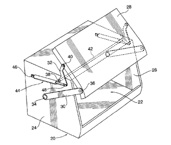
[0014] Referring first to Fig. 1, a typical overhead cabinet is generally
indicated by reference numeral 20 and has an open front 22 and respective
end walls 24, 26 at opposite sides of the open front. A door for closing the
open front is shown at 28 in a partially open (or partially closed) position.
The
cabinet is provided with a mechanism which supports the door 28 for
movement between a closed position (Fig. 2) in which the door adopts a
generally upright orientation and extends across the open front 22 of the
cabinet, and an elevated open position (Fig. 5) in which the door adopts an at
least partly horizontal orientation above the cabinet.
[0015] Figs. 3 and 4 show intermediate positions that the door adopts
in sequence as it moves from the closed position of Fig. 2 to the open
position
of Fig. 5. Of course, the reverse sequence applies when the door is moved to
the closed position. In moving from the closed position of Fig. 2, the door
travels along a defined path in which it initially moves away from the front
of
the cabinet (Fig. 3) and then upwardly and angles rearwardly (Fig. 4) before
arriving at the elevated open position shown in Fig. 5.
[0016] The mechanism includes a pair of unequal length links on each
end wall of the cabinet, and a cylinder and ram device (preferably a gas
cylinder) that acts on one of the links in each pair. The respective pairs of
links are essentially a mirror image of one another and therefore only one
pair
will be described, namely the pair that is carried by the left-hand end wall
24
as seen in Fig. 1 and in Figs. 2 to 5.
[0017] The two links are denoted 30 and 32 and each link has a first
end pivotally coupled to the cabinet end wall at a first pivot point and a
second
end pivotally coupled to the door at a second pivot point. The first pivot
point
for link 30 is denoted 34 and the second pivot point 36, while the two
corresponding pivot points for link 32 are denoted 38 and 40 respectively.
[0018] The longer of the two links (link 30) is pivoted to the end wall 24
generally in a center region of the end wall, while the second pivot point 36
for
CA 02465459 2004-04-27
-5-
that link is located adjacent the bottom edge of door 28. In fact, the link is
coupled to an end edge of the door.
[0019] The first pivot point 38 of the shorter link 32 is located adjacent a
top edge of the cabinet end wall and a second pivot point 40 of that link is
located in an upper region of the end edge of the door 28. The two shorter
links 32 at respectively opposite ends of the cabinet are coupled together by
a
common pivot shaft 42 (see Fig. 1) which ensures that the two links move in
unison.
[0020] Associated with the upper link 32 is a gas cylinder and ram
device 44 which is pivotally coupled at the cylinder end to the end wall 24 at
pivot point 46, and pivotally coupled at its ram end to the upper link 32 at a
pivot point 48. The link is configured to form a bell crank that pivots about
first
pivot point 38, with the door 28 coupled to one arm of the bell crank at 40
and
the cylinder and ram device 44 coupled to the other end of the bell crank at
48.
[0021] In the door-closed position of Fig. 2, device 44 is exerting a
turning moment on link 32 about pivot point 38. However, device 44 is
calibrated so that the force that is exerted on link 32 is not sufficient in
itself to
raise the door. In other words, the door remains closed. However, when a
user begins to lift the door, device 44 assists that movement by virtue of the
moment that it exerts about pivot 38. Once movement of the door has begun,
the movement will continue until the door reaches the fully open position of
Fig. 5.
[0022] Fig. 6 shows the upper link 32 in full lines in that position. The
line denoted A-A extends between the pivot point 46 between device 44 to
end wall 24 and the first pivot point 38 for the bell crank link 32. This line
represents a "null" or over-center position in that, when device 44 is
disposed
on line A-A, it cannot exert any turning moment on link 32. In the full line
position of link 32 (door fully open), pivot point 48 is slightly above line A-
A
(distance D) so the linkage has gone "over-center". The door will then remain
in this fully open position until physically moved back towards the closed
CA 02465459 2011-09-16
-6-
position. Distance D should be a relatively small positive value so that,
while
the linkage does go over-center, movement of link 32 does not begin to
significantly compress device 44 (since that would inhibit full opening of the
door).
[0023] To close the door, the user pulls downwardly on the door.
Device 44 passes over-center in the opposite direction (i.e. crosses line A-A)
and the link 32 then begins to exert a compressive force on the cylinder and
ram device 44 represented by the weight of the door and any downward force
applied by the user. Device 44 cushions of the closing movement of the door,
providing a "soft close" effect.
[0024] In summary, the invention provides a so-called "up-assist/soft
close" action for the door.
[0025] It will of course be appreciated that the preceding description
relates to a particular preferred embodiment of the invention only and that
modifications are possible. Some of those modifications are indicated herein,
and other will be apparent to a person skilled in the art. Of course, the
particular shapes of the links can vary within the functional constraints of
the
invention. The cylinder and ram device 44 is preferably a gas-filled device,
but mechanical spring devices may be used. Device 44 could act on the
lower link 30 rather than the upper link 32. The particular design of the
cabinet may of course vary. For example, the cabinet could have a flat
vertical or inclined door, It should also be noted that the mechanism provided
by the invention is applicable to cabinets of varying lengths. In fact, in
embodiments in which there is a connecting shaft as shaft 42 extending from
end-to-end of the cabinet, it is possible to apply the invention to cabinets
as
long as 60" or more. Conversely, shorter cabinets having a connecting shaft
may require a cylinder and ram device (as device 44) at one end only.
[0026] In the illustrated embodiment, the pairs of links are shown
mounted on the outer faces of the end walls of the cabinet and coupled to end
edges of the door itself. The cabinet end walls may be provided with
CA 02465459 2004-04-27
-7-
outwardly spaced trim panels to conceal the links and cylinder and ram
device. Alternatively, it would be possible to mount the links on the inner
faces of the end walls of the cabinet but it would then be necessary to
provide
appropriate slots or gaps to accommodate movement of the links. Also, the
links could be pivotally coupled to the inner face of the door rather than to
end
edges of the door.