Note: Descriptions are shown in the official language in which they were submitted.
CA 02465552 2004-05-18
Patent
Atty. Docket No. ALPH.P027W0
METHOD AND APPARATUS FOR REMOVING NOISE FROM
ELECTRONIC SIGNALS
RELATED APPLICATIONS
This patent application is a continuation in part of U.S. Patent Application
S Serial No. 09/905,361, filed July 12, 2001, which is hereby incorporated by
reference
This patent application also claims priority from U.S. Provisional Patent
Application
Serial No. 60/332,202, filed November 21, 2001.
FIELD OF THE INVENTION
The invention is in the field of mathematical methods and electronic systems
for
removing or suppressing undesired acoustical noise from acoustic transmissions
or
recordings.
BACKGROUND
In a typical acoustic application, speech from a human user is recorded or
stored
and transmitted to a receiver in a different location. In the environment of
the user,
there may exist one or more noise sources that pollute the signal of interest
(the user's
speech) with unwanted acoustic noise. This makes it difficult or impossible
for the
receiver, whether human or machine, to understand the user's speech This is
especially problematic now with the proliferation of portable communication
devices
like cellular telephones and personal digital assistants. There are existing
methods for
suppressing these noise additions, but they have significant disadvantages For
example, existing methods are slow because of the computing time required.
Existing
methods may also require cumbersome hardware, unacceptably distort the signal
of
interest, or have such poor performance that they are not useful. Many of
these existing
methods are described in textbooks such as "Advanced Digital Signal Processing
and
Noise Reduction" by Vaseghi, ISBN 0-471-62692-9.
BRIEF DESCRIPTION OF THE FIGURES
Atty. Docket No. ALPH.P027W0 -1-
CA 02465552 2004-05-18
Patent
Atty. Docket No. ALPH.P027W0
Figure 1 is a block diagram of a denoising system, under an embodiment.
Figure 2 is a block diagram illustrating a noise removal algorithm, under an
embodiment assuming a single noise source and a direct path to the
microphones.
Figure 3 is a block diagram illustrating a front end of a noise removal
algorithm
of an embodiment generalized to n distinct noise sources (these noise sources
may be
reflections or echoes of one another).
Figure 4 is a block diagram illustrating a front end of a noise removal
algorithm
of an embodiment in a general case where there are n distinct noise sources
and signal
reflections.
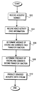
Figure 5 is a flow diagram of a denoising method, under an embodiment.
Figure 6 shows results of a noise suppression algorithm of an embodiment for
an American English female speaker in the presence of airport terminal noise
that
includes many other human speakers and public announcements.
Figure 7 is a block diagram of a physical configuration for denoising using
1 S unidirectional and omnidirectional microphones, under the embodiments of
Figures 2,
3, and 4.
Figure 8 is a denoising microphone configuration including two
omnidirectional microphones, under an embodiment.
Figure 9 is a plot of the C required versus distance, under the embodiment of
Figure 8.
Figure 10 is a block diagram of a front end of a noise removal algorithm under
an embodiment in which the two microphones have different response
characteristics.
Figure 11A is a plot of the difference in frequency response (percent) between
the microphones (at a distance of 4 centimeters) before compensation.
Figure 11B is a plot of the difference in frequency response (percent) between
the microphones (at a distance of 4 centimeters) after DFT compensation, under
an
embodiment.
Figure 11C is a plot of the difference in frequency response (percent) between
the microphones (at a distance of 4 centimeters) after time-domain filter
compensation,
under an alternate embodiment.
Atty. Docket No. ALPH.P027W0 -2-
CA 02465552 2004-05-18
Patent
Ariy. Docket No. ALPH.P027W0
DETAILED DESCRIPTION
The following description provides specific details for a thorough
understanding
of, and enabling description for, embodiments of the invention. However, one
skilled
in the art will understand that the invention may be practiced without these
details In
other instances, well-known structures and functions have not been shown or
described
in detail to avoid unnecessarily obscuring the description of the embodiments
of the
invention.
Unless described otherwise below, the construction and operation of the
various
blocks shown in the figures are of conventional design. As a result, such
blocks need
not be described in further detail herein, because they will be understood by
those
skilled in the relevant art. Such further detail is omitted for brevity and so
as not to
obscure the detailed description of the invention. Any modifications necessary
to the
blocks in the Figures (or other embodiments) can be readily made by one
skilled in the
relevant art based on the detailed description provided herein.
Figure 1 is a block diagram of a denoising system of an embodiment that uses
knowledge of when speech is occurring derived from physiological information
on
voicing activity. The system includes microphones 10 and sensors 20 that
provide
signals to at least one processor 30. The processor includes a denoising
subsystem or
algorithm 40.
Figure 2 is a block diagram illustrating a noise removal algorithm of an
embodiment, showing system components used. A single noise source and a direct
path to the microphones are assumed. Figure Z includes a graphic description
of the
process of an embodiment, with a single signal source 100 and a single noise
source
101. This algorithm uses two microphones: a "signal" microphone 1 ("MIC 1 ")
and a
"noise" microphone 2 ("MIC 2"), but is not so limited. MIC 1 is assumed to
capture
mostly signal with some noise, while MIC 2 captures mostly noise with some
signal.
The data from the signal source 100 to MIC 1 is denoted by s(n), where s(n) is
a
discrete sample of the analog signal from the source 100. The data from the
signal
source 100 to MIC 2 is denoted by sZ(n). The data from the noise source 101 to
MIC 2
is denoted by n(n). The data from the noise source 101 to MIC 1 is denoted by
n2(n).
Atty. Docket No. ALPH.P027W0 -3-
CA 02465552 2004-05-18
Patent ~ '
Atty. Docket No. ALPH.P027W0
Similarly, the data from MIC 1 to noise removal element 105 is denoted by
rr~(n), and
the data from MIC 2 to noise removal element 105 is denoted by m2(n).
'The noise removal element also receives a signal from a voice
activitydetection
("VAD") element 104. The VAD 104 detects uses physiological information b
determine when a speaker is speaking. In various embodiments, the VAD includes
a
radio frequency device, an electroglottograph, an ultrasound device, an
acoustic throat
microphone, and/or an airflow detector.
The transfer functions from the signal source 100 to MIC 1 and from the noise
source 101 to MIC 2 are assumed to be unity. 'Ihe transfer function from the
signal
source 100 to MIC 2 is denoted by HZ(z), andthe transfer function from the
noise
source 101 to MIC 1 is denoted by H,(z). The assumption of unity transfer
functions
does not inhibit the generality of this algorithm, as the actual relations
between the
signal, noise, and microphones are simply ratios and the ratios are redefined
in this
manner for simplicity.
In conventional noise removal systems, the information from MIC 2 is used to
attempt to remove noise from MIC 1. However, an unspoken assumption is that
the
VAD element 104 is never perfect, and thus the denoising must be performed
cautiously, so as not to remove too much of the signal along with the noise.
However,
if the VAD 104 is assumed to be perfect such that it is equal to zero when
there is no
speech being produced by the user, and equal to one when speech is produced, a
substantial improvement in the noise removal can be made.
In analyzing the single noise source 101 and the direct path to the
microphones,
with reference to Figure 2, the total acoustic information coming into MIC I
is denoted
by m,(n). The total acoustic information coming into MIC 2 is similarly
labeled mz(n~
In the z (digital frequency) domain, these are represented as M~(z) and MZ(z).
Then
M,(z) =S(z)+Ni (z)
Mz (z)= N(z)+ SZ (z)
with
NZ (z) = N(z)H, (z)
S2 (z)=S(z)H? (z)
Atty. Docket No. ALPH.P027W0 -4-
CA 02465552 2004-05-18
Patent
Atty. Docket No. ALPH.P027W0
SO that
M, (z) = S(z) + N(z)H, (z)
MZ (z) = N(z) + S(z)Hz (z) Eq. 1
This is the general case for all two microphone systems In a practical system
S there is always going to be some leakage of noise into MIC 1, and some
leakage of
signal into MIC 2. Equation 1 has four unknowns and only two known
relationships
and therefore cannot be solved explicitly.
However, there is another way to solve for some of the unknowns in Equation 1.
The analysis starts with an examination of the case where the signal is not
being
generated, that is, where a signal from the VAD element 104 equals zero and
speech is
not being produced. In this case, s(n) = S(z) = 0, and Equation 1 reduces to
M," (z)=N(z)H, (z)
M2" (z)= N(z)
where the n subscript on the M variables indicate that only noise is being
received.
This leads to
Mm (z)=Mz" (z)H, (z)
HI(z)=Mm (z) Eq, 2
Mzn (Z)
H,(z) can be calculated using any of the available system identification
algorithms and the microphone outputs when the system is certain that only
noise is
being received. The calculation can be done adaptively, so that the system can
react to
changes in the noise.
A solution is now available for one of the unknowns in Equation 1. Another
unknown, HZ(z), can be determined by using the instances where the VAD equals
one
and speech is being produced. When this is occurring, but the recent (perhaps
less than
1 second) history of the microphones indicate low levels of noise, it can be
assumed
that n(s) = N(z) ~ 0. Then Equation 1 reduces to
M,S (z) = S(z)
MZJ (z)=S(z)Hz (z)
Atty. Docket No. ALPH.P027W0 -5-
CA 02465552 2004-05-18
Patent
Atty. Docket No. ALPH.P027W0
which in turn leads to
MzJ (z)=M~J (z)Hz (z)
__Mzf(z)
Hz (z) Mn (z)
which is the inverse of the H,(z) calculation. However, it is noted that
different inputs
S are being used - now only the signal is occurnng whereas before only the
noise was
occurnng. While calculating HZ(z), the values calculated for H,(z) are held
constant
and vice versa. Thus, it is assumed that while one ofH,(z) and HZ(z) are being
calculated, the one not being calculated does not change substantially.
After calculating H,(z) and HZ(z), they are used to remove the noise from the
signal. If Equation 1 is rewritten as
S(z)=M, (z)- N(z)H, (z)
N(z)=Mz (z)-S(z)H1 (z)
S(z) =M, (z) - (M, (z)- S(z)Hz (z)JH, (z)'
S(z)~1-H2 (z)H, (z)J =M, (z)-MZ (z)H, (z)
then N(z) may be substituted as shown to solve for S(z) as:
S(z)= M~ (z)-Mz (z)H~ (z) , Eq. 3
1- HZ (z)H, (z)
If the transfer functions H,(z) and HZ(z) can be described with sufficient
accuracy, then the noise can be completely removed and the original signal
recovered.
This remains true without respect to the amplitude or spectral characteristics
of the
noise. The only assumptions made are a perfect VAD, sufficiently accurate
H,(z) and
HZ(z), and that when one of H,(z) and HZ(z) are being calculated the other
does not
change substantially. In practice these assumptions have proven reasonable.
The noise removal algorithm described herein is easily generalized to include
any number of noise sources. Figure 3 is a block diagram of a front end of a
noise
removal algorithm of an embodiment, generalized to n distinct noise sources
These
distinct noise sources may be reflections or echoes of one another, but are
not so
limited. There are several noise sources shown, each with a transfer function,
or path,
to each microphone. The previously named path HZ has been relabeled as Hp, so
that
Atty. Docket No. ALPH.P027W0 -6-
CA 02465552 2004-05-18
Patent
Atty. Docket No. ALPH.P027W0
labeling noise source 2's path to MIC 1 is more convenient. The outputs of
each
microphone, when transformed to the z domain, are:
M, (z)= S(z) + N, (z)H, (z)+ NZ (z)Hz (z)+ . . . N" (z)H" (z)
MZ (z)= S(z)Ho (z) + N, (z)G, (z) + NZ (z)Gz (z) +. . . N" (z)G" (z) Eq. 4
When there is no signal (VAD = 0), then (suppressing the z's for clarity)
M," =N,H, +NIHZ +...N"H"
Mz" =N,G, +NzGz +...N"G" Eq. S
A new transfer function can now be defined, analogous to H,(z) above:
H -M," _-N,H,+NzH1+...N"H" E . 6
MZ" N,G, +N1G1 +...N"G" q
Thus H , depends only on the noise sources and their respective transfer
functions and
can be calculated any time there is no signal being transmitted. Once again,
the n
subscripts on the microphone inputs denote only that noise is being detected,
while an s
subscript denotes that only signal is being received by the microphones.
Examining Equation 4 while assuming that there is no noise produces
M,$ = S
MZS =SHo
Thus Ho can be solved for as before, using any available transfer function
calculating
algorithm. Mathematically
H = Mzs
0
M,S
Rewriting Equation 4, using H , defined in Equation 6, provides,
_ M,-S
H, Mz -SHo Eq. 7
Solving for S yields,
Atty. Docket No. ALPH.P027W0 -7-
CA 02465552 2004-05-18
Patent
Atty. Docket No. ALPH.P027W0
S ~~ H H ' Eq. 8
0
which is the same as Equation 3, with Ho taking the place of HZ, and H ,
taking the
place of H,. Thus the noise removal algorithm still is mathematically valid
for any
number of noise sources, including multiple echoes of noise sources. Again, if
Ho and
H , can be estimated to a high enough accuracy, and the above assumption of
only one
path from the signal to the microphones holds, the noise may be removed
completely.
The most general case involves multiple noise sources and multiple signal
sources. Figure 4 is a block diagram of a front end of a noise removal
algorithm of an
embodiment in the most general case where there are n distinct noise sources
and signal
reflections. Here, reflections of the signal enter both microphones. This is
the most
general case, as reflections of the noise source into the microphones can be
modeled
accurately as simple additional noise sources. For clarity, the direct path
from the
signal to MIC 2 has changed from Ho(z) to Hoo(z), and the reflected paths
toMIC 1 and
MIC 2 are denoted by Hot(z) and Ilaz(z), respectively.
The input into the microphones now becomes
M, (z)= S(z) + S(z)Ho, (z) + N, (z)H, (z) + N2 (z)Hz (z) + . . . N" (z)H" (z)
MZ (z)=S(z)H~ (z)+ S(z)Ho2 (z)+ N, (z)G, (z)+ Nz (z)G1 (z) +. . . N" (z)G" (z)
Eq. 9
When the VAD = 0, the inputs become (suppressing the "z" again)
M," =N,H, +NZHZ +... N"H"
MZ" =N, G, +NzG1 +...N"G"
which is the same as Equation 5. Thus, the calculation of H, in Equation 6 is
unchanged, as expected. In examining the situation where there is no noise,
Equation 9
reduces to
M,s =S+SHo,
Mzs = SHE + SHoz .
This leads to the definition of Hz
Atty. Docket No. ALPH.P027W0 -$-
CA 02465552 2004-05-18
Patent
Atty. Docket No. ALPH.P027W0
H =MZ, -_H~+Ho1 E . 10
2 M,s 1 + Ho,
Rewriting Equation 9 again using the definition for H, (as in Equation 7)
provides
_ M,-S(1+Ho,)
H' Mz - S(H~ + Ho2 ) Eq. 11
Some algebraic manipulation yields
S(I+Ho, -H,(H~ +Hoz ))=M, -MZH,
S(1 +Hm ) 1-H! (~ +H ~ ) =M, -MzH,
DI
S(1+Ho,)~l-H,Hz~=M, -M2H,
and finally
S(1+Ho,)=M' MZH' Eq. 12
1-H,Hz
Equation 12 is the same as equation 8, with the replacement of Ho by H Z , and
the addition of the (1+Ho~) factor on the left side. This extra factor means
that S cannot
be solved for directly in this situation, but a solution can be generated for
the signal
plus the addition of all of its echoes. This is not such a bad situation, as
there are many
conventional methods for dealing with echo suppression, and even if the echoes
are not
suppressed, it is unlikely that they will affect the comprehensibility of the
speech to any
meaningful extent. The more complex calculation of H Z is needed to account
for the
signal echoes in MIC 2, which act as noise sources.
Figure 5 is a flow diagram of a denoising method of an embodiment In
operation, the acoustic signals are received 502. Further, physiological
information
associated with human voicing activity is received 504. A first transfer
function
representative of the acoustic signal is calculated upon determining that
voicing
information is absent from the acoustic signal for at least one specified
period of time
Atty. Docket No. ALPH.P027W0 -9-
CA 02465552 2004-05-18
Patent
Atty. Docket No. ALPH.P027W0
506. A second transfer function representative of the acoustic signal is
calculated upon
determining that voicing information is present in the acoustic signal for at
least one
specified period of time 508. Noise is removed from the acoustic signal using
at least
one combination of the first transfer function and the second transfer
function,
producing denoised acoustic data streams S 10.
An algorithm for noise removal, or denoising algorithm, is described herein,
from the simplest case of a single noise source with a direct path to multiple
noise
sources with reflections and echoes. The algorithm has been shown herein to be
viable
under any environmental conditions. The type and amount of noise are
inconsequential
if a good estimate has been made of H, and H Z , and if one does not change
substantially while the other is calculated. If the user environment is such
that echoes
are present, they can be compensated for if coming from a noise source If
signal
echoes are also present, they will affect the cleaned signal, but the effect
should be
negligible in most environments.
In operation, the algorithm of an embodiment has shown excellent results in
dealing with a variety of noise types, amplitudes, and orientations However,
there are
always approximations and adjustments that have to be made when moving from
mathematical concepts to engineering applications. One assumption is made in
Equation 3, where HZ(z) is assumed small and therefore H2(z)HI(z) ~ 0, so that
Equation 3 reduces to
S(z) ~ M, (z)-M2 (z)H, (z).
This means that only H,(z) has to be calculated, speeding up the process and
reducing
the number of computations required considerably. With the proper selection of
microphones, this approximation is easily realized.
Another approximation involves the filter used in an embodiment. The actual
H,(z) will undoubtedly have both poles and zeros, but for stability and
simplicity an all-
zero Finite Impulse Response (FIR) filter is used. With enough taps (around
60) the
approximation to the actual H,(z) is very good.
Regarding subband selection, the wider the range of frequencies over which a
transfer function must be calculated, the more difficult it is to calculate it
accurately.
Atty. Docket No. ALPH.P027W0 -10-
CA 02465552 2004-05-18
Patent
Atty. Docket No. ALPH.P027W0
Therefore the acoustic data was divided into 16 subbands, with the lowest
frequency at
50 Hz and the highest at 3700. The denoising algorithm was then applied to
each
subband in turn, and the 16 denoised data streams were recombined to yield the
denoised acoustic data. This works very well, but any combinations of subbands
(i.e.
4, 6, 8, 32, equally spaced, perceptually spaced, etc.) can be used and has
been found to
work as well.
The amplitude of the noise was constrained in an embodiment so that the
microphones used did not saturate (that is, operate outside a linear response
region). It
is important that the microphones operate linearly to ensure the best
performance Even
with this restriction, very low signal-to-noise ratio (SNR) signals can be
denoised
(down to -10 dB or less).
The calculation of H,(z) is accomplished every 10 milliseconds using the Least-
Mean Squares (LMS) method, a common adaptive transfer function. An explanation
may be found in "Adaptive Signal Processing" (1985), by Widrow and Steams,
published by Prentice-Hall, ISBN 0-13-004029-0.
The VAD for an embodiment is derived from a radio frequency sensor and the
two microphones, yielding very high accuracy (>99%) for both voiced and
unvoiced
speech. The VAD of an embodiment uses a radio frequency (RF) interferometer to
detect tissue motion associated with human speech production, but is not so
limited. It
is therefore completely acoustic-noise free, and is able to function in any
acoustic noise
environment. A simple energy measurement of the RF signal can be used to
determine
if voiced speech is occurring. Unvoiced speech can be determined using
conventional
acoustic-based methods, by proximity to voiced sections determined using the
RF
sensor or similar voicing sensors, or through a combination of the above.
Since there is
much less energy in unvoiced speech, its activation accuracy is not as
critical as voiced
speech.
With voiced and unvoiced speech detected reliably, the algorithm of an
embodiment can be implemented. Once again, it is useful to repeat that the
noise
removal algorithm does not depend on how the VAD is obtained, only that it is
accurate, especially for voiced speech. If speech is not detected and training
occurs on
the speech, the subsequent denoised acoustic data can be distorted.
Atty. Docket No. ALPH.P027W0 -11-
CA 02465552 2004-05-18
Patent
Atty. Docket No. ALPH.P027W0
Data was collected in four channels, one for MIC l, one for MIC 2, and two for
the radio frequency sensor that detected the tissue motions associated with
voiced
speech. The data were sampled simultaneously at 40 kHz, then digitally
filtered and
decimated down to 8 kHz. The high sampling rate was used to reduce any
aliasing that
might result from the analog to digital process A four-channel National
Instruments
A/D board was used along with Labview to capture and store the data The data
was
then read into a C program and denoised 10 milliseconds at a time.
Figure 6 shows results of a noise suppression algorithm of an embodiment for
an American English speaking female in the presence of airport terminal noise
that
includes many other human speakers and public announcements The speaker is
uttering the numbers 406-5562 in the midst of moderate airport terminal noise
The
dirty acoustic data was denoised 10 milliseconds at a time, and before
denoising the 10
milliseconds of data were prefiltered from 50 to 3700 Hz. A reduction in the
noise of
approximately 17 dB is evident. No post filtering was done on this sample;
thus, all of
the noise reduction realized is due to the algorithm of an embodiment. It is
clear that
the algorithm adjusts to the noise instantly, and is capable of removing the
very difficult
noise of other human speakers. Many different types of noise have all been
tested with
similar results, including street noise, helicopters, music, and sine waves,
to name a
few. Also, the orientation of the noise can be varied substantially without
significantly
changing the noise suppression performance. Finally, the distortion of the
cleaned
speech is very low, ensuring good performance for speech recognition engines
and
human receivers alike.
The noise removal algorithm of an embodiment has been shown to be viable
under any environmental conditions. The type and amount of noise are
inconsequential
if a good estimate has been made of H, and HZ . If the user environment is
such that
echoes are present, they can be compensated for if coming from a noise source
If
signal echoes are also present, they will affect the cleaned signal, but the
effect could
be negligible in most environments.
Figure 7 is a block diagram of a physical configuration for denoising using a
unidirectional microphone M2 for the noise and an omnidirectional microphone M
1 for
the speech, under the embodiments of Figures 2, 3, and 4. As described above,
the path
Atty. Docket No. ALPH.P027W0 -12-
CA 02465552 2004-05-18
Patent
Atty. Docket No. ALPH.P027W0
from the speech to the noise microphone (MIC 2) is approximated as zero, and
that
approximation is realized through the careful placement of omnidirectional and
unidirectional microphones. This works quite well (20-40 dB of noise
suppression)
when the noise is oriented opposite the signal location (noise source N,).
However,
when the noise source is oriented on the same side as the speaker (noise
source N~, the
performance can drop to only 10-20 dB of noise suppression. This drop in
suppression
ability can be attributed to the steps taken to ensure that Hz is close to
zero. These steps
included the use of a unidirectional microphone for the noise microphone (MIC
2) so
that very little signal is present in the noise data. As the unidirectional
microphone
cancels out acoustic information coming from a particular direction, it also
cancels out
noise that is coming from the same direction as speech. This may limit the
ability of
the adaptive algorithm to characterize and then remove noise in a location
such as NZ.
The same effect is noted when a unidirectional microphone is used for the
speech
microphone, M 1.
However, if the unidirectional microphone MZ is replaced with an
omnidirectional microphone, then a significant amount of signal is captured by
M2.
This runs counter to the aforementioned assumption that HZ is zero, and as a
result
during voicing a significant amount of signal is removed, resulting in
denoising and
"de-signaling". This is not acceptable if signal distortion is to be kept to a
minimum.
In order to reduce the distortion, therefore, a value is calculated for HZ.
However, the
value for HZ can not be calculated in the presence of noise, or the noise will
be
mislabeled as speech and not removed.
Experience with acoustic-only microphone arrays suggests that a small, two-
microphone array might be a solution to the problem. Figure 8 is a denoising
microphone configuration including two omnidirectional microphones, under an
embodiment. The same effect can be achieved through the use of two
unidirectional
microphones, oriented in the same direction (toward the signal source). Yet
another
embodiment uses one unidirectional microphone and one omnidirectional
microphone.
The idea is to capture similar information from acoustic sources in the
direction of the
signal source. The relative locations of the signal source and the two
microphones are
fixed and known. By placing the microphones a distance d apart that
corresponds with
Atty. Docket No. ALPH.P027W0 -13-
CA 02465552 2004-05-18
Patent
Atty. Docket No. ALPH.P027W0
n discrete time samples and placing the speaker on the axis of the array, I-~
can be faced
to be of the form Cz°, where C is the difference in amplitude of the
signal data at M,
and MZ. For the discussion that follows, the assumption is made that n = 1,
although
any integer other than zero may be used. For causality, the use of positive
integers is
recommended. As the amplitude of a spherical pressure source varies as 1/r,
this allows
not only specification of the direction of the source but its distance. The C
required can
be estimated by
_'SI at MZ ds
C ISI at M, ~ d + d s
Figure 9 is a plot of the C required versus distance, under the embodiment of
Figure 8. It can be seen that the asymptote is at C = 1.0, and C reaches 0.9
at
approximately 38 centimeters, slightly more than a foot, and 0.94 at
approximately 60
cm. At the distances normally encountered in a handset and earpiece (4 to 12
cm), C
would be between approximately 0.5 to 0.75. This is a difference of
approximately 19
to 44% with the noise source located at approximately 60 cm, and it is clear
that most
noise sources would be located farther away than that Therefore, the system
using this
configuration would be able to discriminate between noise and signal quite
effectively,
even when they have a similar orientation.
To determine the effects on denoising of poor estimates of C, assume that
C = nCo , where C is an estimate and Cn is the actual value of C. Using the
signal
definition from above,
S~z)= MOz~-MUz~Uz~,
1- HZ (z)H, (z)
it has been assumed that HZ(z) was very small, so that the signal could be
approximated
by
Atty. Docket No. ALPH.P027W0 -14-
CA 02465552 2004-05-18
Patent
Atty. Docket No. ALPH.P027W0
S(z)~ M,(z)-Mz(z)H,(z).
This is true if there is no speech, because by definition Hz = 0. However, if
speech is
occurring, Hz is nonzero, and if set to be Cz',
s(Z)= MUZ)-Mz(Z)HOZ)
1- Cz-'H, (z) '
S which can be rewritten as
S(z) = M' (z) - M z (z)H, (z) - M, (z) - M z (z)H, (z)
1-nCoz-'H,(z) 1-Coz''H,(z)+(1-n)Coz-'H,(z)~
The last factor in the denominator determines the error due to the poor
estimation of C.
This factor is labeled E:
E = (1-n)Caz 'H,(zy
Because z'H,(z) is a filter, its magnitude will always be positive Therefore
the change
in calculated signal magnitude due to E will depend completely on (1-n).
There are two possibilities for errors: underestimation of C (n < 1), and
overestimation of C (n > 1 ). In the first case, C is estimated to be smaller
that it
actually is, or the signal is closer than estimated. In this case (1-n) and
therefore E is
positive. The denominator is therefore too large, and the magnitude of the
cleaned
signal is too small. This would indicate da-signaling. In the second case, the
signal is
farther away than estimated, and E is negative, making S larger than it should
be. In
this case the denoising is insufficient. Because very low signal distortion is
desired, the
estimations should err toward overestimation of C.
This result also shows that noise located in the same solid angle (direction
from
M,) as the signal will be substantially removed depending on the change in C
between
the signal location and the noise location. Thus, when using a handset with M,
approximately 4 cm from the mouth, the required C is approximately 0.5, and
for noise
at approximately 1 meter the C is approximately 0.96. Thus, for the noise, the
estimate
of C = 0.5 means that for the noise C is underestimated, and the noise will be
removed.
Atty. Docket No. ALPH.P027W0 -15-
CA 02465552 2004-05-18
Patent
Atty. Docket No. ALPH.P027W0
The amount of removal will depend directly on (1-n). Therefore, this algorithm
uses
the direction and the range to the signal to separate the signal from the
noise.
One issue that arises involves stability of this technique Specifically, the
deconvolution of (1-H,Hz) raises the question of stability, as the need arises
to calculate
the inverse of 1-H,Hz at the beginning of each voiced segment This helps
reduce the
computing time, or number of instructions per cycle, needed to implement the
algorithm, as there is no requirement to calculate the inverse for every
voiced window,
just the first one, as Hz is considered to be constant This approximation will
make
false positives more computationally expensive, however, by requiring a
calculation of
the inverse of 1-H,Hz every time a false positive is encountered.
Fortunately, the choice of Hz eliminates the need for a deconvolution. From
the
discussion above, the signal can be written as
S(z~= MOz~-MOz~HUzy
1- H z (z)H, (z)
which can be rewritten as
S~z) = M, (z)- M z ~z)H, (z)+ S~z~H z ~z)H, ~z),
or
S(z) = M, (z)- H, (z~M z (z) + S(z)H z (z)~ .
However, since Hz(z) is of the form Cz', the sequence in the time domain would
look
like
s~n~=m,~n~-h, *~mz~n~-C~s~n-l~,
meaning that the present signal sample requires the present MIC 1 signal, the
present
MIC 2 signal, and the previous signal sample. This means that no deconvolution
is
needed, just a simple subtraction and then a convolution as before. The
increase in
computations required is minimal. Therefore this improvement is easy to
implement.
Atty. Docket No. ALPH.P027W0 -16-
CA 02465552 2004-05-18
Patent
Atty. Docket No. ALPH.P027W0
The effects of the difference in microphone response on this embodiment can be
shown by examining the configurations described with reference to Figures 2,
3, and 4,
only this time transfer functions A(z) and B(z) are included, which represent
the
frequency response of MIC 1 and MIC 2 along with their filtering and
amplification
responses. Figure 10 is a block diagram of a front end of a noise removal
algorithm
under an embodiment in which the two microphones MIC 1 and MIC 2 have
different
response characteristics.
Figure 10 includes a graphic description of the process of an embodiment, with
a single signal source 1000 and a single noise source 1001. This algorithm
uses two
microphones: a "signal" microphone 1 ("MIC1") and a "noise" microphone 2 ("MIC
2"), but is not so limited MIC 1 is assumed to capture mostly signal with some
noise,
while MIC 2 captures mostly noise with some signal. The data from the
signalsource
1000 to MIC 1 is denoted by s(n), where s(n) is a discrete sample of the
analog signal
from the source 1000. The data from the signal source 1000 to MIC 2 is denoted
by
sz(n). The data from the noise source 1001 to MIC 2 is denoted by n(n). The
data from
the noise source 1001 to MIC 1 is denoted by nz(n).
A transfer functions A(z) represents the frequency response of MIC 1 along
with its filtering and amplification responses. A transfer function B(z)
represents the
frequency response of MIC 2 along with its filtering and amplification
responses. The
output of the transfer function A(z) is denoted by m,(n), and the output of
the transfer
function B(z) is denoted by mz(n). The signal m,(n) and mZ(n) are received by
a noise
removal element 1005, which operates on the signals and outputs "cleaned
speech".
Hereafter, the term "frequency response of MIC X" will include the combined
effects of the microphone and any amplification or filtering processes that
occur during
the data recording process for that microphone. When solving for the signal
and noise
(suppressing "z" for clarity),
S = A' - H, N
N= Bz _HzS
wherein substituting the latter into the former produces
Atty. Docket No. ALPH.P027W0 -17-
CA 02465552 2004-05-18
Patent
Atty. Docket No. ALPH.P027W0
S = A' - H'B z +H,HzS
M' H,Mz
S= A - B
1-H,Hz
which seems to indicate that the differences in frequency response (between
MIC 1 and
MIC 2) have an impact. However, what is being measured has to be noted.
Formerly
(before taking the frequency response of the microphones into account), H, was
measured using
M,o
H, _ ,
M z~
where the n subscripts indicate that this calculation only occurs during
windows that
contain only noise. However, when examining the equations, it is noted that
when
there is no signal the following is measured at the microphones:
M, = H, NA
M Z = NB
therefore Ht should be calculated as
H~ = BM~o .
AMzo
However, B(z) and A(z) are not taken into account when calculating H,(z).
Therefore what is actually measured is just the ratio of the signals in each
microphone:
H =M'" =H A
Mzo ~ B
where H, represents the measured response and H, the actual response The
calculation
for Hz is analogous, and results in
Atty. Docket No. ALPH.P027W0 -18-
CA 02465552 2004-05-18
Patent
Atty. Docket No. ALPH.P027W0
_ MZs _ B
HZ M'8 H2 A .
Substituting I-I, and HZ back into the equation for S above produces
_M, _ BH,MZ
S = A AB
1-H' A HZ B ,
or
SA = M' H,MZ ,
1-H,HZ
which is the same as before, when the frequency response of the microphones
was not
included. Here S(z)A(z) takes the place of S(z), and the values (H, (z) and Hz
(z)) take
the place of the actual H,(z) and HZ(z). Thus, this algorithm is, in theory,
independent
of the microphone and associated filter and amplifier response
However, in practice, it is assumed that HZ= Cz' (where C is a constant), but
it
is actually
HZ = A Cz-'
so the result is
SA = M' _H' M Z ,
1-AH,Cz-'
which is dependent on B(z) and A(z), which are not known. This can cause
problems if
the frequency response of the microphones is substantially different, which is
a
common occurrence, especially for the inexpensive microphones frequently used.
This
means that the data from MIC 2 should be compensated so that it has the proper
relationship to the data coming from MIC1. This can be done by recording a
broadband
Atty. Docket No. ALPH.P027W0 -19-
CA 02465552 2004-05-18
Patent
Atty. Docket No. ALPH.P027W0
signal in both MIC 1 and MIC 2 from a source that is located at the distance
and
orientation expected for the actual signal (the actual signal source could
also be used).
A discrete Fourier transform (DFT) for each microphone signal is then
calculated, and
the magnitude of the transform at each frequency bin is calculated. The
magnitude of
the DFT for MIC 2 in each frequency bin is then set to be equal to C
multiplied by the
magnitude of the DFT for MIC 1. If M,[n] represents the n'" frequency bin
magnitude
of the DFT for MIC l, then the factor that is multiplied by MZ[n] would be
F~n~= C MZy
The inverse transform is then applied to the new MIC 2 DFT amplitude, using
the
previous MIC 2 DFT phase. In this manner, MIC 2 is resynthesized so that the
relationship
MZ (z) = M, (z)~ Cz-'
is correct for the times when only speech is occurnng. This transformation
could also
be performed in the time domain, using a filter that would emulate the
properties of F
as closely as possible (for example, the Matlab function FFT2.M could be used
with the
calculated values of F[n] to construct a suitable FIR filter).
Figure 11A is a plot of the difference in frequency response (percent) between
the microphones (at a distance of 4 centimeters) before compensation. Figure
11B is a
plot of the difference in frequency response (percent) between the microphones
(at a
distance of 4 centimeters) after DFT compensation. Figure 11C is a plot of the
difference in frequency response (percent) between the microphones (at a
distance of 4
centimeters) after time-domain filter compensation. These plots show the
effectiveness
of the compensation methods described above. Thus, using two very inexpensive
Atty. Docket No. ALPH,P027W0 -20-
CA 02465552 2004-05-18
Patent
Atty. Docket No. ALPH.P027W0
omnidirectional or unidirectional microphones, both compensation methods
restore the
correct relationship between the microphones.
The transformation should be relatively constant as long as the relative
amplifications and filtering processes are unchanged. Thus, it is possible
that the
compensation process would only need to be performed once at the manufacturing
stage. However, if need be, the algorithm could be set to operate assuming HZ
= 0 until
the system was used in a place with very little noise and strong signal. Then
the
compensation coefficients F[n) could be calculated and used from that time on.
Since
denoising is not required when there is very little noise, this calculation
would not
impose undue strain on the denoising algorithm. The denoising coefficients
could also
be updated any time the noise environment is favorable for maximum accuracy.
Each of the blocks and steps depicted in the figures presented herein caneach
include a sequence of operations that need not be described herein. Those
skilled in the
relevant art can create routines, algorithms, source code, microcode, program
logic
arrays or otherwise implement the invention based on the figures and the
detailed
description provided herein. The routines described herein can include any of
the
following, or one or more combinations of the following: a routine stored in
non-
volatile memory (not shown) that forms part of an associated processor or
processors; a
routine implemented using conventional programmed logic arrays or circuit
elements; a
routine stored in removable media such as disks; a routine downloaded from a
server
and stored locally at a client; and a routine hardwired or preprogrammed in
chips such
as electrically erasable programmable read only memory ("EEPROM")
semiconductor
chips, application specific integrated circuits (ASICs), or by digital signal
processing
(DSP) integrated circuits.
Atty. Docket No. ALPH.P027W0 -21-
CA 02465552 2004-05-18
Patent
Atty. Docket No. ALPH.P027W0
Unless the context clearly requires otherwise, throughout the description and
the
claims, the words "comprise," "comprising," and the like are to be construed
in an
inclusive sense as opposed to an exclusive or exhaustive sense; that is to
say, in a sense
of "including, but not limited to." Words using the singular or plural number
also
include the plural or singular number respectively. Additionally, the words
"herein,"
"hereunder," and words of similar import, when used in this application, shall
refer to
this application as a whole and not to any particular portions of this
application.
The above description of illustrated embodiments of the invention is not
intended to be exhaustive or to limit the invention to the precise form
disclosed While
specific embodiments of, and examples for, the invention are described herein
for
illustrative purposes, various equivalent modifications are possible within
the scope of
the invention, as those skilled in the relevant art will recognize The
teachings of the
invention provided herein can be applied to other machine vision systems, not
only for
the data collection symbology reader described above. Further, the elements
and acts
of the various embodiments described above can be combined to provide further
embodiments.
Any references or U.S. patent applications referenced herein are incorporated
herein by reference. Aspects of the invention can be modified, if necessary,
to employ
the systems, functions and concepts of these various references to provide yet
further
embodiments of the invention.
Atty. Docket No. ALPH.P027W0 -22-