Note: Descriptions are shown in the official language in which they were submitted.
CA 02466166 2004-05-05
WO 03/041783 PCT/US02/29540
INTRAVASCULAR MICROCATHETER HAVING
HYPOTUBE PRO~MAL SHAFT WITH TRANSITION
Field of the Invention
The present invention generally relates to catheters. More specifically, the
present invention relates to intravascular microcatheters.
Baclc~round of the Invention
Intravascular catheters are used to diagnose and treat a wide variety of
1o 'vascular diseases in various parts of the human vasculature. To access the
cerebral
vasculature, as well as other remote and tortuous vascular sites, it is
desirable to have
a catheter that has good navigational capabilities.
Summary of the Invention
To address this need, the present invention provides, in one example, an
intravascular microcatheter having a relatively stiff proximal shaft (e.g.,
super elastic
hypotube) for pushability and torqueability. The microcatheter also includes a
relatively flexible distal shaft portion (e.g., coil reinforced mufti-layered
gradient
polymer tube) for trackability. To provide a smooth transition between the
relatively
2o stiff proximal shaft and the relatively flexible distal shaft, a transition
region is
provided by integrating portions of the proximal shaft and portions of the
distal shaft
in a manner that provides a secure connection and that minimizes profile
increase.
The result is a low profile microcatheter having superior response and control
to
navigate through tortuous vasculature to remote vascular sites.
Brief Description of the Drawings
Figure 1 is a schematic plan view of an intravascular microcatheter in
accordance with an embodiment of the present invention;
Figure 2 is a longitudinal sectional view taken along line 2-2 in Figure 1;
3o Figure 3 is a cross-sectional view taken along line 3-3 in Figure 1; and
Figure 4 is a cross-sectional view taken along line 4-4 in Figure 1.
CA 02466166 2004-05-05
WO 03/041783 PCT/US02/29540
Detailed Description of the Invention
The following detailed description should be read with reference to the
drawings in which similar elements in different drawings are numbered the
same.
The drawings, which are not necessarily to scale, depict illustrative
embodiments and
are not intended to limit the scope of the invention.
Refer now to Figure 1 which illustrates a catheter 10 in accordance with an
embodiment of the present invention. For purposes of illustration only, the
catheter
is shown in the form of an intravascular microcatheter, but the catheter 10
may
comprise virtually any catheter used for intravascular applications. By way of
1o example, the length, profile, pushability, trackability, and other
performance
characteristics of the microcatheter 10 may be selected to enable
intravascular
insertion and navigation to the cerebral vasculature.
In the embodiment illustrated, the microcatheter 10 may include a relatively
stiff proximal portion 12 for pushability and torqueability. The microcatheter
10 may
also include a relatively flexible distal portion 14 for trackability. The
proximal shaft
portion 12 may comprise a super elastic alloy (e.g., nitinol) hypotube 20, and
the
distal shaft portion 14 may comprise a coil reinforced multi-layer tube 30. To
facilitate a smooth transition between the relatively stiff proximal shaft
portion 12 and
the relatively flexible distal shaft portion 14, a transition section 16 may
be utilized as
2o described in more detail hereinafter.
The microcatheter 10 may include a lumen 40 (as best seen in Figures 2-4)
extending therethrough to facilitate the delivery of fluids (e.g.,
thrombolytic agents,
radiopaque dye, saline, drugs, etc.) therethrough, and/or to facilitate the
insertion of
other medical devices (e.g., occlusive coils, guide wires, balloon catheters,
etc.)
therethrough. To provide access to the lumen 40 and to facilitate comiection
to
ancillary devices, the microcatheter 10 may include a hub or manifold 18
connected to
the proximal end of the proximal shaft portion 12. The lumen 40 may extend
through
the entire length of the microcatheter 10 (i.e., through hub 18, proximal
shaft portion
12, mid-shaft transition portion 16, and distal shaft portion 14) to establish
a path
3o from a point outside the patient's body to a remote site within the
patient's vascular
system.
With reference to Figures 2 - 4, the proximal 12, distal 14, and transition 16
sections of the shaft will be discussed in more detail.
-2-
CA 02466166 2004-05-05
WO 03/041783 PCT/US02/29540
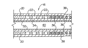
As mentioned above, the proximal shaft section 12 may include a metallic
hypotube 20 formed of a super elastic material such as a nickel titanium
alloy, or
other suitable material such as stainless steel. For example, the hypotube 20
may
comprise nitinol having a length of about 120 - 150 cm and a wall thickness of
about
0.0015 - 0.004 inches. A portion of the distal end of the hypotube 20 may be
removed
to define one or more voids 22. In the example shown, the voids 22 comprise a
helical or spiral slot cut into the wall of the hypotube 20 utilizing a
suitable process
such as laser cutting. The helical slot 22 may have a width of about 0.0002
inches or
more, and may have a pitch which varies linearly from proximal to distal to
gradually
to reduce the stiffness of the hypotube 20. For example, the distal 60 cm may
be laser
cut to define a helical slot 22, with the proximal segment having a pitch that
gradually
reduces from about 0.10 inches to about 0.001 inches, with the remaining
distal
segment having a constant/continuous pitch of about 0.001 inches.
Alternatively, the
pitch may gradually reduce through the distal segment as well.
is Those skilled in the art will recognize that the voids 22 may comprise a
variety
of geometries, including without limitation, a continuous slot as shown, a
series of
slots or holes distributed around the circumference and length of the hypotube
20, etc.
In addition, the voids 22 may extend completely through the wall of the
hypotube 20
or may simply form a recess therein.
2o The distal shaft section 14 may include an inner liner 32 formed of a
lubricious polymer such as PTFE or HDPE. An inner layer 34 comprising a
polymer
such as polyether block amide (e.g., PEBAX) may be placed over the inner liner
32.
The outside diameter of the inner layer 34 may be approximately 0.001 inches
smaller
than the inside diameter of the hypotube 20 to allow the inner liner 32 and
the inner
25 layer 34 to be disposed therein. The inner liner 32 and the inner layer 34
may extend
through the transition region 16 of the hypotube 20, or through the entire
length of the
hypotube 20 including the transition region 16 and the proximal shaft portion
12.
For example, the inner liner 32 and the inner layer 34 may extend through the
entire length of the hypotube 20, with 30 cm extending beyond the distal end
of the
3o hypotube 20. With the assistance of a support mandrel disposed in the lumen
of the
combined inner liner 32 and inner layer 34, the same 32/34 may be inserted
into the
proximal~end of the hypotube 20 and advanced until the distal end thereof
extends 30
cm beyond the distal end of the hypotube 20. As it is being advanced, a
suitable
-3-
CA 02466166 2004-05-05
WO 03/041783 PCT/US02/29540
adhesive such as cyanoacrylate may be applied to the outer surface of the
proximal 10
cm of the inner layer 34 for securement to the inside surface of the proximal
end of
the hypotube 20. At this time, the hub 18 may be connected to the proximal end
of
the hypotube shaft 20.
Optionally, a reinforcement layer 36 such as a single coil, multiple coils, or
multiple interwoven coils (i.e., a braid) may be disposed over the combined
inner liner
32 and inner layer 34 extending beyond the distal end of the hypotube 20. The
reinforcement layer may comprise round wire or rectangular ribbon wire, for
example. A proximal portion of the reinforcement layer 36 may be disposed in
the
to voids 22 to provide a secure, low profile connection to the distal end of
the hypotube
20, and to prevent migration of the reinforcement layer 36. For example, if
the
reinforcement layer 36 comprises a single coil and the voids 22 define a
helical slot,
the coil 36 may be wound into one or more of the distal slots.
Other portions of the distal composite shaft section 30 may be disposed in the
voids 22 in addition to or in place of the coils 36. For example, a portion of
the inner
layer 34 and/or outer layer 38 may be disposed in the voids 22 to modify or
enhance
the connection between the distal composite shaft 30 and the proximal hypotube
shaft
20.
An outer layer 38 formed of a suitable polymeric material may then be placed
over the transition region 16 and the distal shaft section 14, and optionally
over the
proximal shaft section 12 as well. In particular, the outer layer 38 may
extend from a
point 24 on the hypotube 20 proximal of the spiral cut 22 to the terminal end
of the
combined inner liner 32, inner layer 34, and coil reinforcement layer 36. The
outer
layer may be formed of a flexible polymer such as polyether block amide (e.g.,
PEBAX), and may have a gradual transition in flexibility as provided by the
gradient
extrusion process described in co-pending patent application serial number
09/430,327, entitled METHOD AND APPARATUS FOR EXTRUDING
CATHETER TUBING, the entire disclosure of which is hereby incorporated by
reference. By way of example, not limitation, the outer layer 38 may comprise
a
3o polyether block amide (e.g., PEBAX) polymer tube formed by gradient
extrusion,
with a durometer transitioning from 55D to 25D from proximal to distal. The
gradient transition in the outer layer 38 provides superior flexibility,
response, and
control, while contributing to the smooth transition 16 from the relatively
stiff
-4-
CA 02466166 2004-05-05
WO 03/041783 PCT/US02/29540
proximal section 12 to the relatively flexible distal section 14.
Alternatively, the outer
layer 38 may comprise a polymer tube having a continuous durometer, or a
series of
connected polymer tubes having different durometers.
From the foregoing, it will be apparent to those skilled in the art that the
present invention, in one exemplary embodiment, provides an intravascular
microcatheter 10 having a relatively stiff proximal hypotube shaft 20 for
pushability
and torqueability, and a relatively flexible distal composite shaft 30 for
traclcability.
To provide a smooth transition between the relatively stiff proximal shaft 12
and the
relatively flexible distal shaft 14, a transition region 16 is provided by
integrating
l0 portions of the proximal shaft (e.g., spiral cut 22 portion of the hypotube
20) and
portions of the distal shaft (e.g., coil reinforcement 36) in a manner that
provides a
secure connection and that minimizes profile increase.
Those skilled in the art will recognize that the present invention may be
manifested in a variety of forms other than the specific embodiments described
and
contemplated herein. Accordingly, departures in form and detail may be made
without departing from the scope and spirit of the present invention as
described in
the appended claims.
-5-