Note: Descriptions are shown in the official language in which they were submitted.
CA 02466208 2004-05-05
1
SPECIFICATION
METHOD OF CONSTRUCTING UNDERGROUND GALLERY
BY USING PNEUMATIC TRANSFER SYSTEM AND
STRATUM DISPOSAL METHOD
TECHNICAL FIELD
This invention relates to a method of constructing a
stratum disposal site of radioactive waste matter or the like and
l0 tunnels such as mountain tunnels by using a pneumatic
transfer system and also to a method of performing stratum
disposal of the radioactive waste matter or the like.
BACKGROUND ART
In stratum disposal of radioactive waste matter, the
radioactive waste matter is stabilized into vitrified matter, the
vitrified matter is then stored in an airtight condition in a thick
steel plate-made airtight container called an overpack, and the
overpack is then positioned and buried in a bedrock having a
2o depth as much as several hundred to several ten hundred meter
underground, for instance, through a buffer material
(bentonite-contained mixed soil or the like).
Fig. 18 shows one exemplified stratum disposal site,
which is composed of access galleries 2 (vertical shafts 2a,
inclined shafts 2b and spiral galleries) that interconnect ground
facilities 1 and underground facilities, a large number of
disposal galleries 3 that are to position the waste matter
(overpack), main galleries 4 that run round the disposal
CA 02466208 2004-05-05
2
galleries and transfer galleries 5 that interconnect the main
galleries. Incidentally, a disposal panel 6 is constructed as a
divisional unit composed of the disposal gallery 3 and the main
gallery 4 that runs round the above disposal gallery The
advantages of dividing an area for disposal of the waste matter
into several independent panels are that flexible layout may be
effected depending on geological environmental conditions or
the like of the disposal site to ensure that principal works such
as construction, operation and closing-up are executable
l0 independently in parallel on each panel basis.
In the stage of construction, the construction of the
underground facilities and the ground facilities takes place. In
the stage of operation, works such as accepting of the vitrified
matter, charging of the overpack with the vitrified matter,
manufacturing of the buffer material, carrying and positioning
of the waste matter and the buffer material and refilling of the
disposal galleries and the main galleries mainly take place. In
the stage of closing-up, works such as refilling of the transfer
galleries and the access galleries and disassembling and
dismantling of the ground facilities mainly take place.
In the above stratum disposal site, methods
conventionally available as a method of carrying the waste
matter and the buffer material from the ground to the
underground site and a method of positioning the waste matter
and the buffer material in a disposal space are as follows.
Incidentally, there are provided Japanese Patent Laid-open Nos.
2001-166093, 9-61594, 9-61595 and 9-61596 etc. as the
reference to documents on the related art.
CA 02466208 2004-05-05
3
(1) Method of carrying waste matter and buffer material
(See Fig. 18)
(a) Method (of vertical shaft system) of carrying waste
matter A and a buffer material B from the ground to the
underground site by using an individual lifting equipment 50 in
each access vertical shaft 2a
(b) Method (of inclined shaft system) of carrying the
waste matter A and the buffer material B from the ground to the
underground site by using an individual travelling carrying
l0 machine 51 that travels through each access inclined shaft 2b
(2) Method of positioning waste matter and buffer material
(See Fig. 18)
Fig. 18 shows a pattern of lengthwise arrangement of
disposal holes, wherein a plurality of vertical disposal holes '7
are constructed in the bottom of the disposal gallery 3 at
intervals in a longitudinal direction of the gallery, and the waste
matter A is positioned and buried in a lengthwise arrangement
in each disposal hole 7. The waste matter A and the buffer
material (block) B are carried after being transshipped into an
2o individual automatic remote control positioning apparatus 5,
and positioning takes place in such a manner that ~l a lower
buffer material block B is firstly positioned in each disposal hole
7 by using a remote control robot (a handling device) of the
automatic remote control positioning apparatus 52, ~2 the
waste matter A is then positioned in the buffer material block B,
given by the above positioning, by using the remote control
robot, and O an upper buffer material block B is then
positioned on the waste matter A by using the remote control
CA 02466208 2004-05-05
4
robot.
Incidentally, other waste matter positioning and burying
patterns than the above pattern of lengthwise arrangement of
disposal holes include patterns such as a pattern of horizontal
arrangement of disposal galleries, wherein horizontal or
inclined disposal galleries are constructed by excavation in
parallel at prescribed intervals between a pair of main galleries
at the left and right sides, and the waste matter A is positioned
and buried in a horizontal arrangement in each disposal gallery
at prescribed intervals in the longitudinal direction of the
gallery, a pattern of lengthwise arrangement of disposal vertical
shafts, wherein vertical disposal galleries (disposal vertical
shafts) are constructed by excavation in parallel at prescribed
intervals between the main gallery at the upper side and the
gallery at the lower side, and the waste matter A is positioned
and buried in a lengthwise arrangement in each disposal gallery
at prescribed intervals in a vertical direction, and a pattern of
horizontal arrangement of disposal holes, wherein horizontal
disposal holes are constructed by excavation in the opposite side
wall parts of the disposal gallery at intervals in the longitudinal
direction of the gallery, and the waste matter A is positioned and
buried in a horizontal arrangement in each disposal hole.
In addition, the buffer material B includes mixed soil or
the like mainly containing bentonite. The bentonite-contained
mixed soil is a material having dynamic buffering functions, low
permeability and low diffusibility of radioactive matter, in other
words, a material that is effective in reducing bedrock pressure
or underground water effects to ensure that retardation of
CA 02466208 2004-05-05
nuclide migration is achievable.
(1) Problems of the conventional method of carrying the
waste matter and the buffer material
5 (a) In the case of the vertical shaft system, there is a
possibility of bringing about a fall of the waste matter A. The
fall of the waste matter, if caused, is likely to lead to serious
disasters.
(b) In the case of the vertical shaft system, a dead load
of a wire rope of the lifting equipment 50 increases with greater
shaft depth, so that a remarkable reduction in permissible
lifting capacity (a waste matter weight obtained by taring the
rope dead load) is caused.
(c) In the case of the vertical shaft system, it is
difficult to increase a lifting speed, because of the possibility of
being in danger of the fall of the waste matter A and the
necessity to decrease a load applied to the wire rope.
(d) In the case of the inclined shaft system,
application of a load to a speed reduction (stopping) device of the
traveling carrying machine 51 is caused. When the speed
reduction device develops troubles, there is a fear that runaway
of the waste matter A occurs, leading to serious disasters.
(e) In the case of the inclined shaft system, an
increase of reliability on control of the traveling carrying
machine 51 requires an expensive machine.
(fj In the case of the inclined shaft system,
arrangements of the secondary equipment such as rail and
traction wire arrangements are required, leading to an increase
CA 02466208 2004-05-05
6
in cost.
(2) Problems of the conventional method of positioning the
waste matter and the buffer material
(a) An extremely precise automatic remote control
positioning apparatus 52 is required for execution of individual
positioning of the waste matter A and the buffer material B in
the disposal holes or the like, leading to an increase in cost.
(b) If the positioning results in a failure, it is difficult
to effect restoration by an automatic remote control operation.
l0 (c) For the positioning of the buffer material blocks in
the disposal holes or the like in such a manner as to divide the
buffer material into blocks, it is difficult to secure a buffer
material quality obtained after the positioning of the buffer
material.
While the above problems are those given in the stage of
operation, the same problems as those shown in the above
section (1) are also created in the stage of construction of the
disposal galleries, since the carrying-out of the excavation chips
and the carrying-in of the materials and equipment for
2o construction of the disposal galleries are effected also by using
the lifting equipment 50 or the traveling carrying machine 52 in
the access galleries 2 in the stage of construction.
DISCLOSURE OF THE INVENTION
The present invention has been undertaken in order to
eliminate the above problems, and an object of the present
invention is to provide a method of constructing underground
galleries, wherein in constructing disposal galleries in a
CA 02466208 2004-05-05
7
stratum disposal site or tunnels such as mountain tunnels, the
carrying-out of excavation chips or the like and the carrying-in
of materials and equipment or the like may be effected safely,
quickly and reliably at low cost, and also a stratum disposal
method, wherein the carrying-in of waste matter in the stratum
disposal site may be effected safely, quickly and reliably at low
cost, the positioning of the waste matter and a buffer material
in the stratum disposal site may be also effected safely, quickly
and reliably at low cost, and the quality of the buffer material
may be secured easily.
According to Claim 1 of the present invention, there is
provided a method of constructing underground galleries by
using a vertical shaft or an inclined shaft, specifically, a method
of constructing underground galleries, wherein an air carrying
pipeline is used while extending the air carrying pipeline
downwards as desired during excavation of the vertical shaft or
the inclined shaft so as to carry out vertical shaft or inclined
shaft excavation chips to the ground and also carry in materials
and equipment for the vertical shaft or the inclined shaft to the
underground site, and by using the air carrying pipeline
extending from the vertical shaft or the inclined shaft to an
underground gallery, excavation chips from the underground
gallery are carried out to the ground or the materials and
equipment for the underground gallery are carried in to the
underground site. In the underground galleries, the air
carrying pipeline is used for both of the carrying-out of the
excavation chips and the carrying-in of the materials and
equipment, or alternatively, for either of the carrying-out of the
CA 02466208 2004-05-05
excavation chips or the carrying-in of the materials and
equipment.
The construction method according to Claim 1 of the
present invention is a method, which is applied to construction
of the underground galleries in the stratum disposal site of the
waste matter and the mountain tunnels or the like, and in
which the air carrying pipeline is arranged in the vertical shaft
or the inclined shaft, and by using the air carrying pipeline and
a carrying container (a so-called capsule transport line), the
to carrying-out of the excavation chips from the vertical shaft, the
inclined shaft or the underground gallery to the ground, and the
carrying-in of the materials and equipment including the spray
concrete for the vertical shaft, the inclined shaft or the
underground gallery to the underground site are effected (See
Fig. 1). Alternatively, in the underground galleries, other
paths or other carrying means are also available for the
carrying-out of the excavation chips or the carrying-in of the
materials and equipment.
According to Claims 2 of the present invention, there is
provided a method of constructing underground galleries by
using a vertical shaft or an inclined shaft, specifically, a method
of constructing underground galleries, wherein the vertical
shaft or inclined shaft itself constructed by excavation is used as
an air carrying pipeline, and by using the air carrying pipeline,
excavation chips from the underground gallery are carried out
to the ground or materials and equipment for the underground
gallery are carried in to the underground site. In the above
construction method, the air carrying pipeline is also used in the
CA 02466208 2004-05-05
9
underground galleries for both of the carrying-out of the
excavation chips and the carrying-in of the materials and
equipment, or alternatively, either of the carrying-out of the
excavation chips or the carrying-in of the materials and
equipment.
The construction method according to Claim 2 of the
present invention is a method, which is applied to construction
of the underground galleries in the stratum disposal site of the
waste matter and the mountain tunnels or the like, and in
l0 which the air carrying pipeline is constructed in such a manner
that the vertical shaft or the inclined shaft for air carrying is
constructed by excavation and a lining material and a
membrane or the like respectively adapted to bear a strength
and an air-tightness are then placed on the inner side wall of
the vertical shaft or the inclined shaft, and by using the vertical
shaft-and-air carrying pipeline and the carrying container (the
so-called capsule transport line), the carrying-out of the
excavation chips from the vertical shaft, the inclined shaft or
the underground gallery to the ground, and the carrying-in of
the materials and equipment including the spray concrete for
the vertical shaft, the inclined shaft or the underground gallery
to the underground site are effected (See Fig. 2). Alternatively,
other paths or other carrying means are also available for the
carrying-out of the excavation chips or the carrying-in of the
materials and equipment in the underground galleries.
According to Claim 3 of the present invention, there is
provided a stratum disposal method of performing stratum
disposal of waste matter in an underground disposal space,
CA 02466208 2004-05-05
specifically, a stratum disposal method, wherein an air carrying
pipeline is arranged in an access vertical shaft or an access
inclined shaft extending to an underground gallery, and by
using the air carrying pipeline, the waste matter is carried in to
5 the underground gallery for positioning and burying of the
waste matter in the disposal space.
The stratum disposal method according to Claim 3 of the
present invention is a method, which is applied to disposal of
the waste matter (the so-called overpack) such as radioactive
l0 wastes, for instance, by positioning and burying the waste
matter, together with the buffer material, in the underground
disposal space (a disposal gallery or disposal holes provided for
the disposal gallery or the like), and in which the air carrying
pipeline is arranged in the access vertical shaft or the access
inclined shaft, and by using the air carrying pipeline and the
carrying container (the so-called capsule transport line), the
carrying-in of the waste matter to the underground gallery is
effected (See Fig. 1). The air carrying pipeline and an
automatic remote control positioning apparatus or the like may
be used for the carrying of the waste matter to the disposal
space to ensure that the waste matter is positioned and buried,
together with the buffer material, in the disposal space.
According to Claim 4 of the present invention, there is
provided a stratum disposal method of performing stratum
disposal of waste matter in an underground disposal space,
specifically, a stratum disposal method, wherein a vertical shaft
or an inclined shaft itself constructed by excavation is used as
an air carrying pipeline, and by using the air carrying pipeline,
CA 02466208 2004-05-05
11
the waste matter is carried in to the underground gallery, for
positioning and burying of the waste matter in the disposal
space.
The stratum disposal method according to Claim 4 of the
present invention is a method, which is applied to disposal of
the waste matter (the so-called overpack) such as the
radioactive waste, for instance, by positioning and burying the
waste matter, together with the buffer material, in the
underground disposal space (the disposal gallery or the disposal
l0 holes provided for the disposal gallery), and in which the air
carrying pipeline is constructed in such a manner that the
vertical shaft or the inclined shaft for air carrying is constructed
by excavation and a lining material and a membrane or the like
respectively adapted to bear a strength and an air-tightness are
placed on the inner side wall of the vertical shaft or the inclined
shaft, and by using the vertical shaft-and-air carrying pipeline
and the carrying container (the so-called capsule transport line),
the carrying-in of the waste matter to the underground gallery
is effected (See Fig. 2). The air carrying pipeline and the
automatic remote control positioning apparatus or the like may
be used for the carrying of the waste matter to the disposal
space to ensure that the waste matter is positioned and buried,
together with the buffer material, in the disposal space.
According to Claim 5 of the present invention, in the
stratum disposal method according to Claim 3 or 4, there is
provided the stratum disposal method, wherein a carrying
matter obtained by integrating the waste matter and the buffer
material together is carried by pneumatic transfer, and is
CA 02466208 2004-05-05
12
positioned and buried in a disposal space.
Specifically, according to the present invention, while the
waste matter (the so-called overpack) itself may be carried by
pneumatic transfer or the carrying container with the waste
matter stored therein may be also carried by pneumatic transfer,
it is preferable that the waste matter and the buffer material
are stored in an integrating container, and the pneumatic
transfer of the integrating container is effected with the
integrating container stored in the carrying container or with
the integrating container as the carrying container to position
and bury the integrating container in the disposal space.
According to Claim 6 of the present invention, in the
stratum disposal method according to Claim 1, 2, 3, 4 or 5, there
is provided the stratum disposal method, wherein the air
carrying pipeline has, at a lower part, an air valve which
permits the inflow of air into the pipeline and checks the
outflow of air to the outside of the pipeline.
Specifically, for a pneumatic transfer system according to
the present invention, while use is made of systems such as a
suction system, wherein an exhaust device is arranged at an
upper part of the air carrying pipeline, a press-in system,
wherein an exhaust device is arranged at a lower part of the air
carrying pipeline, and a system, wherein the exhaust device is
arranged at both of the upper and lower parts of the air carrying
pipeline, a pneumatic transfer system having the air valve of
check valve type at the lower part of the air carrying pipeline is
effective in performing supply of air into the pipeline or
ventilation of the underground facilities and the tunnels
CA 02466208 2004-05-05
13
efficiently in a valve opened condition, and also enables a
pneumatic damper effect to be obtained in a valve closed
condition. Thus, even if troubles or the like with the system
bring about a spontaneous fall condition, the damper effect is
expected to be active, with the result that the safety is secured.
Incidentally, according to the present invention, the
vertical shaft is a shaft constructed in a vertical position by
excavation, and the inclined shaft includes a linear-shaped or
partly curved shaft constructed in an inclined position by
excavation.
In the present invention, since (1) the pneumatic transfer
system is used to carry out and carry in the carrying matter
using a difference between pneumatic pressures at the upper
and lower sides of the carrying matter, ~l it is allowable to
dispense with the conventional wire rope so that any restriction
by a depth is eliminated to ensure that carrying even to a
greater depth is executable, 2O a carrying speed may be
increased as compared with a conventional wire rope system, ~3
the transfer system requires only the differential pressure
2o management, leading to an increase in carrying reliability, ~ a
transfer system mechanism is simple, so that high resistance to
troubles is obtainable, and maintenance or management thereof
also becomes facilitated, and 05 there is no necessity of a
precise carrying machine, resulting in an increase in economical
efficiency. With the above advantages, the carrying-out of the
excavation chips or the like and the carrying-in of the materials
and equipment or the like in construction of the stratum
disposal site and the mountain tunnels or the like, and the
CA 02466208 2004-05-05
14
carrying-in of the waste mater in the stratum disposal site and
the positioning of the waste matter and the buffer material in
the stratum disposal site may be effected safely, quickly and
reliably at low cost.
(2) With the operation of the pneumatic transfer
system, it is allowable to perform suction of air in the
underground facilities or the tunnels to ensure that ventilation
of air in the underground facilities or the tunnels is achievable.
The air carrying pipeline is also serviceable as a ventilating
l0 vertical shaft, and thus requires no arrangement of other
ventilation systems, leading to an increase in economical
efficiency
(3) With the use of the vertical shaft or the like itself
as a part of the pneumatic transfer system, Ol the air carrying
pipeline having the strength and the air-tightness may be
constructed easily only by placing the lining material and the
membrane or the like on the inner side wall of the vertical shaft
or the like, and ~ a compact transfer system may be given to
ensure that a diameter reduction of the vertical shaft or the like
is attainable. The above advantages lead to an increase in
economical efficiency
(4) The carrying container is put to practical use in
the stratum disposal of the radioactive waste matter, and the
waste matter and the buffer material are integrated together at
the ground facilities. By positioning and burying the
integrated waste matter and buffer material in the disposal
space of the underground facilities together with the carrying
container, ~l there is no necessity to position the waste matter
CA 02466208 2004-05-05
A and the buffer material B individually in the underground site,
unlike a conventional technology, so that the positioning work
may be effected safely, quickly and reliably at low cost, and the
positioning reliability and the quality of the buffer material are
5 increased. ~ No swelling of the buffer material is caused
because of no permeation of the underground water in the
buffer material for a certain period of time since the positioning
of the buffer material, so that retrieving becomes facilitated,
and a removal work is also performed easily
l0 (5) With the air valve provided at the lower part of the
air carrying pipeline, the outflow of air from the vertical shaft or
the like into the underground facilities or the tunnels is
prevented, so that even if a stop of the power supply or the like
in the course of carrying brings about the spontaneous fall
15 condition of the carrying matter, the damper effect obtained by a
compression action of air at the lower part of the air carrying
pipeline may be adapted to prevent disasters caused by a crash
of the carrying matter against the lower part of the
underground facilities or the like.
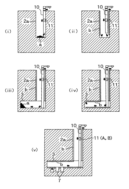
BRIEF DESCRIPTION OF THE DRAWINGS
Fig. 1 is a sectional view showing one embodiment of a
constructing method and a stratum disposal method according
to the present invention, specifically, a construction stage and
an operation stage in progress order when an air carrying
pipeline is placed in an access vertical shaft of a stratum
disposal site, wherein Figs. 1(i) and (ii) show stages of
construction of a vertical shaft, Figs. 1(iii) and (iv) show stages
CA 02466208 2004-05-05
16
of construction of a horizontal gallery and Fig. 1(v) shows a
stage of operation;
Fig. 2 is a sectional view showing one embodiment of a
constructing method and a stratum disposal method according
to the present invention, specifically, a construction stage and
an operation stage in progress order when an individual vertical
shaft is used as the air carrying pipeline, wherein Fig. 2(i)
shows a stage of construction of a vertical shaft, Figs. 2(ii) and
(iii) show stages of construction of a horizontal gallery, and Fig.
2(iv) shows a stage of operation;
Fig. 3 is a sectional view showing an outline of the whole
pneumatic transfer system for use in the present invention;
Fig. 4 is a partially enlarged sectional view showing the
air carrying pipeline of Fig. 3;
Fig. 5 is a partially enlarged sectional view showing an
open condition and a closed condition of an air valve of Fig. 3;
Fig. 6 is a schematic perspective view showing a
ventilating system obtained by the individual vertical shaft of
Fig. 2;
Fig. 7 is a sectional view showing one embodiment of a
carrying container carrying-in process;
Fig. 8 is a sectional view showing one embodiment of a
carrying matter structure;
Fig. 9 is a sectional view showing a different embodiment
of the carrying matter structure;
Fig. 10 is a sectional view showing a different
embodiment of carrying matter;
Fig. 11 is a sectional view showing a work of positioning
CA 02466208 2004-05-05
17
of the carrying matter in a disposal hole in progress order;
Fig. 12 is a sectional view showing the carrying container
and the carrying matter;
Fig. 13 is a sectional view showing a different
embodiment of a carrying matter shape;
Fig. 14 is a sectional view showing a deformed condition
of the vertical shaft;
Fig. 15 is a sectional view showing one embodiment of a
carrying material position in the carrying matter;
Fig. 16 is a sectional view showing a different
embodiment of the vertical shaft;
Fig. 17 is a sectional view showing one embodiment of a
lower part shape of the vertical shaft; and
Fig. 18 is a perspective view and a sectional view showing
a stratum disposal site of radioactive waste matter and a
conventional carrying and positioning method.
BEST MODE OF CARRYING OUT THE INVENTION
Hereinafter, the present invention will be described with
reference to an illustrated embodiment. The embodiment of
the present invention is that attained by applying the present
invention to stratum disposal of radioactive waste matter. Fig.
1 shows a construction stage and an operation stage in order
when an air carrying pipeline is placed in an access vertical
shaft of a stratum disposal site. Fig. 2 shows a construction
stage and an operation stage in order when an individual
vertical shaft is used as the air carrying pipeline. Fig. 3 shows
an outline of a pneumatic transfer system for use in the present
CA 02466208 2004-05-05
18
invention.
[A] For placement of the air carrying pipeline in the access
vertical shaft of the stratum disposal site
(1) This stage is that of construction of the vertical shaft, and
as shown in Fig. 1 (i), an air carrying pipeline 10 is placed in a
vertical position, while an access vertical shaft 2a is constructed
by excavation from the ground. The pipeline 10 is extended
downwards successively with the advance of construction of the
vertical shaft 2a by excavation. Then, excavation chips a are
1o stored in a carrying container (capsule) 11 and are then carried
out to the ground by pneumatic transfer of suction system with
negative pressure or of press-in system with positive pressure.
(2) This stage is also that of construction of the vertical shaft,
and as shown in Fig. 1(ii), materials and equipment including
spray concrete b are stored in the carrying container 11 and are
then carried in from the ground to the bottom of the vertical
shaft 2a under excavation by pneumatic transfer of suction or
press-in system. The carrying-out of the excavation chips a
and the carrying-in of the materials and equipment b take place
in an alternate manner to proceed the execution of work of the
spray concrete b to an upper part of the vertical shaft while
advancing the excavation.
(3) This stage is that of construction of the horizontal gallery,
and as shown in Fig. 1 (iii), the excavation chips a from a
disposal gallery 3 are stored in the carrying container 11 and
are then carried out to the ground by pneumatic transfer of
suction or press-in system.
(4) This stage is also that of construction of the horizontal
CA 02466208 2004-05-05
19
gallery, and as shown in Fig. 1(iv), the materials and equipment
including the spray concrete b for the disposal gallery 3 are
stored in the carrying container 11 and are then carried in from
the ground into the disposal gallery 3 at the bottom of the
vertical shaft 2a by pneumatic transfer of suction or press-in
system.
Incidentally, in the stage of construction of the horizontal
gallery, other paths such as the vertical shafts and the galleries
or other carrying means are also available for the carrying-out
l0 of the excavation chips a or the carrying-in of the materials and
equipment.
(5) This stage is that of operation, and as shown in Fig. 1 (v),
waste matter A and a buffer material B are stored in the
carrying container 11 and so on (as will be described later) and
are then carried in from the ground into the disposal gallery 3
by pneumatic transfer of suction or press-in system to ensure
that the waste matter A is positioned and buried in a disposal
hole 7.
Specifically, transfer of the waste matter for positioning
may take place also using an automatic remote control
positioning apparatus or the like. Or alternatively, it is also
allowable to apply the air carrying pipeline 10 to the transfer of
the waste matter for positioning in such a manner as to place
the air carrying pipeline 10 also in the disposal gallery 3.
The air carrying pipeline 10 is also serviceable as an
exhaust shaft for ventilation of the underground facilities as
will be described later, and thus requires no arrangement of
other ventilation systems, leading to an increase in economical
CA 02466208 2004-05-05
efficiency.
[B] For use of an individual vertical shaft as the air carrying
pipeline
(1) This stage is that of construction of the vertical shaft, and
5 as shown in Fig. 2(i), an individual vertical shaft 12 for carrying
is constructed with a raise boring machine or the like for use in
a rising construction method. A lining material and a
membrane are given to an inside surface of the vertical shaft 12
constructed by excavation, as will be described later, and the
to vertical shaft 12 is used as an air carrying pipeline 13. The
individual vertical shaft 12 for carrying is also served as a
ventilating vertical shaft, as will be described later.
(2) This stage is that of construction of the horizontal gallery,
and as shown in Fig. 2(ii), the excavation chips a from the
15 disposal gallery 3 are stored in the carrying container 11 and
are then carried in to the ground by pneumatic transfer of
suction or press-in system by using the air carrying pipeline 13
obtained by the individual vertical shaft.
(3) This stage is also that of construction of the horizontal
20 gallery, and as shown in Fig. 2(iii), the materials and equipment
including the spray concrete b for the disposal gallery 3 are
stored in the carrying container 11 and are then carried in from
the ground into the disposal gallery 3 by pneumatic transfer of
suction or press-in system by using the air carrying pipeline 13
obtained by the individual vertical shaft.
Incidentally, in the stage of construction of the horizontal
gallery, other paths such as the vertical shafts and the galleries
or other carrying means are also available for the carrying-out
CA 02466208 2004-05-05
21
of the excavation chips a or the carrying-in of the materials and
equipment.
(4) This stage is that of operation, and as shown in Fig. 2(iv),
the waste matter A and the buffer material B are stored in the
carrying container 11 and so on (as will be described later) and
are then carried in from the ground into the disposal gallery 3
by pneumatic transfer of suction or press-in system by using the
air carrying pipeline 13 obtained by the individual vertical shaft
to ensure that the waste matter A is positioned and buried in
to the disposal hole 7.
Specifically, the transfer of the waste matter for
positioning in this case may take place also using the automatic
remote control positioning apparatus or the like. Or
alternatively, it is also allowable to apply the air carrying
pipeline 10 to the transfer of the waste matter for positioning in
such a manner as to place the air carrying pipeline 10 also in
the disposal gallery 3.
With the use of the vertical shaft itself as a part of a
pneumatic transfer system as described the above, O the air
2o carrying pipeline having the strength and the air-tightness may
be constructed only by placing the lining material and the
membrane on the inner side wall of the vertical shaft. ~ The
compact transfer system may be given to ensure that a vertical
shaft diameter reduction is attainable. The above advantages
lead to an increase in economical efficiency. 3~ The vertical
shaft 12 itself is also serviceable as the exhaust shaft for
ventilation of the underground facilities as will be described
later, and thus requires no arrangement of other ventilation
CA 02466208 2004-05-05
22
systems, leading to an increase in economical efficiency.
[C] Pneumatic transfer system
Figs. 3 to 5 show an embodiment of the air carrying
pipeline 13 applied to the above case [B], and the air carrying
pipeline 13 having the strength and the air-tightness is
constructed by giving a lining material (such as concrete) 14 and
a membrane (such as a stainless steel plate) 15 to an inner wall
surface of the individual vertical shaft 12 constructed by
excavation of a bedrock. It is noted that the air carrying
l0 pipeline 10 applied to the above case [A] is constructed by
connecting steel pipe units together.
An exhaust device 16 such as a blower is placed at an
upper part of the air carrying pipeline 13 (or 10), and an air
valve 17 is provided at a lower part thereof to control a carrying
speed (an ascend speed and a descend speed) of the carrying
container 11 by managing a difference between pneumatic
pressures at the upper and lower sides of the carrying container
11 in such a manner as to effect the exhaust of air through the
upper part and the suction of air through the lower part.
2o Although the illustrated embodiment employs the negative
pressure suction system, the present invention is not limited to
the above system, and a positive pressure press-in system with
the blower or the like arranged at the lower part or a system
with the blower or the like arranged at both of the upper and
lower parts is also available.
With the above pneumatic transfer system, ~l it is
allowable to dispense with the wire rope required for the
conventional vertical shaft system so that any restriction by a
CA 02466208 2004-05-05
23
depth is eliminated to ensure that carrying even to the greater
depth is executable. 2~ A carrying speed is increased. ~3 The
transfer system is simple because of only the need for the
differential pressure management, leading to an increase in
carrying reliability. ~ A transfer system mechanism is simple,
so that high resistance to troubles is obtainable and the
maintenance or management thereof becomes facilitated. ~5
There is no necessity of a precise carrying machine, resulting in
an increase in economical efficiency
As shown in Fig. 5, the air valve 17 is a kind of check
valve and has a structure in which an opened condition is
automatically given by the flow of air created at the time of
carrying to ensure that the inflow of air from the underground
facilities to the air carrying pipeline 13 is permitted, while a
closed condition is automatically given by the reverse flow of air
created at the time of system troubles or spontaneous falling to
ensure that the outflow of air from the air carrying pipeline 13
to the underground facilities is prevented.
Thus, OO with the operation of the pneumatic transfer
2o system, the air valve 17 is opened automatically to effect the
suction of air in the underground facilities for the exhaust to the
ground, thereby enabling the ventilation in an administrative
area of the underground facilities, as shown in Fig. 6. In other
words, the individual vertical shaft 12 for carrying is also
serviceable as the ventilating vertical shaft, and thus requires
no arrangement of other ventilating systems, leading to an
increase in economical efficiency ~2 Even if a stop of the
power supply or the like in the course of carrying brings about a
CA 02466208 2004-05-05
24
spontaneous fall condition of the carrying container 11 or the
like, the reverse flow of air allows the air valve 17 to be closed
automatically to ensure that a compression action (a vertical
shaft damper effect) of air in an airtight condition at the lower
part of the vertical shaft is adapted to prevent disasters caused
by a crash of the waste matter A against the lower part of the
facilities. In other words, a failsafe function is secured.
As shown in Fig. 3, the air carrying pipeline 13 has also,
at the upper and lower parts, detachable devices 18. The
upper and lower parts of the air carrying pipeline 13 are
respectively composed of steel pipes, and loading and unloading
of the carrying container 11 or the like are effected in such a
manner as to horizontally slide movable steel pipes for the
above steel pipes using a traverse carriage and so on.
Fig. 7 shows an embodiment of a carrying container-11
carrying-in process. (1) The carrying container 11 with the
materials and equipment, the waste matter or the buffer
material or the like stored therein is inserted into the upper
detachable device 18, and this upper detachable device 18 is
then set at the upper part of the air carrying pipeline 13. (2)
The exhaust device 16 is operated to carry the carrying
container 11 to the underground site, while managing the
difference between the pneumatic pressures at the upper and
lower sides of the carrying container 11. (3) The lower
detachable device 18 is detached from the lower part of the air
carrying pipeline 13 to take out the carrying container 11 from
the lower detachable device 18.
[D] Waste matter and buffer material
CA 02466208 2004-05-05
Figs. 8 to 10 show various kinds of carrying matter forms.
Figs. 8 and 9 show a case where the carrying of the waste
matter A (overpack) and the buffer material (bentonite-
contained mixed soil) B that are integrated together is effected,
5 and the integrated waste matter A and buffer material B are
positioned and buried. In the case shown in Fig. 8, the waste
matter A and the buffer material B are stored in an integrating
container 20 at the ground facilities, and the carrying of the
integrating container 20 is effected with the integrating
l0 container 20 further inserted into the carrying container 11. In
the case shown in Fig. 9, the waste matter A and the buffer
material B are stored in the integrating container 20 at the
ground facilities, and the carrying of the integrating container
20 is effected as it is with the integrating container 20 as the
15 carrying container 11.
The carrying matter form is not limited to the above
forms, and it is also allowable to carry the waste matter A as it
is without using the carrying container, as shown in Fig. 10.
Further, the carrying of the waste matter A may be also effected
20 with the waste matter A stored in the carrying container 11. In
this case, the carrying of the buffer material B is effected
separately with the buffer material B stored in the carrying
container 11.
In addition, spacers 21 such as wheels mounted to an
25 outer circumference of the carrying container 11 as shown in Fig.
8 are effective in preventing the membrane of the air carrying
pipeline from being damaged by the container during the
carrying, leading to an increase in pneumatic transfer system
CA 02466208 2004-05-05
26
durability. Further, a seal material is provided on the outer
circumference of the carrying container 11 as needed.
In use of the carrying container 11 shown in Fig. 8,
removal of the integrating container 20 from the carrying
container 11 is effected, and this integrating container 20 is
positioned and buried in the disposal hole 7 as it is, as shown in
Fig. 11. In use of the carrying container 11 shown in Fig. 9, the
received integrating container 20 serving also as the carrying
container is also positioned and buried in the disposal hole 7 as
it is.
With the use of the integrating container in which the
waste matter A and the buffer material B are integrated
together as described the above, ~ there is no necessity to
position the waste matter A and the buffer material B
individually in the underground site, unlike the conventional
technology, so that the positioning work may be effected safely,
quickly and reliably at low cost, and the positioning reliability
and the buffer material quality are increased. 2~ With the
integrating container 20 positioned in the disposal hole 7 as it is,
2o no swelling of the buffer material is caused because of no
permeation of the underground water into the buffer material B
during the period of operation (until a period of time when a
corrosion hole is caused in the integrating container), so that
the retrieving during the above period becomes facilitated. Also,
the removal for each integrating container 20 may be easily
performed.
Alternatively, it is also allowable to carry the waste
matter A and the buffer material B individually by pneumatic
CA 02466208 2004-05-05
27
transfer, without being limited to the carrying of the waste
matter A and the buffer material B that are integrated together.
When the carrying of the waste matter A is effected as it is as
shown in Fig. 10, a further inside diameter reduction of the
individual vertical shaft 12 or the like is obtainable. For the
individual carrying of the waste matter A and the buffer
material B using the carrying container 11, the carrying of the
waste matter A and the buffer material B is effected with an
upper buffer material B1, the waste matter A and a lower buffer
l0 material B2 stored in three pieces of carrying containers 11
respectively, for instance, as shown in Fig. 12. Then, the
positioning is effected in such a manner that the lower buffer
material B2 is firstly positioned in the disposal hole 7, the waste
material A is then positioned, and the upper buffer material B1
is then positioned on the waste matter A. In the stage of
construction, the carrying of the excavation chips or the
materials and equipment including the spray concrete may be
effected with the excavation chips or the materials and
equipment stored in the carrying container 11.
2o Fig. 13 shows an embodiment of a pneumatic transfer
system that is independent of a vertical accuracy of the vertical
shaft 12. It is possible to attain the carrying independent of an
accuracy of excavation to a perpendicularity of the vertical shaft
in such a manner as to provide a structure in which the carrying
matter such as the carrying container 11 and the waste matter
A makes contact with the membrane 15 around the carrying
matter only through a plane including a section perpendicular
to the vertical shaft 12, in other words, form the carrying
CA 02466208 2004-05-05
28
matter in a spherical or oval shape, for instance.
Even if the vertical shaft 12 is in a somewhat vertically
deformed condition as shown in Fig. 14, the carrying of the
carrying matter may be effected safely in such a manner as to
form the carrying matter in the spherical or oval shape or the
like. Further, the increased stability during the carrying and
at the time of landing is provided by locating the center of
gravity of the carrying matter at a position lower than a point of
contact of the carrying matter with the membrane in such a
1o manner as to place the waste matter A at the lower part of the
carrying container 11, as shown in Fig. 15.
Alternatively, the individual vertical shaft 12 for
carrying need not extending perpendicularly, and may be an
inclined or partially curved shaft (with a curve whose radius of
curvature is as much as permitting passage of the carrying
container or the like), as shown in Fig. 16.
Further, with the use of the vertical shaft damper effect
at its maximum, the carrying in a spontaneous fall condition
may be also effected. When a method of carrying in the
spontaneous fall condition is adopted, it is also allowable to
increase the damper effect in such a manner as to fill the
vertical shaft with liquid such as water. While the vertical
shaft damper effect provides a high failsafe against the fall of
the carrying matter, the further increased safety may be
provided by gradually reducing the lower part diameter of the
vertical shaft 12, as shown in Fig. 17.
The differential pressure management applied to a case
where the carrying matter is lightweight (the carrying device is
CA 02466208 2004-05-05
29
capable of being lifted with the atmospheric pressure) is limited
to the suction system (with the negative pressure). On the
other hand, the differential pressure management applied to a
case where the carrying matter is heavy is limited to the press-
in system (with the positive pressure).
While the foregoing description relates to the stratum
disposal site, it is to be understood that the present invention is
not limited to the stratum disposal site, and it is allowable to
apply the pneumatic transfer system of the present invention
also to construction of the tunnels such as the mountain tunnels.
While the stratum disposal of the radioactive waste matter in
the mode of positioning with the disposal holes has been
described, it is to be understood that the present invention is
not limited to the above positioning mode, and it is, of course,
allowable to apply the present invention to other positioning
modes. It is also to be understood that the present invention is
not limited to the burying disposal of radioactive waste matter,
and it is also allowable to apply the present invention to the
burying disposal of other waste matters.
2o The present invention has the above arrangements, and
therefore, the following effects may be obtained.
(1) Since the present invention employs the pneumatic
transfer system for carrying of the excavation chips, the
materials and equipment, the waste matter and the buffer
material or the like to carry out and carry in the carrying mater
by using the difference between the pneumatic pressures at the
upper and lower sides of the carrying matter, ~l it is allowable
to dispense with the conventional wire rope so that any
CA 02466208 2004-05-05
restriction by the depth is eliminated to ensure that the
carrying to the greater depth is executable, ~2 the carrying
speed may be increased as compared with that of the
conventional wire rope system, 0 the transfer system requires
5 only the differential pressure management, leading to the
increase in carrying reliability, ~ the transfer system
mechanism is simple, so that high resistance to the troubles is
obtainable and the maintenance or management thereof
becomes facilitated, and ~5 there is no necessity of the precise
l0 carrying machine, resulting in the increase in economical
efficiency. With the above advantages, the carrying-out of the
excavation chips or the like and the carrying-in of the materials
and equipment in constructing the stratum disposal site and the
mountain tunnels or the like, the carrying-in of the waste
15 matter in the stratum disposal site, and the positioning of the
waste matter and the buffer material in the stratum disposal
site may be effected safely, quickly and reliably at low cost.
(2) With the operation of the pneumatic transfer system, it is
allowable to effect the suction of air in the underground
20 facilities or the tunnels to ensure that the ventilation in the
underground facilities or in the tunnels is achievable. The air
carrying pipeline is also serviceable as the ventilating vertical
shaft, and thus requires no arrangement of other ventilation
systems, leading to the increase in economical efficiency.
25 (3) With the use of the vertical shaft or the like itself as the
part of the pneumatic transfer system, 0 the air carrying
pipeline having the strength and the air-tightness may be
constructed easily only by placing the lining material and the
CA 02466208 2004-05-05
31
membrane or the like on the inner side wall of the vertical shaft
or the like, and 0 the compact transfer system may be given to
ensure that the diameter reduction of the vertical shaft or the
like is attainable. The above advantages lead to the increase
in economical efficiency.
(4) The carrying container is put to practical use in the
stratum disposal of the radioactive waste matter, and the waste
matter and the buffer material are integrated together at the
ground facilities. By positioning and burying the integrated
l0 waste matter and buffer material in the disposal space of the
underground facilities, together with the carrying container, ~l
there is no necessity to position the waste matter and the buffer
material individually in the underground site, unlike the
conventional technology, so that the positioning work may be
effected safely, quickly and reliably at low cost, and the
positioning reliability and the buffer material quality are
increased. OO No swelling of the buffer material is caused
because of no permeation of the underground water into the
buffer material for a certain period of time since the positioning
of the buffer material, so that the retrieving becomes facilitated,
and the removal work is also easily performed.
(5) With the air valve provided at the lower part of the air
carrying pipeline, the outflow of air from the vertical shaft or
the like into the underground facilities or the tunnels is
prevented, so that even if the stop of the power supply or the
like in the course of carrying brings about the spontaneous fall
condition of the carrying matter, the damper effect obtained by
the compression action of air at the lower part of the air
CA 02466208 2004-05-05
32
carrying pipeline may be adapted to prevent the disasters
caused by the crash of the carrying matter against the lower
part of the underground facilities or the like.
10
20