Note: Descriptions are shown in the official language in which they were submitted.
CA 02466710 2004-05-07
35-l06 CA
METHOD AND DEVICE FOR ESTABLISHING A STREAM OF
FLAT ARTICLES OF DIFFERENT ARTICLE TYPES, IN
PARTICULAR A STREAM TO BE SUPPLIED TO A STACKING
OPERATION
The invention is situated in the field of piece goods processing and it
concerns a
method and a device in accordance with the generic terms of the corresponding,
independent claims. Method and device serve for establishing a stream of flat
articles
of different article types, in particular a stream to be supplied to a
stacking operation.
The flat articles are in particular printed products, such as newspapers
and/or
brochures, which are processed to stacks or packages, wherein each stack or
package
contains printed products of a plurality of product types.
Stacks of printed products, such as newspapers, magazines or brochures are
produced
in particular for dispatch. Such stacks are made into packages by strapping
and/or
wrapping. If produced for retailer supply, such packages frequently contain
varying
numbers of printed products of different product types. For producing the
packages,
the products of the different product types are e.go taken from storage
formations
(rolls, bundles, stacks, packages) or they are supplied to the stacking
operation on-
line, i.e. directly from the printing press.
CA 02466710 2004-05-07
-2-
3J-106 CA
According to the prior art, stacks or packages of printed products are
produced, for
example, by conveying an imbricated stream of the printed products to be
stacked to
a stacking shaft and by depositing the products in the stacking shaft. When
the stack
being produced in the stacking shaft has reached a predef'med height or when
it
contains a predefined number of printed products, it is pushed out of the
stacking
shaft, if so required directly into a strapping device, in which the stack is
strapped or
wrapped.
For producing stacks containing products of different types, a device carrying
the
stack being produced is moved to a plurality of feed points, wherein at each
feed
point products of one product type are added. Alternately, a supply stream is
to be
established, in which the products of different types are supplied to the
stacking
operation in the sequence required by the sequence of packages to be produced.
Establishing supply streams of printed products of different product types is
known,
for example, from the book-binding industry, where, streams of signatures are
supplied to, for example, stitching or stapling or binding machines. In such
streams,
the different signatures are arranged in the sequence of the books to be
produced.
Establishment of such streams is described, for example in the publication EP-
579940 (Kolbus GmbH). One signature type is deposited on a conveyer belt from
each one of a row of feed points arranged above the conveyor belt. Therein the
sequence in which the signature types are assigned to the feed points is the
same as
the sequence of the signatures in the book block and the feed points and the
conveyor
belt are synchronised in such a manner, that signatures are deposited on the
conveyor
belt as imbricated stream sections, each of which corresponds to a book block.
This
means, that each stream section contains one signature of each type, the
signatures
being arranged in the correct sequence for the book to be produced.
CA 02466710 2004-05-07
-3-
35-106 CA
Because for every book one signature of each type is to be deposited, the
system
according to EP-0579940 can be operated in a regularly clocked manner, the
speed
of the conveyor belt being adjusted in such a manner, that in each conveying
clock
cycle it advances by a distance corresponding to the distance between two feed
points plus the required scale spacing. Signature supply at the feed points is
adapted
to the ratio of the length of the imbricated stream formations to be
established and
the distances between the feed points. If the distance between the feed points
is
greater than the length of the imbricated stream sections to be established, a
signature
is supplied at each feed point in each clock cycle. If the distance between
the feed
points is smaller than the length of the imbricated stream sections to be
established,
for example, imbricated stream sections are associated to only e.g. every
second or
third clock cycle and supply at the feed points is controlled correspondingly.
The system as shortly described above can also be used for establishing
imbricated
stream sections each containing only selected types of the flat articles
available from
the feed points. Such individualized stream sections can e.g. constitue groups
of
supplements to be added to daily newspapers which are such adapted to
individual
customer needs. For such individualisation of the imbricated stream sections,
supply
of selected ones of the supplements is suppressed in corresponding clock
cycles. The
system itself, however, can still be operated rigidly clocked. However, the
system
does not allow deposition of more than one article from the same feed point in
the
same imbricated stream section and it does not allow changes in the sequence
of the
articles in the imbricated stream sections.
A system for establishing a stream of different printed product types, which
system
does not have the limitations mentioned above, is described in the publication
EP-
1029705. This system comprises a continuously operated gripper conveyor, with
the
help of which the products in the stream to be established are conveyed
individually
held by individual grippers at a regular distance between one another and with
an
CA 02466710 2004-05-07
_q_
35-106 CA
essentially constant speed. For every feed point a conveying system is
provided,
which comprises individually movable grippers. These are loaded with one
product
each and are buffered behind the feed point. In correspondence with the
product
sequence to be established, buffered products are released from the buffers
and
transferred to corresponding grippers of the gripper conveyor. The stream
established
in this system is not subject to any conditions with respect to the number and
the
sequence of products of different types within the stream. This very high
flexibility,
however, is paid for by a very elaborate device and a relatively elaborate
control
system. Operation of the system is again rigidly clock cycled. In every cycle
a
gripper of the grippes conveyor is positioned at every feed point making
transfer of
one product possible. Transfers are selectively activated or suppressed in
correspondence with the product sequence to be established.
It is the object of the invention to create a method and a device for
establishing a
stream of different types of flat articles, wherein the sequence of the
articles in the
stream is to be subjected to less stringent conditions than is the case with
the system
according to EP-579940. Nonetheless, the device and its control system are to
be
significantly more simple than is the case for the system according to EP-
1029705.
The device and the method according to the invention are in particular to be
more
easily adaptable to varying numbers of articles of a single type to be
arranged
immediately behind one another in the stream to be established, this means,
they are
to be very suitable for universal use. Furthermore they are to be easily
expandable in
any way required.
This object is achieved by the method and by the device as defined in the
claims.
In the same way as systems according to the state of the art, the method
according to
the invention uses in essence a conveying surface for the stream to be
established and
...v>y.w.uTarvi&~;'eW.Ta~R"reS~tiFAa~t.?sl:"qF4iam~rSS~s<mwram~.:.~r..;mrut~".~
r~w~r,>;,:~~~,r=R"', ~ v_Pr.n,:fle.n.~......_"m.-..__,_... , ._. _
CA 02466710 2004-05-07
-5-
35-106 CA
a supply means for every type of article, wherein every supply means leads to
a feed
point above the conveying surface. The articles are supplied to the feed
points and
are there deposited on the conveying surface, in order to be conveyed away
past
further feed points. Other than according to prior art, according to the
invention the
articles are not deposited individually and the system is not clocked
regularly in
accordance with such individual deposition, but an imbricated formation of a
predefined number of articles is preformed upstream of every feed point and is
deposited on the conveying surface as a unit, wherein, of course, such a unit
may
also contain one article only ("imbricated formation" comprising only a single
article).
For preparing imbricated formations to be deposited, the supply means
comprises an
intermediate conveyor arranged between an article source (e.g., sheet feeder
or
winding station) and the conveying surface and the intermediate conveyor is
controlled or switched on and off independent of intermediate conveyors and
article
sources of other supply means and preferably independent also of the article
source
assigned to it. An intermediate conveyor is active, on the one hand when a
preformed
imbricated formation is to be deposited (deposited on the conveying surface),
and on
the other hand when a new imbricated formation is to be preformed, wherein
these
two activity phases advantageously overlap one another at least partially. The
article
source delivers articles, therefore it is active, when a new imbricated
formation is to
be preformed.
The device in accordance with the invention comprises a main conveyor and a
plurality of supply means directed towards the main conveyor, wherein the main
conveyor advantageously comprises a continuously driven conveying surface, on
which articles supplied by the supply means are deposited, and wherein every
supply
means comprises an article source and an intermediate conveyor arranged
between
the article source and the conveying surface. The supply means are designed
for
CA 02466710 2004-05-07
. -6-
3~-106 CA
being controlled independently of one another. fllso the article source and
the
intermediate conveyor belonging to the same supply means are advantageously
controlled independently of each other, wherein control in essence means
switching
on and off. The main conveyor, for example, is a conveyor belt, the
intermediate
conveyors, for example, are also conveyor belts, in particular conveyor belt
pairs
working in opposite directions or pairs of similar conveying means, between
which
the imbricated formations are conveyed being held clamped. The entrances of
the
intermediate conveyors facing away from the main conveyor advantageously are
equipped in a universal manner, such that the intermediate conveyors can be
coupled
with different article sources (e.g., sheet feeder, winding station, on-line
supply of
articles loosely lying on a conveying surface or held by individually conveyed
grippers, such that buffering of the articles behind the feed point is
possible).
The intermediate conveyors advantageously lead on to the main conveyor at an
inclination from above and in the same direction as the main conveyor. For
depositing an imbricated formation, the intermediate conveyor is operated, for
example, at a speed, which is essentially the same as the speed of the main
conveyor,
in such a manner, that the scale spacing of the imbricated formation to be
deposited
is in essence the same as the scale spacing of the imbricated stream being
established
on the conveying surface of the main conveyor.
The main conveyor is advantageously operated with a constant speed. Deposition
of
the imbricated formations may be clocked regularly in such a way, that the
imbricated formations deposited on the conveying surface of the main conveyor
at
every feed point essentially form imbricated stream sections which are
separated
from one another. On the other hand, deposition at successive feed points rnay
also
be adapted to the length of the previously deposited imbricated formations in
such a
manner, that imbricated formations deposited at successive feed points form an
uninterrupted imbricated stream section on the conveying surface of the main
CA 02466710 2004-05-07
_7_
35-106 CA
conveyor, in which section imbricated formations deposited at successive feed
points
overlap one another. If an imbricated stream established in this manner is
conveyed
to a downstream stacking shaft, it is advantageous, to create gaps between
imbricated
stream sections preformed on the main conveyor or between pluralities of
imbricated
stream sections constituting preformed stacks, which gaps allow stack ejection
without interruption of the article supply to the stacking operation. If the
stream to be
established is conveyed to a stacking operation, then it is also possible to
operate the
main conveyor intermittently (start/stop operation), i.e., to stop it during
deposition
of the imbricated formations. In such a case, a stack stream consisting of
partial
stacks is established on the conveying surface of the main conveyor instead of
the
imbricated stream consisting of imbricated stream sections, wherein the stacks
of the
stream can overlap one another or be arranged one behind the other.
The method and the device according to the invention are suitable in
particular for
establishing a supply stream of printed products to be made into packages,
wherein
I S every package contains printed products of different types, wherein the
selection of
the printed product types and the number of printed products per type may be
the
same in every package or may also be different within predefined limits.
However, in
accordance with the invention it is also possible to establish in the same
simple
manner packages, each containing only one product of the different types.
The method and the device according to the invention are described in detail
on the
basis of the following Figures, wherein:
Fig. 1 shows the principle of the method according to the invention on the
basis of
a very schematically represented device according to the invention;
Figs. 2 and 3 are two exemplary control diagrams for the device according to
Fig. l;
CA 02466710 2004-05-07
_8_
35-106 CA
Figs. 4 and 5 show two exemplary embodiments of intermediate conveyors for the
device in accordance with the invention;
Fig. 6 shows an installation for producing printed product packages, in which
installation the method and the device according to the invention are
utilised.
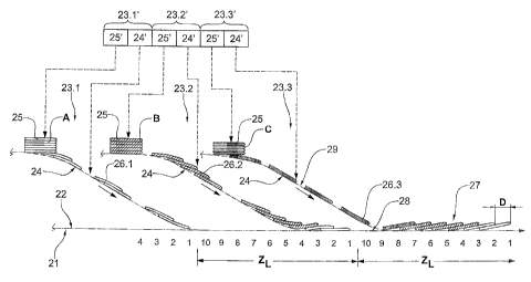
Figure 1 shows in a very schematic manner a first, exemplary embodiment of the
method according to the invention. The device for carrying out the method
comprises
a main conveyor 21 with a conveying surface 22 (schematically depicted as a
dot-
dash line) and three supply means 23.1, 23.2 and 23.3, wherein each one of the
supply means comprises an intermediate conveyor 24 (schematically illustrated
as a
dot-dash line) and an article source 25 (schematically depicted as a stack).
Supply
means 23.1 deposits a type A of flat articles on the conveying surface 22,
supply
means 23.2 a type B and supply means 23.3 a type C.
The articles of the three article types A, B and C of Fig. 1 are shown by
different
hatchings, they are, however, all depicted as being of the same size. The
types of
articles which can be processed with the method according to the invention are
not,
however subject to such conditions, i.e. they may have very different
thicknesses and
formats or they may all be of the same size. It is equally no prerequisite for
the
method according to the invention, that the scale spacings D in the stream to
be
established or in the imbricated formations 26.1, 26.2, 26.3 preformed on the
intermediate conveyors 24 are the same for all supply means, as is shown in
Fig. 1.
The stream to be established in the process as shown in Fig. 1 shall, for
example,
comprise uninterrupted imbricated stream sections 27 each comprising two
articles
of type A, four articles of type B and one article of type C. The preforrned
imbricated
CA 02466710 2004-05-07
_9_
35-106 CA
formations 26.1, 26.2, 26.3 in the intermediate conveyors 24 are to be
deposited
overlapping one another. Furthermore, gaps 28 are to be left between the
imbricated
stream sections 27, which gaps correspond to three deposited articles. A
deposition
cycle therefore has to comprise ten clock cycles (for depositing seven
articles and for
establishing the gap 28). The main conveyor 21 travels through a distance,
which
corresponds to the scale spacing D in each clock cycle. In Fig. l, clock
cycles and
deposition cycles ZL are indicated as conveying distances. The intermediate
conveyors 24, when active, travel in each clock cycle a distance, which
corresponds
to the scale spacing of the imbricated formation to be preformed (in case of
Fig. 1
equal to D).
As already mentioned above, the main conveyor and the intermediate conveyors
of
the system shown in Fig. 1 are operated with the same speed. This, however, is
not a
necessity. It is possible without further ado to operate the intermediate
conveyors
with speeds being different from the main conveyor speed and being different
from
1 ~ one another and to correspondingly adjust the scale spacings in the
irnbricated
formations being made ready. It is also not a prerequisite for the method
according to
the invention, that in all imbricated formations deposited on the main
conveyor the
scale spacings are the same.
As already described further above, the article sources 25 and the
intermediate
conveyors 24 of the individual supply means 23.1, 23.2 and 23.3 advantageously
are
individually controlled, as is very schematically indicated in Fig. 1 with six
control
units and corresponding data lines (illustrated with broken lines). One pair
of control
units is assigned to each supply means and is correspondingly designated with
23.1',
23.2' and 23.3'. Each pair comprises a unit 25' for controlling the article
source and
a unit 24' controlling the intermediate conveyor. It goes without saying, that
the
control units do not have to be hardware units.
CA 02466710 2004-05-07
-10-
35-106 CA
If the imbricated formations being preformed on an intermediate conveyor are
not
distanced from one another, i.e., if the intermediate conveyor carries a
continuous
imbricated stream, of which per activity phase one section is to be deposited,
then it
is not necessary, that the article source and the intermediate; conveyor are
controlled
independently of one another.
Figure 2 is a control diagram for the method according to the invention, as
essentially illustrated in Fig 1. On the abscissa (time axis), the clock
cycles are
consecutively numbered and the deposition cycles Zz~ are indicated as time
units. On
the ordinate the statuses (a = active, p = passive) of the individual
components
(unbroken line: main conveyor or intermediate conveyor respectively; broken
line:
article source).
The main conveyor 21 is continuously active. On the intermediate conveyor 24
belonging to supply means 23.1, imbricated formations 26.1 containing two
articles
of type A each and being distance from one another are preformed, i.e. the
intermediate conveyor 24 and the article source 25 are active for depositing
and
preparing an imbricated formation 26.1 in the clock cycles 1 and 2 of each
deposition
cycle ZT. The intermediate conveyor alone is active in a number of following
clock
cycles (according to Fig l: clock cycles 3 and 4), in which a spacing 29
between
preformed imbricated formations 26.1 is established. In the remaining clock
cycles of
each cycle ZT the intermediate conveyor 24 and the article source 25 of the
supply
means 23.1 are passive.
In the same manner, the intermediate conveyor and article source belonging to
supply means 23.2 are active in the clock cycles 3 to 6 (depositing and
preforming)
and the intermediate conveyor is active in the clock cycles 7 and 8 (spacing
29). In
the remaining clock cycles intermediate conveyor and article source are both
passive.
CA 02466710 2004-05-07
-11-
35-106 CA
The intermediate conveyor and the article source belonging to supply means
23.3 are
active in the clock cycle 7 (depositing and preforming), only the intermediate
conveyor is active in the clock cycles 8 and 9 (spacing 29), both are passive
in the
remaining clock cycles
Synchronisation of depositing and preforming is to be adapted to the length of
the
intermediate conveyor, that is, to the number of imbricated formations which
can be
fitted on the intermediate conveyor. In Fig. 2, depositing and pre.forming
(active
phase of the intermediate conveyor and of the article source) commence
simultaneously for all supply means. This is not the case according to Fig. I,
where
the same lengths of the three intermediate conveyors and the same spacings 29
of
imbricated formations on all intermediate conveyors but different lengths of
the
imbricated formations 26.1, 26.2, 26.3 render differing phase shifts between
depositing and preforming necessary. The spacings 29 (in clock cycles) between
preformed imbricated formations may also be different for the different
intermediate
conveyors, this in particular when processing types of articles having a
different
length in conveying direction. It is also possible to maintain the stroke of
all
intermediate conveyors to be the same and constant, independent of the number
of
articles to be deposited in a deposition step in such a manner, that the sum
of the
clock cycles, which are available for depositing and for spacing is constant.
Furthermore, the scale spacings D in the imbricated formations 26.1, 26.2, and
26.3
of the individual intermediate conveyors 23.1, 23.2 and 23.3 and
correspondingly in
the imbricated stream established on the main conveyor 21 may be different.
From Fig. 2 it is apparent, that for establishing individually differently
composed
imbricated stream sections 27 on the main conveyor, i.e. of imbricated stream
sections comprising different article numbers of article types A, B and C,
either the
CA 02466710 2004-05-07
-12-
35-lU6 CA
cycles ZT or the gaps 28 have to have different lengths. The individual supply
means
23.1, 23.2, 23.3 and the intermediate conveyor 24 and the article source 25 of
each
supply means have to be controlled in correspondence with the number of
articles to
be deposited or to be preformed in each cycle.
Figure 3 is a further schematic control diagram for a device as shown in Fig.
1.
According to this control diagram it is significantly more simple to produce
on the
main conveyor 21, individually differently composed and differently long
imbricated
stream sections 27 or groups of imbricated stream sections respectively.
In accordance with this control diagram, there are clock cycles reserved for
deposition by every supply means 23.1, 23.2 and 23.3 (e.g., 23.1: clock cycles
1 to 4;
23.2: clock cycles 5 to 10; 23.3: clock cycles I I to L3; gap 28: clock cycles
14 to 16),
wherein the number of these reserved clock cycles corresponds to a greatest
possible
imbricated formation 2b to be deposited (e.g., 23.1: max. four articles; 23.2:
max. six
articles; 23.3; 23.3: max. three articles). If these maximum formations are
deposited
by all supply means, the imbricated stream sections 27 deposited on the main
conveyor form an uninterrupted imbricated stream sectio. If smaller imbricated
formations are deposited, there are gaps between the deposited imbricated
formations.
For the cycle ZT illustrated in Fig. 3, for example, the following is
applicable: supply
means 23.1: deposit max. four articles, preform three articles; supply means
23.2:
deposit max, six articles, preform six articles; supply means 23.3: deposit
max. three
articles, preform one article. The number of articles being deposited in the
cycle
depends on the imbricated formations which have been preformed in
corresponding
earlier cycles. Whether the preformed imbricated formations in the cycle
represented
are deposited in the next or in a Later cycle, is dependent on the length of
the different
CA 02466710 2004-05-07
_l;_
35-106 CA
intermediate conveyors or on the number of separate imbricated formations
fitting on
the intermediate conveyor respectively.
Figures 4 and 5 illustrate two examples of supply means 23 for the device
according
to the invention, each comprising an article source 2~ and an intermediate
conveyor
24. In Fig. 4, the article source 25 is a stack with articles being removed
from its
bottom side (as is the case in a sheet feeder), and the intermediate conveyor
is a per
se known, twisted conveyor loop, which, for example, is implemented with an
inner
stationary track of freely rotating rollers and an outer driven circulating
belt pressed
against the rollers by spring force. The preformed imbricated formations are
advanced clamped between the rollers and the belt. A supply means with an
intermediate conveyor implemented as a twisted conveying loop is suitable in
particular for tight space conditions and is very suitable for manual article
supply,
wherein an operating person is easily capable of taking care of a plurality of
such
supply means.
The article source 25 in accordance with Fig. 5 is a sheet feeder arranged
above the
main conveyor 21 and the intermediate conveyor 24 is implemented as pair of
conveyor belts driven in opposite directions and running in an essentially
straight
line, wherein the conveyor belts are pressed against one another by spring
force and
the articles are advanced being clamped between them.
Figure 6 illustrates an installation for producing packages of printed
products,
wherein every package may comprise printed products of three different types
A, B,
and C. In the installation an article stream is created, in which the articles
are
conveyed in imbricated stream sections 27, wherein every imbricated stream
section
contains the articles to be included in one stack or package. This stream is
supplied
to a stacking device 30, in which every imbricated stream section 27 is made
into a
..,...... .,.,..:-. xn~_c.~s,. «.,~,wnz~.".,.-
..,~.~".z...,.~,y~yyyc~,.~..,wy~,..~:~.~~,pp~,~,.~~.~."..,._.,.",............._
..____.~__... ....._...._.. ...........___..._.".,.,-.,...:.~.."n:.,~.,.....,.-
>..,...,.._.......",.",..,~,~",.~,
CA 02466710 2004-05-07
- 14-
35-106 CA
stack 31. The stacks 31 are then conveyed to a strapping device 32, in which
every
stack is strapped to from a package 33.
For establishing the stream, a main conveyor 21 and three supply means 23.1,
23.2
and 23.3 are in use, as already described in association with Fig. 1. These
are, for
example, controlled in accordance with Fig. 2. The supply means comprise each
an
article source (source of printed products) and an intermediate conveyor 24
according to Fig. 4 (not depicted in Fig. 6). The main conveyor 21 is
implemented as
a conveyor belt.
If the printed product types A, B and C comprise different formats, then it is
advantageous, as is depicted in Fig. 6, to assign to the supply means 23.1
arranged
furthest away from the stacking device 30, the largest printed product type
and to
assign to the supply means 23.3 arranged closest to the stacking device 30,
the
smallest printed product type. In this manner it becomes possible to establish
stable
stacks despite the different formats. With the arrangement according to Fig.
6, mixed
1 ~ stacks or packages containing besides printed products, for example, CDs
in
corresponding envelopes or other flat articles can be produced without any
problems.
From Fig. 6 it is also apparent, how easily the arrangement can be expanded by
adding further supply means.
Instead of providing a stacking device as illustrated in Fig. 6, the
imbricated stream
sections being conveyed on the main conveyor downstream of the last supply
means
23.3, can also be pushed on top of one another to form a stack during
conveyance.
For this purpose it is necessary, that the imbricated formations deposited by
the
individual supply means overlap one another (uninterrupted imbricated stream
section). A device designed for such stacking by pushing, is described, for
example,
in the publication DE-19533086 (or US-5733099).