Note: Descriptions are shown in the official language in which they were submitted.
CA 02466727 2004-05-19
WO 03/045133 PCT/SE02/00800
VACUUM SYSTEM COMMUNICATION
TECHNICAL FIELD
The present invention relates to controlling vacuum system
parameters in an automatic milking system. More particularly,
the invention relates to increased energy efficiency, as well
as increased reliability and more stable operation of a vacuum
system in an automatic milking system.
BACKGROUND OF THE INVENTION
A milking system is one of the most important components on a
dairy farm, for it is used more hours per year than any other
type of equipment. A key.component of a milking system is a
vacuum pump, which is used to remove air from the milking
system pipelines to create a partial vacuum. In a conventional
vacuum milking system, the vacuum pump runs at full speed all
the time, regardless of air demands. A vacuum regulator is
generally used to regulate the desired vacuum level by
admitting external air, as required, when the vacuum level
reaches a predetermined setting. The nominal vacuum levels
normally used for milking usually are selected to be in the
range from 40 to 50 kPa, but vacuum fluctuations can occur in
the system, as when a milking unit falls off the cow being
milked, or when the system develops an air leak. It is
essential that such fluctuations be limited to enable the
vacuum system to meet ASAE standards as well as other
standards. This is difficult to achieve, because such
incidents can cause airflow in the system to increase over
what is needed when the system is operating properly. To
compensate for such variations, the size of the vacuum pump is
selected to provide the desired vacuum level even when there
is a large amount of leakage, and the vacuum regulator
compensates vacuum fluctuations. Thus, for example, a vacuum
pump operates at a constant rate sufficient to maintain a
1
CA 02466727 2004-05-19
WO 03/045133 PCT/SE02/00800
predetermined vacuum level in a reservoir even under leakage
conditions, and a vacuum regulator connected to the reservoir
admits air as required to control the vacuum level during
normal operating conditions.
In such prior systems, if there is an increase in airflow
through the milking system, airflow through the vacuum
regulator is reduced so that the reservoir maintains the
required vacuum level in the milking line. Ideally, in such
systems, increases in the airflow in the milking system should
result in decreases in the airflow through the regulator, and
these should be about equal to cancel each other and to
maintain vacuum equilibrium in the reservoir. The problem with
this arrangement is that only a small portion of the vacuum
pump capacity is actually needed for milking, with majority of
the airflow passing through the regulator. In such
arrangements, the capacity of the vacuum pump always exceeds
the capacity needed to milk cows or to wash the milking
system, and the pump always runs at full speed and full load,
regardless of the actual need for vacuum.
Particularly, for modern automatic robotic milking systems,
where animals may visit the automatic milking machine at will,
the vacuum need may vary substantially over time, not only due
to leakage or other incidents, but also for the reason that
animals arrive at irregular intervals to the automatic milking
system.
A recent improvement over the foregoing conventional system is
described in U.S. Pat. No. 5,284,180, which discloses a system
for varying the speed of a vacuum pump to maintain the
required, vacuum level and stability in the system. In this
patent, a vacuum level controlling system utilizes a two-level
controller combined with an adjustable speed motor drive for
the pump.
2
CA 02466727 2004-05-19
WO 03/045133 PCT/SE02/00800
US 5,960,763 describe a system and method, which supplies
different vacuum levels depending on if the milking machine,
is in washing or milking mode. It is possible to select which
mode should be used at any time.
None of the above patents concerns the specific problems
associated with robotic milking systems, e.g. animals arriving
at irregular intervals to be milked.
A further problem is how to achieve better surveillance and
monitoring of the workings of the vacuum pump system.
There is, therefore, a need for an automatic control system,
for a vacuum pump in a milking system to provide an improved
vacuum control system, for reducing electrical energy
consumption, which will meet the needs of modern dairy farms.
SUMMARY OF THE INVENTION
It is a main object of the present invention to provide such
apparatus and method that reduces the electrical energy
consumed in an automatic milking system.
It is in this respect a particular object of the invention to
provide such apparatus and method that adapts the supplied
vacuum level to the immediate or near immediate vacuum need as
required by an automatic milking system.
It is still a further object of the invention to provide such
apparatus and method that enables a milking system controller
to command a vacuum system controller to set a specific vacuum
level.
It is another object of the invention to provide such an
apparatus and method that enables communication between a
vacuum pump arrangement and an automatic milking system
controller.
3
CA 02466727 2004-05-19
WO 03/045133 PCT/SE02/00800
These objects among others are, according to a first aspect of
the present invention, attained by an automatic milking system
comprising a vacuum pump arrangement. The automatic milking
system comprises a milking system controller arranged to
control milking system parameters and the vacuum pump
arrangement comprises a vacuum system controller for
controlling vacuum system parameters. The system further
comprises communication means coupled to the vacuum system
controller and to the milking system controller for
establishing communication between the vacuum system
controller and the milking system controller, and the milking
system controller comprises signal transmitting means (108;
514) for transmitting a message to said vacuum system
controller. The vacuum system controller comprises signal
receiving means (107; 513) for receiving said message from
said milking system controller, and the vacuum system
controller is arranged to change at least one of said vacuum
system parameters depending on said received message.
The automatic milking system may further comprise, according
to a preferred embodiment of the invention, signal
transmitting means, arranged in the vacuum system controller
for sending a message relating to at least one of the vacuum
parameters to the milking system controller, and the milking
system controller thus comprises signalling receiving means
(108; 514) for receiving said message.
These objects among others are attained, according to a second
aspect of the present invention, by a method for controlling
and monitoring a vacuum pump arrangement for supplying vacuum
to an automatic milking system, wherein the vacuum pump
arrangement comprises a vacuum system controller for
controlling vacuum system parameters relating to said vacuum
system and the automatic milking system comprises a milking
4
CA 02466727 2004-05-19
WO 03/045133 PCT/SE02/00800
system controller for controlling milking system parameters
relating to said automatic milking system. The method
comprises the steps of sending a message from the milking
system controller to the vacuum system controller, using a
communications means coupling the milking system controller to
the vacuum system controller, and changing, by means of the
vacuum system controller, at least one of the vacuum system
parameters, in dependence of said received message.
The method may further comprise, according to a preferred
embodiment of the invention the further steps of detecting a
vacuum system parameter by the vacuum system controller, and
sending the detected vacuum system parameter from the vacuum
system controller to the milking system controller, using said
communications means coupling said milking system controller
to said vacuum system controller.
Thereby, the milking system controller may read milking system
parameters, such as measured vacuum level in the milking
system, for instance, in a milking conduit or at an end unit,
and compare these with vacuum system parameters, such as a
vacuum level as reported by the vacuum system controller. If
the two measured vacuum levels, i.e. the milking system vacuum
level and the vacuum system vacuum level, deviate more than a
value, a fault may be reported, or the milking system
controller may command the vacuum system controller to
increase the supplied vacuum, whereby the vacuum system
controller typically will increase the speed of a vacuum pump
motor by means of a VSD (Variable Speed Drive).
The milking system parameters may also include such parameters
that relate to the current status of the milking system, or
parts of the milking system. Such parameters may for instance
be the identification of an animal to be milked, if a specific
gate is opened or closed (which could indicate that one or
CA 02466727 2004-05-19
WO 03/045133 PCT/SE02/00800
several animals are soon going to be milked), the
identification of an animal to be milked, for which a specific
procedure will be applied which requires an increased vacuum
level or which procedure increases the air inlet, such as a
more demanding washing procedure. Other parameters could be
that no vacuum is needed for the moment in which case the
vacuum controller typically would turn of the vacuum pump or
set the vacuum pump to maintain a stand-by vacuum level, which
is lower than the vacuum levels required for teat cleaning and
milking and thus substantially less energy requiring.
An advantage of the present invention is that energy savings
is obtained in an automatic milking system.
A further advantage is that better surveillance is obtained
over the function of the vacuum pump system.
Yet a further advantage is that control is achieved over the
vacuum pump system by the automatic milking system.
A further advantage of the present invention is that an even
vacuum level with few fluctuations can be achieved in the
milking system when the vacuum system controller is instructed
to raise the vacuum before the need for higher vacuum levels
arise.
Further characteristics of the invention and advantages
thereof will be evident from the following detailed
description of embodiments of the invention.
BRIEF DESCRIPTION OF THE DRAWINGS
The present invention will become more fully understood from
the detailed description of embodiments of the present
invention given herein below and the accompanying Figs. 1 to
5, which are given by way of illustration only, and thus are
not limitative of the present invention.
6
CA 02466727 2004-05-19
WO 03/045133 PCT/SE02/00800
Figure 1 shows a schematic drawing of an automatic milking
system and a vacuum pump system according to a preferred
embodiment of the invention.
Figures 2a and 2b show two different views in more detail of
the automatic milking system in figure 1 comprising an
automatic robotic milking system according to a preferred
embodiment of the invention.
'Figure 3 shows schematic flow diagram according to a preferred
embodiment of the invention.
Figure 4 shows another schematic flow diagram according to a
preferred embodiment of the invention.
Figure 5 shows a milking pit comprising four milking points
according to a preferred embodiment of the invention.
PREFERRED EMBODIMENTS
In the following description, for purposes of explanation and
not limitation, specific details are set forth, such as
particular techniques and applications in order to provide a
thorough understanding of the present invention. However, it
will be apparent to one skilled in the art that the present
invention may be practiced in other embodiments, which depart
from these specific details. In other instances, detailed
descriptions of well-known methods and apparatuses are omitted
so as not to obscure the description of the present invention
with unnecessary details.
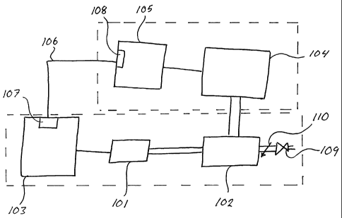
Figure 1 shows a schematic diagram of a device according to
the present invention. A vacuum pump arrangement 101 is
connected to a vacuum ballast or distribution tank 102. A
vacuum system controller 103 controls the vacuum pump
arrangement 101 including a VSD (Variable Speed Drive) (not
shown) controlling a motor (not shown). The ballast tank 102
7
CA 02466727 2004-05-19
WO 03/045133 PCT/SE02/00800
is in turn connected to an automatic milking system 104,
having a milking system controller 105.
The milking system controller 105 is a computer system
controlling the operation of the automatic milking system 104,
such as identifying an animal using a conventional
identification system (not shown), measuring the collected
milk and/or milk flow from an animal, initiating take-off of
teat cups when the milk flow has ceased etc.
For an automatic milking system comprising an automatic robot
additional milking system parameters have to be regarded such
as deciding if an identified animal is accepted for milking,
opening gates, initiating teat cup application etc.
The vacuum system controller 103 is connected to the milking
system controller 105 by means of a connection means 106. The
connection means 106 can be any of a multitude of different
message carrying media, such as Ethernet Lan, Wireless Lan or
even the Internet or as simple as ordinary copper wires. The
important aspect is that the vacuum system controller
comprises transceiver means 107 capable of sending and
receiving messages to a transceiver 108 in the milking system
controller thereby allowing communication between said vacuum
system controller and said milking system controller. The
communication, as such, is performed in a conventional manner
well known to one skilled in the art.
A regulation valve 109 leaks air into the milking system if
the vacuum levels are to high, thus keeping the vacuum level
below a maximum level. A shut-off valve 110 may be used to
disconnect the regulation valve 109, should so be desired,
e.g. during washing of the milking system.
Figures 2a and 2b show the automatic milking system 104 in
figure 1 in greater detail in a preferred embodiment employing
8
CA 02466727 2004-05-19
WO 03/045133 PCT/SE02/00800
a robotic milking machine. An ARMS (Automatic Robotic Milking
System) 200 is shown in figure 2a. A main vacuum supply line
201 is connected through a vacuum line (not shown) to vacuum
ballast tank 102. The ARMS further comprises a robotic arm 202
for connecting teat cups and a washing cup, commonly denoted
203, to the teats of an animal. The ARMS 200 further comprises
an inlet gate 204 and an outlet gate 205.
In figure 2b parts of the ARMS in figure 2a are shown in
greater detail. Four milk flow meters 206 measure the milk
flow from each teat individually and a fifth milk meter 207
measure the collected milk from all of the four teats
together. A receiver tank 208 collects the milk for later
transport to a milk tank by means of a milk pump 209. All the
devices shown, i.e. the robot arm 202, the teat cups and the
washing cup 203, the inlet gate 204, the outlet gate 205, the
milk flow meters 206, the milk meter 207, the receiver tank
208 and the milk pump 209, as well as many more features not
specifically mentioned but included in a conventional ARMS,
such as valves, compressed air, pistons etc, are controlled by
an ARMS controller 210.
Figure 3 shows a flow diagram of a preferred embodiment
according to the invention describing one of the processes of
the invention in an ARMS (automatic robotic milking system).
The milking system detects and identifies 301 an animal
wanting access to the ARMS. Normally, the sequence to be
followed for an animal to be milked is to first clean the
teats of the animal by means of a washing cup, applying the
milking cups, monitoring the milk flow from all and/or each of
the teats, removing the teat cups, disinfecting the teats and
finally washing the teat cups, milk lines and other equipment
used.
9
CA 02466727 2004-05-19
WO 03/045133 PCT/SE02/00800
If the animal is allowed for milking 302 the ARMS controller
105 sends a message 303 to the VSC (vacuum system controller)
103, commanding the VSC to set a particular vacuum level by
adjusting the speed, i.e. in revolutions per minute, of the
motor, by means of the VSD, to a teat cleaning value. By
increasing the speed of the motor driving the vacuum pump a
higher vacuum level will be achieved. However, when a certain
vacuum level, e.g. 50 kPa, has been reached the regulation
valve 109 in figure 1 will start to leak air so as to keep the
vacuum level from reaching to high levels.
During teat cleaning the leakage of air into the vacuum system
is larger than during, for instance milking, i.e. more vacuum
is needed and the speed of the vacuum pump motor is thus set
accordingly as described above. In this respect it would be
advantageous to send the message somewhat before the actual .
teat cleaning sequence is performed so that the vacuum system
is given time to adjust the vacuum level accordingly to avoid
vacuum level fluctuations.
In prior art systems the vacuum level would sink with
increased inflow of air. A sensor would notice the situation
and an order would be issued to increase the speed of the
vacuum pump motor to again achieve the correct vacuum level,
e.g. the milking vacuum level. However, during a period the
vacuum level will drop and may fluctuate before equilibrium is
achieved. This is undesirable.
Generally, the term "increased vacuum need" most often refer
to a situation with an increased influx of air and with
requirements to maintain constant vacuum. To balance the air
inlet the vacuum pump motor need to increase its speed to
displace to increased amount of air so as to maintain the
vacuum level.
CA 02466727 2004-05-19
WO 03/045133 PCT/SE02/00800
When ordering increased speed of the motor, a higher vacuum is
eventually built up, however this may take a short time
depending on the need for the motor to reach the correct
speed, time for vacuum build up etc. If the speed is increased
exactly at the same time as the need for increased vacuum
arises, that is for instance when a specific operation
allowing an increased inflow of air into the milk line, such
as teat cleaning, is to take place, the vacuum level will
fluctuate before an equilibrium is achieved. These
fluctuations are undesirable. However, if the order is given
to the motor beforehand, it will speed up to a speed known to
give an adequate vacuum level during a relevant operation, in
this case, a teat cleaning operation. Vacuum is gradually
built up in the vacuum ballast tank and eventually the
regulation valve 109 will let air into the tank to maintain
the vacuum level at an acceptable level as discussed above.
When the actual need for vacuum occurs, that is during teat
cleaning, the valve 109 will close, since the teat cleaning
causes increased inflow of air and the desired vacuum level is
maintained with minimal vacuum fluctuations and low energy
consumption since the vacuum pump can be set to work at a
higher speed only when a need for more vacuum arises.
It is also advantageous if the vacuum system sends a message
to the ARMS controller indicating that the correct vacuum
level has been achieved. The ARMS controller may then check to
see if the reported vacuum level corresponds to the vacuum
level as measured by the .ARMS. The process is then set into a
sleep mode waiting for a trigger 306 indicating that teat
cleaning has finished.
If the animal is not allowed into the ARMS, the ARMS
controller checks 304 if a predetermined time have passed
since the last animal was milked. If this is the case a
11
CA 02466727 2004-05-19
WO 03/045133 PCT/SE02/00800
message is sent 305 to the VSC to set the speed of the vacuum
system motor to maintain a stand-by vacuum level, which is
significantly lower than the normal milking vacuum level.
Thus, energy is saved as soon as the ARMS is not used for
milking. This check, if a predetermined time has passed since
the last milking, is also continuously performed when no
animals present themselves before the ARMS and a stand-by
vacuum level is set if the check is true.
It would be equally possible to completely turn-off the vacuum
pump, thus setting the vacuum level to atmospheric pressure.
This would save even more energy, however it is in some
milking systems advantageous to keep a minimum vacuum level in
the system to save sealing devices from fatigue, loosing their
sealing effect etc.
When the ARMS controller indicates, by the trigger 306, that
the teat cleaning sequence has ended or is soon to be ended,
and a milking sequence, comprising a teat cup application
phase and a milking phase, is about to start, a message is
sent 307 to the VSC commanding the VSC to set the speed of the
vacuum system motor to a teat cup application speed. In this
respect it would be advantageously to send the message
somewhat before the actual application of the teat cups is to
be performed so that the vacuum system can adjust the vacuum
level accordingly. During the teat cup application air inflow
is increased and the vacuum pump motor speed is set
accordingly. The process is then put to sleep waiting for a
trigger 308 indicating the end of teat cup application and the
start of the milking phase.
When the ARMS controller indicates, by the trigger 308, that
the teat cup application phase has ended or is soon to be
ended, a message is sent 309 to the VSC commanding the VSC to
set the speed of the vacuum system motor to a milking vacuum
12
CA 02466727 2004-05-19
WO 03/045133 PCT/SE02/00800
speed corresponding to a milking vacuum level. This milking
vacuum level can advantageously be individually set depending
on the present animal to be milked but is normally set to 45
kPa. The process is then put to sleep waiting for a trigger
310 indicating the end of the milking phase or the soon end
thereof.
When the ARMS controller indicates, by the trigger 310, that
the milking phase has ended or is soon to be ended, a message
is sent 311 to the VSC commanding the VSC to set the speed of
the vacuum system motor to a washing vacuum speed. During
washing of the teat cups, milk lines etc. it is normal that
substantially more air is let into the system than during the
milking of the animal. Thus it is advantageously to set the
speed of the motor of the vacuum pump to a higher value
somewhat before the actual washing starts as discussed above.
when the ARMS controller indicates, by the trigger 312, that
the washing phase has ended or is soon to be ended, a message
is sent 313 to the VSC commanding the VSC to set the speed of
the vacuum system motor to maintain a stand-by vacuum level.
This stand-by vacuum level corresponds to a significantly
lower speed of the vacuum system motor. This stand-by vacuum
level is suitable for the intermediate time when one animal
leaves the ARMS and the next is to be allowed into the ARMS,
or in wait for the next animal to arrive. Advantageously this
level is 20 kPa but may be less to save even more energy. The
process then continues at block 302.
By the arrangement described above, it is possible to adapt
the required vacuum levels, to the individual animal, to
achieve a better treatment of the animal, increase milk
production and, at the same time, save consumed energy, since
the vacuum pump is at all times made to work at the most
economical level. Also the vacuum level may be adapted to
13
CA 02466727 2004-05-19
WO 03/045133 PCT/SE02/00800
situations where there is no apparent immediate need for the
vacuum levels normally held during milking, such as when no
animal is due to be milked or when no animal presents itself
for milking, and thus the vacuum level may be lowered during
these periods, resulting in less consumption of electrical
energy, without any detrimental effects to the operation of
the automatic milking machine.
Figure 4 shows a process in the ARMS receiving a message from
the VSC. A message from the VSC is received 401 in the ARMS
controller and appropriate measures is taken. Depending of the
type of message a number of different actions may be
performed. If the message is an error message 402 indicating a
fault situation in the vacuum system, a fault is indicated 403
on a screen in the ARMS. Advantageously, an SMS (Short Message
Service) message may also be sent to a predefined mobile
number indicating the fault situation. If the message contains
a measured value for a vacuum system parameter 404 a check is
performed to see if the value is within allowed maximum and
minimum values 405. If the value is not within the acceptable
range a fault is indicated 406 on the ARMS screen and one or
more messages may be sent to the VSC ordering different
actions to be taken, such as shutting down the main vacuum
system and employing a back-up vacuum system if the reported
vacuum levels are below a specific value. If the value is
within the acceptable range, the value is indicated 407 on the
ARMS screen.
If the message is an acknowledge message 408, the ARMS is
updated 409 to reflect the safe receipt of the previously sent
message.
If the received message, at the ARMS controller, is a message
indicating 410 that the vacuum system requires service, an
indication of required service 411 is presented on the ARMS
14
CA 02466727 2004-05-19
WO 03/045133 PCT/SE02/00800
screen. Advantageously, the ARMS controller may send a message
to a service central, using SMS or TCP/IP, so that the service
central can arrange for the service of the vacuum system to
take place.
Figure 5 shows an automatic milking system with a milking pit
501, of which only a part is shown, a milking system
controller 502 and a vacuum system controller 503 according to
a preferred embodiment of the invention. The milking system
controller 501 and the vacuum system controller 503 are in
communication with each other through communications means 504
schematically depicted. The milking system controller 502
comprises signal transceiver means 514 and the vacuum system
controller comprises corresponding signal transceiver means
513. Said communication means 504 is arranged to send and
receive messages to and from the milking system controller 502
and the vacuum system controller 503. The milking system
controller 502 and the vacuum system controller 503 will
respond to received messages by performing different actions,
as discussed above.
Four milking points A, B, C and D are shown in figure 5. It is
clear that a general milking pit may contain more milking
points than four. Each milking point comprises a milking point
controller 505, 506, 507 and 508 for controlling various
milking parameters relating to each milking point, such as
measuring milk flow or amount, activating take off etc. Each
milking point controller 505, 506, 507 and 508 is connected to
the milking system controller 502 by communication means 509,
510, 511 and 512, respectively. Each milking point controller
may thus send information to the milking system controller
502, for instance regarding the present status (milking,
washing, take off, no operation etc.), fault indication,
amount of milk withdrawn, milk flow etc. Thus, the milking
CA 02466727 2004-05-19
WO 03/045133 PCT/SE02/00800
system controller 502 will have information relating to all
milking points 505, 506, 507 and 508 in the milking pit. The
milking system controller is more over connected to gates (not
shown) and other devices, such as a washing machine, for
monitoring their status, receiving information or sending
orders. For instance, the opening of a specific gate may
indicate that milking is to be commenced, or the milking
system controller may order the washing machine to start
washing.
According to this preferred embodiment of the invention, the
milking system controller 502 may receive information from
each milking point 505, 506, 507 and 508 that all milking
points are empty, that is, there are no animals present to be
milked. The milking system controller thus orders the vacuum
system controller to reduce the vacuum level to the stand-by
vacuum level to save energy. When a gate (not shown) is opened
to let in a new batch of animals to be milked, the milking
system controller 502 receives information regarding the
status of the gate and orders the vacuum system controller 503
to increase the vacuum level from the stand-by level to the
milking level.
When washing is to be started the milking system controller
502 orders the washing machine (not shown) to start washing
after ordering the vacuum system controller 503 to set the
vacuum motor speed to a washing vacuum speed. Alternatively
the washing machine may send a message to the milking system
controller before starting washing, in which case the milking
system controller 502 will respond with an order to the vacuum
system controller 503 to increase the vacuum motor speed.
If a milking point 505, 506, 507 or 508 reports low vacuum
levels to the milking system controller 502, alternatively if
the milking system controller 502 itself register low vacuum
16
CA 02466727 2004-05-19
WO 03/045133 PCT/SE02/00800
levels, it may order the vacuum system controller 503 to use a
second back-up vacuum pump and motor (not shown) and indicate
the fault on a suitable media.
It will be obvious that the invention may be varied in a
plurality of ways. Such variations are not to be regarded as a
departure from the scope of the invention. All such
modifications as would be obvious to one skilled in the art
are intended to be included within the scope of the appended
claims.
17