Note: Descriptions are shown in the official language in which they were submitted.
CA 02467567 2004-05-31
WO 03/067770 PCT/US03/03721
-1-
METHOD AND APPARATUS FOR TRANSMITTING INFORMATION ABOUT
A TARGET OBJECT BETWEEN A PRESCANNER AND A CT SCANNER
Field of the Invention
The present invention is directed to the field of X-ray detection systems.
Background of the Invention
There exists a need for improved systems and methods of screening baggage for
explosives, weapons, and other contraband. Some existing systems employ X-ray
scanners, computed tomography (CT) scanners, or other imaging devices to
detect
concealed objects. In some such systems, a CT scanner is preceded by an X-ray
scanner,
which performs a "prescanning" function to determine initial information on
the contents
of an article of baggage. Existing X-ray based systems provide differing
degrees of
sophistication in terms of their ability to analyze baggage based on the X-ray
data
obtained. Some, for example, balance the speed of the baggage screening with
the
accuracy and reliability with which contraband is detected. While the
prescanning
function discussed above may increase the accuracy and reliability with which
contraband is detected, there exists a need for improved systems and methods
of
screening baggage.
Summary of the Invention
One embodiment of the invention is directed to a method or apparatus for
analyzing an object in which a dual energy X-ray prescanner performs a.
prescan of the
object to determine prescan information about the object. Then, a CT scanner
performs a
CT scan on at least one plane of the object based on the prescan information.
If the CT
scan of the object includes or is in the vicinity of metal, then metal
artifact correction of a
reconstructed image from the CT scan may be performed using the prescan and CT
scan
information.
Another embodiment of the invention is directed to a method or apparatus for
analyzing an object in which a prescanner, which need not be a dual energy
prescanner,
CA 02467567 2004-05-31
WO 03/067770 PCT/US03/03721
-2-
performs a prescan of the object to determine prescan information. Then, a CT
scanner
performs a CT scan of the object to determine CT information. A processor
analyzes the
CT information and the prescan information to determine whether to update the
prescan
information based on the CT information.
While the description and claims herein recite use of a CT scanner, such term
is
intended to cover any device that measures at least density of an object
scanned by the
device.
Brief Description of the Drawings
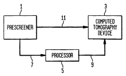
Figure 1 is a block diagram of an apparatus for transmitting information from
a
prescanner device to a CT scanner device according to one embodiment of the
invention;
Figure 2 is a block diagram of an apparatus for transmitting information from
a
CT scanner device to a prescanner device according to one embodiment of the
invention;
Figure 3 is a block diagram of an apparatus for transmitting information
between
a CT scanner device and a prescanner device according to one embodiment of the
invention;
Figure 4 is a flow diagram illustrating a method for transmitting information
between a CT scanner device and a prescanner device according to one
embodiment of
the invention;
Figure 5 is a diagram illustrating a grid for performing CT scans at
intervals;
Figure 6 is a diagram illustrating reference coordinates for a scanned item;
and
Figure 7 is a flow diagram illustrating a method for obtaining a CT image and
predicting and correcting metal artifacts of the CT image according to one
embodiment
of the invention.
Detailed Description
The present invention relates to a system or method in which a prescanner X-
ray
device and a downstream (of the prescanner) computed tomography (CT) device
scan an
object. The object may be located within a piece of baggage, a manufactured
product,
the human body, or some other item penetrable by X-rays. Information collected
on the
CA 02467567 2004-05-31
WO 03/067770 PCT/US03/03721
-3-
object may be transmitted from the prescanner to the CT scanner and/or from
the CT
scanner to the prescanner.
One embodiment of the present invention, illustrated in Figure l, is directed
to a
method and apparatus for transmitting information from a prescanner device 1
to a
downstream CT scanner device 3. This can be accomplished in any of numerous
ways,
and the present invention is not limited to any particular one of such ways.
In accordance with one illustrative embodiment, information from prescanner
device 1 is transmitted from prescanner device 1 to a processor 5 via a data
link 7. Data
link 7, and any other data link described herein, is not limited to any
particular type of
link and may be implemented using any suitable means for transmitting
information,
such as an Ethernet link.
Processor 5 may process the information transmitted from the prescanner
device,
and transmit the processed information, or a control signal with instructions
based on the
processed information, to CT scanner device 3 via a data link 9. Processor 5
may be
located external or internal to CT scanner device.
It should be appreciated that while Figure 1 illustrates both a direct
communication link, such as data link 11, and an indirect communication link
via a
processor, such as data links 7 and 9, both communications links are not
required. One
such communication link, or any other communication link that may be
envisioned by
one skilled in the art, may be implemented.
Prescanner device 1 may be any of numerous multiple energy X-ray devices. For
example, prescanner device 1 may be a single or multi-view dual energy line
scanning
X-ray device, a dual energy CT scanner device, or any other device capable of
measuring
effective atomic number characteristics of an object, the significance of
which will be
appreciated from the forthcoming discussion. U.S. Patent No. 5,838,758 (Krug),
which
is hereby incorporated by reference, teaches dual energy X-ray inspection
systems, any
of which may be employed as the prescanner device according to an embodiment
of the
invention.
CT scanner device 3 may be any of numerous devices for performing computed
tomography or, more generally, may be any device capable of measuring density
characteristics of an object. Prescanner device 1 and CT scanner device 3 may
be
CA 02467567 2004-05-31
WO 03/067770 PCT/US03/03721
-4-
implemented as separate units, as shown in Figure 1, or as a single unit
having both
prescanning and CT scanning functionalities.
The screening systems described herein may be used in a variety of
applications
to recognize and detect target objects of interest. Target objects may
include, but are not
limited to, concealed objects (e.g., explosive devices or other weapons)
inside a container
(e.g., baggage), defects (e.g., cracks, air bubbles, or impurities) in
articles of manufacture
(e.g., commercial products), and areas of interest (e.g., tumors or other
masses, including
masses located near bone, metal, or another high-density material from which
artifacts
may result) within the body. Thus, the invention described herein may be used,
for
example, in settings such as airports, manufacturing plants, and hospitals,
and other
settings in the travel, commercial, and medical industries.
Certain characteristics of target objects discussed above can be determined
mathematically based on the absorption of X-ray radiation by the object. The
absorption
of X-ray radiation by a material in an item is proportional to the degree of X-
ray
attenuation and is dependent on the energy of the X-ray radiation and the
following
material parameters: thickness, density, and atomic number. The relationship
between
these values can be described by Equation 1:
IX = Io expU(N~P)x~ (1)
where, Ix is the intensity of the X-ray radiation after passing through a
material, Io is the
intensity of the X-ray radiation before passing through a material, N/p is the
mass
attenuation coefficient; and x is obtained by multiplying the thickness of the
material by
its density. It should be appreciated that since X-ray absorption by a
material is
dependent on the thickness, density, and atomic number of the material,
absorption and
attenuation may be most accurately determined when all three parameters of a
material
are known. The scanning devices described herein can accurately determine the
thickness, density, and/or atomic number of an object, and these parameters
may be used
to determine whether an object is a target object.
In the embodiment of Figure 1, prescanner device 1 performs an initial scan of
an
item, and CT scanner device 3 then may perform a subsequent scan of one or
more areas
of interest within the item, which are determined based on the initial scan.
Prescanner
device 1 may "feedforward" information relating to possible target object
areas
CA 02467567 2004-05-31
WO 03/067770 PCT/US03/03721
-5-
determined during the initial prescan to the CT scanner device 3 so that CT
scanner
device 3 scans only those slices that are located in regions where target
objects may
exist.
This method reduces the number of slices necessary to be taken by the CT
scanner, including the number of slices taken through metal, to detect a
target object and
increases the accuracy with which target objects are detected. A CT scanner
device
employed alone to scan an item performs CT scans of planes (or "slices") of
the item and
provides information on the three dimensional spatial configurations of
objects therein.
V~Ihile this technique is useful in identifying target objects within the
scanned item, each
CT scan is time consuming and has a limited image quality. Numerous of these
time-
consuming scans are required to ensure no target area is missed. By employing
prescanner device 1 upstream of the CT scanner, according to one embodiment of
the
present invention, possible target objects and their two-dimensional locations
are
determined in a quick (relative to a CT scan) prescan. A significant advantage
lies in
reducing the number of slices, and thereby reducing the scan time, for an
item.
In addition to reducing the scan time of the CT scanner device, the feeding
forward of information from prescanner device 1 to CT scanner device 3 may
increase
the accuracy of the CT scan images. For example, as will be described in
greater detail
below, for those slices that are in the vicinity of metal, the fedforward
information can be
used to perform metal artifact correction, thereby increasing the accuracy of
any
reconstructed image from the CT scan and ability to detect target objects.
Another embodiment of the present invention, illustrated in Figure 2, is
directed
to a method or apparatus for transmitting information from CT scanner device 3
to
prescanner device 1. According to this embodiment, information relating to a
potential
target object scanned by CT scanner device 3 is transmitted ("fedback") to a
processor to
determine whether to update information collected by prescanner device 1
relating to the
potential target object. For example, information collected by the prescanner
device,
relating to the effective atomic number and mass of a potential target object,
may be
inaccurate for areas of the scan where the potential target object overlaps
with another
object or objects. A CT scan of a region including the potential target
object, by
obtaining density information through scans of slices in different
orientations, can
distinguish the potential target object from background objects, and thereby
determine
CA 02467567 2004-05-31
WO 03/067770 PCT/US03/03721
-6-
the precise boundaries of the target object. This fedback information is
analyzed by the
processor to determine whether to update and improve the accuracy of the
information
(e.g., effective atomic number and mass) collected by prescanner device 1.
According to one embodiment of the invention (Figure 2), the processor is
located internal to prescanner device 1, and information from CT scanner
device 3 is
transmitted to the processor in prescanner device 1. The information may be
transmitted
in any of numerous ways, and the present invention is not limited to any
particular one of
such ways. For example, information from CT scanner device 3 may be
transmitted
from CT scanner device 3 to a processor 5 via data link 11. Processor 5 may
process the
information transmitted from CT scanner device 3, and transmit the processed
information to prescanner device 1 via a data link 13. Alternatively,
information may be
transmitted directly from CT scanner device 3 to prescanner device 1 via a
data link 15.
According to another embodiment of the invention, the information from CT
scanner
device 3 is not transmitted to prescanner device 1, but rather is transmitted
to a processor
located external to prescanner device 1. For example, information may be
transmitted to
a processor located in CT scanner device 3 or to a processor in an external
computing
system.
Another embodiment of the present invention, illustrated in Figure 3, is
directed
to transmitting information from prescanner device 1 to CT scanner device 3,
referred to
as the "feedforward mode", and from CT scanner device 3 to prescanner device
1,
referred to as the "feedbackwards mode." This embodiment combines the
embodiments
of Figures 1 and 2, above. As discussed previously, in the feedforward mode,
information relating to a two-dimensional location of a potential.target
object is
transferred from prescanner device 1 to CT scanner device 3 (or a processor
coupled to
CT scanner 3) to determine locations for CT slices to be performed, thereby
reducing the
CT scan time. Further in the feedforward mode, information relating to the
effective
atomic number and mass of potential target objects is transferred from
prescanner device
1 to CT scanner device 3 (or a processor coupled to CT scanner 3) to increase
the
accuracy of the CT images, particularly for those slices that are in the
vicinity of metal.
In the feedback mode, density information collected by CT scanner device 3 is
transmitted to prescanner 1 (or a processor coupled to prescanner 1) to enable
the
CA 02467567 2004-05-31
WO 03/067770 PCT/US03/03721
_7-
prescanner to update and improve the accuracy of the effective atomic number
and
mass information collected by prescanner device 1.
In the embodiment of Figure 3, information from prescanner device 1 is
transmitted to CT scanner device 3 via data link 17, and information from CT
scanner
device 3 is transmitted to prescanner device 1 via a data link 19. Data link
17 and data
link 19 may be separate data paths or may be implemented as a single data
path, such
that information is transmitted for both of the data links via a single
medium. Further,
data link 17 and data link 19 may be direct links or may pass through another
device,
such as a processor. Data processing may occur in an external processor, or
may occur
internal to each of prescanner device 1 and CT scanner device 3. As discussed
above,
though prescanner device 1 and CT scanner device 3 are illustrated separately
in Figure
3, it is not necessary that each be implemented as a separate unit. Rather,
prescanner
device 1 and CT scanner device 3 may be implemented as a single unit having
both
prescanning and CT scanning functionalities.
Figure 4 is a flow diagram according to one embodiment in which information
may be transmitted from prescanner device 1 to CT scanner device 3 in the
feedforward
mode, and from CT scanner device 3 to prescanner device 1 in the feedbackwards
mode.
It should be appreciated that, as discussed above, the feedforward and
feedbackwards
modes need not be implemented in the same screening system and that each may
be
implemented independently in a separate system. The flow diagram of Figure 4
shows
both information (i.e., data) flow (in phantom lines) and process flow (in
solid lines).
Beginning with step 20, an item (e.g., an article of baggage) to be screened
is
loaded into a machine of the invention. In step 21, the item is scanned and
analyzed
using the prescanner device 1. The prescanner device 1 may be a line scanner,
such as
one of the VIS series offered by PerkinElmer Detection Systems, the assignee
herein.
The item is initially loaded into the prescanner device 1 for scanning. For
example, a
human operator may place the item on a conveyor which, with the aid of a
motion
controller, moves the item through prescanner device 1. In one embodiment,
prescanner
device 1 has at least two X-ray sources for generating X-ray beams and may
have one or
more X-ray detectors for receiving X-ray beams. The X-ray image resulting from
the
scan consists of a two-dimensional array of pixels representing a view of the
three-
dimensional item from one angle. A processor, either internal or external to
prescanner
CA 02467567 2004-05-31
WO 03/067770 PCT/US03/03721
_g-
device 1, calculates the attenuation of the generated X-rays penetrating the
item for each
pixel. According to one embodiment of the invention, alternate pulses of high
energy X-
rays (e.g., 150 kV) and low energy X-rays (e.g., 75 kV) are respectively
generated by
dual X-ray sources, and the processor calculates the attenuation for each
pixel of the
image resulting from the respective high energy and low energy beams.
In a step 23, a table (Table A) is generated containing atomic number and mass
characteristics for each object. Table A may be stored electronically by a
memory (not
shown) coupled to a processor. Both the processor and the memory may be either
internal or external to prescanner device 1. An object may be defined as any
region
having similar atomic number and mass characteristics. The calculated
attenuation of the
high energy and low energy beam pulses for each pixel of the scanned item are
used to
determine the effective atomic number of all objects. To derive the effective
atomic
number of each object based on the attenuation, the attenuation of X-rays at
each
different energy level is analyzed. One method for doing so is described in
LJ.S. Patent
5,838,758 (Krug), incorporated by reference herein. It is known that materials
with a
high effective atomic number (e.g., metals) absorb low energy X-ray radiation
more
strongly, whereas materials with a low effective atomic number (e.g., organic
materials)
absorb high energy X-ray radiation more strongly. Thus, the effective atomic
number of
each object may be determined by analyzing the attenuation of low and high
energy X-
rays by each pixel. To determine the effective atomic number for a particular
object, all
pixels within the object are compared to pixels surrounding the object and a
histogram is
created, where the mode (peak of the histogram) represents the effective
atomic number.
In addition to effective atomic number information, Table A may also contain
mass information for each object. The mass for each pixel may also be
determined based
on the X-ray attenuation of both the high and low energy X-rays. The
relationship
between X-ray attenuation and material mass (i.e., thickness) is logarithmic;
X-ray
radiation decreases logarithmically as the material thickness increases. Thus,
mass may
be estimated by analyzing the attenuation of X-rays of all energies by
materials within an
item. To determine the mass for a particular object, mass values for all
pixels within an
object are added.
In an embodiment, Table A also contains confidence values for the effective
atomic number and mass values for each object. Confidence values for the
effective
CA 02467567 2004-05-31
WO 03/067770 PCT/US03/03721
-9-
atomic number and mass values represent a probability or range of
probabilities that the
atomic number and mass data are correct. To determine a confidence level for
the
effective atomic number value or mass value of a particular object, a feature
vector
denoting properties such as compactness, connectiveness, gradients, histogram
spread
and other features may be used.
Numerous known procedures are available for determining the confidence level.
One such procedure uses machine vision technology for object classification.
Machine
vision technology includes: (1) segmenting a group of picture elements from
their
background, (2) describing that group of picture elements by a set of
features, and (3)
using the resulting feature vector to classify the picture elements.
One software tool available for such object classification is Image Process
and
Analysis Software offered by Data Translation, Inc. as SPO550. Other software
packages
that provide similar tools for algorithm development include: Checkpoint~ by
Cognex
Corporation of Natick, MA, Frameworks by DVT of Woodcliff Lake, NJ, and the
Powervision~ family of products of RV SI of Canton, MA. The invention need not
be
limited to the features found in the exemplary software packages mentioned.
There are
numerous other approaches as described, for examples, in the following
textbooks:
1. Machine Vision: Theory, Algorithms, Practicalities (Signal Processing and
its
Applications Series), by E. R. Davies;
2. Computer Vision and Image Processing: A Practical Approach Using CVIPTools
(BI~/CD-ROM), by Scott E. Umbaugh;
3. Algorithms for Image Processing and Computer Vision, by James R. Parker;
and
4. Feature Extraction in Computer Vision and Image Processing, by Mark Nixon
and
Alberto Aguado.
A target object, such as an explosive, has a typical effective atomic number
and
mass value. Further, for a particular range of atomic number values, a
particular range of
mass values will be characteristic of a target object. Thus, it is useful to
consider both
atomic number and mass values in determining whether a target object is
present.
In a step 25, a list of objects warranting further study (i.e., objects of
interest),
including the locations for the objects, is generated. The atomic number
characteristics
of Table A can be used to differentiate potential target objects from the
background,
since different objects will generally have different effective atomic
numbers. A
CA 02467567 2004-05-31
WO 03/067770 PCT/US03/03721
-10-
potential target object may comprise a collection of pixels in close proximity
having
atomic number values that fall within a certain range. For example, a weapon
or
explosive may comprise a collection of pixels having high effective atomic
number
values that fall within a particular range. Thus, it is possible to determine
two-
dimensional coordinates (e.g., xl-x2, zl-z2 in Figure 6) of a potential target
object based
on effective atomic number and mass information.
While the list of objects warranting further study and two-dimensional
coordinates associated with each object may be generated automatically, it is
also
possible that a human operator may manually determine the information. For
example,
an operator may view an X-ray image to determine objects of interest and their
respective locations in two dimensions. Thus, the prescan analysis may be
performed
automatically or manually, and the invention is not limited to either method
of analysis.
~nce a location of an object of interest, or a region thereof, has been
determined,
a CT scan of the object or region of interest may be performed. Locations of
slices (i.e.,
two-dimensional planes) in the item to be scanned are chosen to coincide with
a potential
target object. Some target objects, such as explosives, are typically found
near metal
objects (e.g., wires, batteries). Metal, due in part to its high density, may
cause artifacts
in an image in the region surrounding the metal. Thus, if a potential target
object is
located near metal, it is preferable to choose a slice that includes the
target object, but
that is not in the vicinity of the metal. However, if a slice near metal is
chosen,
according to one aspect of the invention, a metal artifact correction is
performed to
correct for the image artifacts, as will be described in step 35.
If, after step 25, there are no objects warranting further study, a decision
may be
made as to an appropriate course of action, based on the prescan information
(Figure 4,
step 27). For example, an operator of an X-ray system in an airport may decide
to return
the baggage to the passenger, search the baggage by hand, or call the bomb
squad.
Alternatively, an algorithm may be used to automatically determine an
appropriate
course of action. If, in step 29, there are objects warranting further study,
the item (e.g.,
baggage) is transferred to the CT scanner device, for example via the
conveyor. If there
are no objects warranting further study, the item may or may not be
transferred to the CT
scanner device. According to one aspect of the invention, the item may be
transferred to
CA 02467567 2004-05-31
WO 03/067770 PCT/US03/03721
-11-
the CT scanner device when no objects warranting further study have been
detected so
that undetected objects (e.g., sheet explosives) may be screened for.
In step 3 l, CT images are generated for the item cross-sections identified in
step
25, if any. To form a CT image of a cross-section (i.e., slice) of an item, a
finely
collimated beam of radiation is passed through the item in the desired slice
plane, and the
attenuation is measured. The process is repeated and a set of projections is
acquired as
the X-ray beam is passed through the object at different angles. A
reconstructed image
of the two-dimensional distribution of the linear attenuation coefficient,
~(x,y), may be
obtained from these projections. If the projections could be acquired with an
infinitely
narrow X-ray beam, and the angular increment at which the X-ray beam is passed
was
negligible, the result would be a continuous set of projections. Displayed as
a two-
dimensional function, the continuous set of projections is referred to as the
sinogram.
An image may be reconstructed from the sinogram by implementing any of a
number of
well-known reconstruction techniques including, but not limited to, back
projection,
iteration, Fourier transform, and filtered back projection.
As discussed above, a CT image of a slice results in a two-dimensional image
of
a cross-sectional plane of the scanned item. The image consists of an array of
pixels
(e.g., 900 pixels x 512 pixels). According to one illustrative embodiment
shown in
Figure 5, CT scanner device 3 performs scans at locations along a grid 61,
such that
slices are imaged at predetermined intervals 63a-c along the length of the
item. For
example, an article of baggage may be imaged every distance x along its
length. In
Figure 5, a first slice 65 is imaged at zl cm, a second slice 67 is imaged z2
cm = (zl + x)
cm, and a third slice 69 is imaged at z3 cm = (zt + 2x) cm. Performing scans
according to
a grid pattern ensures that potential target objects that may not have been
identified as
warranting further investigation in step 25 are imaged. For example, sheet
explosives
may evade identification by the prescanner device because they are thin in
profile and
minimally attenuate X-rays. The CT scanner, on the other hand, may image a
number of
planes transecting the sheet explosive, and thus may more readily detect the
sheet
explosive. Preferably, the imaging points on the grid, discussed above,
coincide with the
objects warranting further study identified in step 25. For example, the first
and third
slices in Figure 5 intersect objects 7la,b. If not all objects of interest are
accommodated
CA 02467567 2004-05-31
WO 03/067770 PCT/US03/03721
-12-
by the grid, additional slices may be taken. Further, the grid is preferably
positioned to
avoid taking slices of metal objects, for the reasons discussed previously.
In step 33, it is determined whether any imaged object of interest is in the
vicinity
of a metal object. Additionally, it may be determined whether the image of the
object of
interest is likely to be distorted by metal artifacts caused by the metal
object. For
example, although a metal object is in close proximity to the object of
interest, it may be
determined that the size of the metal object relative to the object of
interest renders it
unlikely that the metal object will have a significant negative effect on the
image of the
object of interest (e.g., if the metal object is much smaller than the object
of interest). If
a potential target object is in the vicinity of a metal object, such that the
image of the
object is likely to be distorted by metal artifacts, a metal artifact
correction is performed
on the slice containing the metal artifacts, according to one aspect
(feedforward mode) of
the invention described herein.
If it is determined in step 33 that a potential target object is in the
vicinity of a
metal object, information fed forward from the prescanner device is used to
predict the
type and shape of metal responsible for the metal artifacts in step 35. In
particular, the
mass information and effective atomic number information from Table A are used
to
identify the metal type and perform a metal artifact correction specific to
the type and
shape of the metal. The metal artifact correction algorithm is described in
detail below in
connection with Figure 7.
In step 37, the scanned CT images are analyzed. According to one embodiment,
the density, area, and three-dimensional coordinates are determined for each
target
object, for example using image processing algorithms (e.g., region growing).
The area
of each target object is specified by a range of two-dimensional (e.g., xl-xz,
y-ya in
Figure 6) coordinates that delimit a region where the density of each pixel
falls within a
certain range. Further, a confidence level is determined for the density and
area values
associated with each pixel. Each confidence level represents a probability
that the
density or area data corresponding to that pixel is correct.
In step 39, a table (Table B) is generated containing the density, area, and
three-
dimensional coordinates for each target object, and a confidence level for
each
characteristic of each target object. Table B may be stored electronically by
a memory
(not shown) coupled to a processor and may, along with or separate from the
processor,
CA 02467567 2004-05-31
WO 03/067770 PCT/US03/03721
-13-
be either internal or external to CT scanner device 3. The three-dimensional
coordinates
for each target object are transmitted ("fed back") to prescanner device 1 in
step 41.
According to one aspect (feedback mode) of the invention, this information
from Table
B may be used to augment Table A. The processor, coupled to the memory that
stores
Table A, considers the fedback information and the information in Table A in
determining whether to update any of the information in Table A.
Since prescanner device 1 images the item from only one view, the prescanner
device may not be able to discern whether an identified object is a single
object or a
plurality of objects, as objects that overlap when imaged from a particular
perspective
may appear as a single merged object. Ifthe prescanner device cannot
differentiate a
plurality of overlapping objects, it may determine a mass value for an object
that is
actually the mass values of two or more objects combined. The three-
dimensional
coordinate information provided in Table B can be used to differentiate
objects, and
thereby correct erroneous effective atomic number values and mass values of
Table A. If
the mass of an object changes, the object may no longer be of interest or,
conversely,
may become interesting. For example, if an original mass determination is
based on two
merged non-target objects, the mass value will be erroneously high, and may
fall within
the range corresponding to a target object. When the two merged objects are
differentiated and their masses are determined separately, the individual
objects may no
longer be of interest if the mass value falls below a minimum mass associated
with
potential target obj ects.
In sum, the information fedback from Table B by the CT scanner device allows
for more accurate determinations of the effective atomic number and mass of
each
object, as listed in Table A, by the prescanner device. Hence, superior
detection by the
prescanner device and a lower false alarm rate may be achieved by feeding back
information from the CT scanner device to the prescanner device. It should be
appreciated that multiple feedforward/feedbackwards loops are possible,
whereby
information generated by the prescanner device 1 and CT scanner device 3 is
alternately
transmitted between the two devices. It should be appreciated that the
information from
Table B need not be transmitted to the prescanner device. Rather, the CT
scanner device
or an external computer may implement an algorithm, similar to that which may
be
implemented by the prescanner, to augment Table A based on the Table B
information.
CA 02467567 2004-05-31
WO 03/067770 PCT/US03/03721
-I4-
In step 27, a decision is made based on the information in Tables A and B as
to
an appropriate course of action. As discussed above, possible actions include
returning
the baggage to the passenger, searching the baggage by hand, or calling the
bomb squad.
An algorithm may be used to synthesize the information of the two tables to
determine
an appropriate action. For each potential target object, the algorithm may
consider the
effective atomic number, density, and associated confidence levels for each,
as well as
the thickness of the potential target object and the proximity of the
potential target object
to metal. Based on the information, a likelihood is determined that an
identified object is
a target object. The likelihood is derived from a histogram representing, for
example, the
probability that an object having a given effective atomic number, density,
thickness,
mass, and proximity to metal is a target object, and may be represented as a
probability
that the object is a target object or as an absolute indication that the
object is/is not a
target object. It should be appreciated that any of the automated decisions or
actions
described above may alternatively be performed by a human operator.
Figure 7 illustrates by flow diagram a method for obtaining a CT image and
predicting and correcting metal artifacts of the CT image, most steps of
which, as
illustrated, correspond to step 35 described above in connection with Figure
4. Like
Figure 4, the flow diagram of Figure 7 shows both information (i.e., data)
flow (in
phantom lines) and process flow (in solid lines).
In step 43, a CT image is generated. Uncorrected CT images may contain metal
artifacts when a scan is performed within a certain proximity to metal, which
may result
in inaccuracies. For example, beam hardening artifacts cause inaccuracies in
the
estimation of attenuation coefficients for pixels associated with x-rays that
traverse
highly attenuating structures. Streaky shadows or star patterns of streaks may
result near
high density objects in regions of pixels where essentially no attenuation
information
exists. Scatter artifacts may result from the dispersion of X-ray photons by
the atoms
within the item, and may cause noise in the CT image.
In step 45, the image is clipped so that the image contains only the metal
that
accounts for the artifacts of the image. The region to be clipped is
identified by
considering the effective atomic number information of Table A. Each pixel in
the
image of the metal will have an effective atomic number that falls within a
range
CA 02467567 2004-05-31
WO 03/067770 PCT/US03/03721
-15-
corresponding to the effective atomic number of the metal. The clipped image
contains
only the image of the metal, and does not contain the object of interest or
artifacts.
The use of dual energy levels in the prescanner device makes it possible to
determine the characteristics of the metal in the image. In step 47, the type
of metal and
thickness of the metal in the image are identified based on the information in
Table A.
In particular, the effective atomic number information of Table A is used to
identify the
type of metal and the mass information of Table A is used to determine the
thickness of
the metal.
A sinogram of the clipped image is generated in step 49. As discussed above, a
single sinogram contains the information about a particular slice from all
angles, with the
information from each angle in its own row.
In step 51, a table (Table C) is generated that contains beam hardening,
noise, and
scatter correction parameters. The correction parameters are determined
according to
algorithms well-known in the art for compensating for beam hardening, noise,
and
scatter, based on the type and thickness of metal responsible for the
artifacts.
In step 53, artifacts are introduced into the sinogram of the clipped image
using
the table (Table C) generated in step 51. In particular, the sinogram is
corrupted using
beam hardening and scatter effects based on the shape and type of the metal
responsible
for the artifacts, determined in step 47. The sinogram of the image of the
metal and
artifacts is reconstructed in step 55.
In step 57, the reconstructed artifact image generated in step 55 is
subtracted
from the sum of the original CT image generated in step 43 and the clipped
image
generated in step 45. The result of the image subtraction is a metal artifact
corrected
image 59. The image will result in a more accurate determination as to whether
the
object of interest represents a target object.
In an embodiment, the artifact image may also used as a map for determining
whether the CT values read in the image are accurate.
Having described several embodiments of the invention in detail, various
modifications and improvements will readily occur to those skilled in the art.
Such
modifications and improvements are intended to be within the spirit and scope
of the
invention. Accordingly, the foregoing description is by way of example only,
and is not
CA 02467567 2004-05-31
WO 03/067770 PCT/US03/03721
-16-
intended as limiting. The invention is limited only as defined by the
following claims
and equivalents thereto.
What is claimed is: