Note: Descriptions are shown in the official language in which they were submitted.
CA 02467608 2009-04-15
23968-457
1
Manually operated tool
The invention relates to a manually operated tool such as a parting-off
grinder, chain saw or similar device.
A chain saw which has a fuel tank with an equalising reservoir is known
from US 3,372,679. The equalising reservoir is connected to the carburettor
housing from which the cleaned air is aspirated via a line. The line runs
outside the tank housing and the carburettor housing. Leaks leading to the
escape of fuel may occur at the connections and the line itself. Costly seals
are required in order to avoid this. Assembly is costly since it is necessary
to ensure that all connection points are leakproof.
The object of the invention is to create a tool of the generic type in which
fuel leaks are avoided.
The invention provides for a design in which the tank housing and the air
cleaning unit are positioned directly adjacent to one another. Bleeding can
be effected via an opening in the adjacent walls without the need for costly
seals.
A bleed valve is advantageously positioned in the bleed opening. In this
arrangement the bleed valve is particularly a mushroom valve. Leaks
between the air cleaning unit and the tank housing can be completely
2
avoided if the reservoir wall of the tank housing is formed onto the housing
wall of the air cleaning unit. In this arrangement the reservoir wall and the
housing wall are preferably formed as one piece and thus form a common
dividing wall. This means that there is no connection between the bleed
opening and the environment and the need for costly seals is thereby
obviated. The bleed device can be manufactured together with the tank
housing in one work cycle. Additional assembly cycles are then needed
only to clip the valve into place. However, this entails no special sealing
measures since leaks cannot lead to the escape of fuel. This significantly
simplifies the manufacture of the tool.
In the invention, the air cleaning unit comprises an air filter unit. The
housing wall is in particular the air filter base. This results in a simpler,
more compact design of tank housing. The integral forming of the air filter
base also reduces the number of components required.
The tank housing is particularly made of two moulded shells with a parting
plane which runs at right angles to the longitudinal axis of the tool. This
means, particularly where an injection moulding process is used for
manufacture, that both moulded shells can be removed from their moulds
without cores being required for manufacture. A simple manufacturing
process is achieved if both moulded shells are joined together by means of
welding, where plastic is used in particular by means of ultrasound
welding. Advantageously the tank housing contains a fuel tank and an
equalising reservoir and the bleed opening is positioned in the reservoir
wall of the equalising reservoir. The equalising reservoir is usefully
connected to the fuel tank via an equalising line which runs in the parting
plane of the two moulded shells. In this arrangement the equalising line is
in particular integrated into the two moulded shells. This means that no
further individual parts or connections are required. The equalising line can
be welded in the working cycle in which the two moulded shells are joined
together. The equalising reservoir is advantageously connected to the bleed
CA 02467608 2004-05-19
CA 02467608 2009-04-15
23968-457
3
opening via a bleed line. This permits optimum arrangement of the
equalising reservoir and the bleed opening. At the same time the line
reduces the risk of fuel escaping through the bleed opening. The bleed line
is also usefully integrated into the moulded shells so that it can be
manufactured and welded in the same working cycle as they are.
In order to achieve good air cleaning, the air cleaning unit comprises a
cyclone unit with at least one cyclone tube. The cyclone tube is
advantageously formed at least partially in one piece with the tank housing.
This ensures a simple manufacturing process and a compact design of the
tank housing. Advantageously at least one cyclone tube lies along the
longitudinal axis of the tool and passes at least partially through the tank
housing. This orientation along the longitudinal axis of the tool means that
the moulded shells of the tank housing can be removed easily from their
moulds. The arrangement of the cyclone tubes in the area of the tank
housing such that the cyclone tubes pass through the tank housing results in
a compact tool design. The tank housing is usefully a load-bearing housing
part of the tool. The tank housing is advantageously made of plastic. This
results in a low tool weight whilst guaranteeing adequate rigidity and good
vibration characteristics. At the same time it also permits cost-effective
manufacture.
CA 02467608 2009-04-15
23968-457
3a
According to one aspect of the present invention, there is provided a manually
operated implement comprising: an air cleaning unit; and a tank housing,
wherein
a fuel tank is formed in the tank housing, wherein a reservoir wall of said
tank
housing and a housing wall of said air cleaning unit are disposed adjacent to
one
another, wherein said tank housing is in communication with a clean air side
of
said air cleaning unit via a bleed device, wherein the bleed device includes a
bleed opening, wherein the bleed opening is disposed in said housing wall of
said
air cleaning unit, wherein the bleed opening is a continuous bleed opening
that
runs through the reservoir wall of the tank housing-and the housing wall of
the air
cleaning unit.
According to another aspect of the present invention, there is provided a
manually
operated implement comprising: an air cleaning unit; and a tank housing,
wherein
a reservoir wall of said tank housing and a housing wall of said air cleaning
unit
are disposed adjacent to one another, and wherein said tank housing is in
communication with a clean air side of said air cleaning unit via a bleed
device
that includes a bleed opening which extends through said reservoir wall and
said
housing wall, wherein said reservoir wall of said tank housing is formed on
said
housing wall of said air cleaning unit.
According to still another aspect of the present invention, there is provided
a
manually operated implement comprising: an air cleaning unit; and a tank
housing, wherein a reservoir wall of said tank housing and a housing wall of
said
air cleaning unit are disposed adjacent to one another, and wherein said tank
housing is in communication with a clean air side of said air cleaning unit
via a
bleed device that includes a bleed opening which extends through said
reservoir
wall and said housing wall, wherein said tank housing is formed of two partial
shells, a plane of separation of which extends transverse to a longitudinal
direction
of said implement.
According to yet another aspect of the present invention, there is provided a
manually operated implement comprising: an air cleaning unit; and a tank
housing,
wherein a reservoir wall of said tank housing and a housing wall of said air
cleaning unit are disposed adjacent to one another, and wherein said tank
housing
is in communication with a clean air side of said air cleaning unit via a
bleed
CA 02467608 2009-04-15
23968-457
3b
device that includes a bleed opening which extends through said reservoir wall
and said housing wall, wherein said air cleaning unit includes a cyclone unit
that is
at least partially monolithically formed with said tank housing.
Embodiments of the invention are explained below with reference to the
drawing.
Fig. 1 shows a side view of a partial section of a parting-off grinder.
Fig. 2 shows a perspective view of a tank housing.
Fig. 3 shows a perspective view of one moulded shell of the tank housing.
4
Fig. 4 shows a section of the bleed valve.
Figs. 5/6 show perspective views of the moulded shells of the tank
housing.
Fig. 1 shows a parting-off grinder (1) with a parting-off wheel (2) which is
driven so that it rotates about an axis (3). The parting-off wheel (2) is
partially surrounded by a protective hood (11). The parting-off grinder (1)
has a housing (6) in which is positioned a two-stroke engine (15) which
drives the parting-off wheel (2) via a belt drive (not illustrated). An
exhaust
silencer (7) is positioned at the outlet from the two-stroke engine (15).
Fuel/air mixture prepared in a carburettor (5) is fed to the two-stroke engine
(15) via the intake duct (4). The carburettor (5) is connected to the clean
air
side (44) of an air cleaning unit. The air cleaning unit comprises an air
filter
unit (8) with a pre-filter (30) which is positioned in a cover (33), a main
filter (31) in an air filter housing (34) and a fine filter (32). The air
filter
housing is sealed from the air filter base (21).
The parting-off grinder (1) has a tank housing (10) which is formed onto
the air filter base (21). The tank housing (10) is formed of two moulded
shells (24 and 25) which are connected to one another at a parting plane
(36). The tank housing (10) contains a fuel tank (12). The two-stroke
engine has a crankcase (9) which lies on and is screwed to the tank housing
(10). An upper handle (18) which runs approximately along the
longitudinal axis (16) of the parting-off grinder and a grip tube (14) which
extends in a plane approximately perpendicular to the longitudinal axis (16)
are provided to operate the parting-off grinder (1). The longitudinal axis
(16) of the parting-off grinder (1) runs approximately in the direction of the
intake duct (4) and characterises the longest part of the parting-off grinder
(1). In this arrangement the longitudinal axis (16) lies in the plane formed
by the parting-off wheel (2).
CA 02467608 2004-05-19
5'
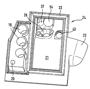
Fig. 2 shows a perspective view of the tank housing (10). Formed onto the
first moulded shell (24) facing away from the parting-off wheel (2) is a tank
connector (23) which opens into the fuel tank (12) and serves to fill the fuel
tank. Formed onto the first moulded shell (24) is a connector (26) which
connects the clean air side (44) of the air filter unit (8) to the carburettor
(5). In addition to the air filter unit (8), the air cleaning unit also
contains a
cyclone unit (17) which comprises several cyclone tubes (19). The cyclone
tubes (19) are aligned approximately along the longitudinal axis (16) of the
parting-off grinder (1) and formed onto the moulded shells (24 and 25).
Provided at the end of the cyclone tubes (19) facing the parting-off wheel
(2) is a tangentially running inlet (27) into the cyclone tubes (19). In the
area of the base (53) of the tank housing (10), the second moulded shell
(25) has a straight section (29) which extends towards the parting-off wheel
(2). Located in the straight section (29) are four holes (28) through which
the two-stroke engine (15) can be screwed to the tank housing (10). The
two-stroke engine is thus screwed to the straight section (29) from the base
(53).
Fig. 3 shows the first moulded shell (24) of a tank housing (10).
Components which are identical to those illustrated in Figs. 1 and 2 are
designated by the same reference numerals. Formed onto the air filter base
(21) is a peripheral sealing edge (22) in which the seal (35) shown in Fig. 1
is held. The seal (35) seals the air filter housing (34) against the air
filter
base (21). Also provided in the moulded shell (24) shown in Fig. 3, in
addition to the connector (26) leading to the intake duct (4), is a connector
(37) which carries an air duct (54). Formed onto the first moulded shell
(24) are cyclone tubes (19) and a return (20). The return (20) serves to carry
the dirt separated in the cyclone tubes (19) away to the fan wheel of the
parting-off grinder (1). Provided in the air filter base (21) is a bleed
opening (43) via which the tank housing (10) is connected to the clean air
side (44) of the air filter unit (8). The bleed valve (50) illustrated in Fig.
1
which is designed as a mushroom valve can be connected to the bleed
CA 02467608 2004-05-19
6
opening (43). The valve (50) has a valve member (52) which lies on the air
filter base (21). As the pressure increases, the valve member (52) lifts off
the air filter base (21) and air is able to flow through the duct (51) onto
the
clean air side (44) of the air filter unit (8). Instead of the valve (50), it
is
also possible to use another valve, for example an aeration valve, or a
complete assembly.
Fig. 5 shows the first moulded shell (24) from the side facing the second
moulded shell (25). The tank housing (10) contains an equalising reservoir
(13). The bleed opening (43) is positioned in a reservoir wall (63) of the
equalising reservoir (13). The bleed opening (43) is connected to the
equalising reservoir (13) via a bleed line (42). The bleed line (42) runs
along the roof (55) of the tank housing (10) in the parting plane (36) of the
two moulded shells (24, 25) and is formed onto the two moulded shells (24,
25). The cyclone tubes (19) and the return (20) pass through the equalising
reservoir (13). In this arrangement a section (45) of the cylinder tubes (10)
is formed onto the first moulded shell (24) and a further section (46),
illustrated in Fig. 6, is formed onto the second moulded shell (25).
Similarly, a section (47) of the return (20) is formed onto the first moulded
shell (24) and a section (48) is formed onto the second moulded shell (25).
The equalising reservoir (13) is connected to the fuel tank (12) via an
equalising line (38). The equalising line (38) has a connection to the fuel
tank (12) in an area (57) so that air is preferably able to flow into the
equalising line (38) for pressure equalisation. The area (57) is positioned in
the area of the roof (55) of the tank housing (10). The equalising line (38)
passes through the area (57) in the manner of a labyrinth. The equalising
line (38) then runs through the area of the roof (55) of the tank housing (10)
and along a lateral wall (56) of the fuel tank (12). In the area of the
lateral
wall (56) the equalising line (38) passes between the cyclone tubes (19) and
the lateral wall (56). The equalising line (38) then extends through the area
CA 02467608 2004-05-19
7
of the base (53) of the tank housing (10) to an outlet (58) in the equalising
reservoir (13).
The wall (39) of the tank housing (10) is designed with double walls and
has reinforcing struts (40). In this arrangement the double wall (39) runs
along the longitudinal sides (61 and 62) of the tank housing (10) and along
the base (53).
As shown in Fig. 6, the bleed line (42) has an inlet (59) at which it opens
into the equalising reservoir (13) in the area of the roof (55). At the other
end of the equalising line (42) a cover section (49) is formed onto the
second moulded shell (25) which seals the equalising line (42) in the area
of the bleed opening (43). Reinforcing struts (60) are formed onto the
second moulded shell (25) in the area of the roof (55).
The bleed line (42) and the equalising line (38) are formed onto the two
moulded shells (24 and 25) and pass through the inside of the tank housing
(10). Similarly, the bleed opening (43) forms an opening in an inner wall,
i.e. the air filter base (21). This avoids leaks on the outside of the tank.
The
tank housing (10) is advantageously made of plastic. The two moulded
shells (24 and 25) are usefully joined together by means of welding, in
particular hot gas welding.
In the event of overpressure in the fuel tank (12) air is able to follow into
the equalising reservoir (13) during operation via the equalising line (38).
To further reduce pressure air is also able to flow to the clean air side (44)
of the air filter unit (8) via the bleed line (42) and the bleed opening (43).
Fuel carried with it is either aspirated into the carburettor (5) from the
clean
air side (44) or collects at the base of the equalising reservoir (13) from
where it flows back to the fuel tank (12) via the equalising line (38). It may
be useful for the fuel tank to be connected directly to the clean air side
(44)
CA 02467608 2004-05-19
8
of the air cleaning unit via a bleed opening and no equalising reservoir (13)
to be provided.
CA 02467608 2004-05-19