Note: Descriptions are shown in the official language in which they were submitted.
CA 02467779 2009-07-15
CORDLESS SOLDERING IRON
This space intentionally left blank.
FIELD OF THE INVENTION
The present invention relates to cordless electrical devices, more
specifically, to
soldering irons and soldering iron tips.
BACKGROUND OF THE INVENTION
In many industries and for some hobbyists, it is necessary to manually make
electrically conductive connections between various electrical components. In
order to
make such connections, a wide variety of soldering irons have been developed,
for use in
a variety of applications, ranging from repair of printed circuit boards, use
in the
telecommunications industry, and use in the manufacture and repair of heavy
industrial
electrical and electromechanical equipment. Existing soldering irons vary by
power
source, application, performance, shape, size, temperature, tip type, heat
source, price,
and portability.
Regardless of the size or capability of the soldering iron, existing soldering
iron
tips are generally categorized into two main types. The first consists of a
heating element
surrounded by a non-conductive film material, which is then covered by a
thermally
conductive metallic shell. The tip is heated by the application of electricity
to the heating
element. Depending on the application, the tip size can vary widely. The power
source
may also vary, ranging from 2.4 volt batteries through a 220 volt alternating
current
conventional outlet. Regardless of the power source, the flow of electricity
to the heating
element is typically controlled by a switch in the electrical circuit leading
to the heating
element. The switch is often a manual switch located on the outer case of the
soldering
iron.
An alternate soldering iron tip includes a solid tip of a thermally conductive
material, usually a metal, which is heated by burning butane. Such soldering
irons are
typically portable, and the butane is supplied from a cartridge within the
tool.
-1-
CA 02467779 2004-05-07
WO 03/051568 PCT/US01/48265
A number of problems exist with the current types of soldering irons.
Soldering
irons that must be plugged into a conventional electrical outlet lack mobility
and are
restrictive in use. Regardless of the tip type, the time generally required to
reach
soldering temperatures initially ranges from 10 to 60 seconds. If the
soldering iron has
not completely cooled down between uses, subsequent uses may not require as
much
startup time, but are still not immediate. Similarly, the time required for
desired cooling
can be substantial, posing the danger of burns to the operator and his or her
surroundings
after the tool has been removed from the work surface and before the tool has
cooled.
Furthermore, metal tips may become soldered to the connection, damaging the
connection as the tip is removed and requiring further repair.
Existing cordless soldering irons resolve the mobility issues with soldering
irons
connected to conventional outlets, but at the cost of further problems. Butane
irons
require the operator to store and maintain a highly flammable gas and do not
resolve the
other deficiencies noted above. Existing battery-powered cordless soldering
irons can
typically make only 125 connections per full charge and are only capable of
equivalent
power output in the range of about 15-25 watts.
In order to ensure that the operator is able to adequately view the joint to
be
soldered, existing electric soldering irons are sometimes provided with a
small lamp
disposed on the soldering iron to illuminate the tip and connection. In these
devices, the
light is controlled by the same switch that controls the flow of electricity
to the heating
element. A disadvantage of this system is the inability to use the light
without heating the
tip of the soldering iron. This requires the operator to carry a separate
flashlight if he or
she wishes to illuminate the surroundings without soldering or heating.
As noted above, soldering irons are primarily used for making electrically
conductive connections in various forms of electrical and electronic
equipment. A visual
inspection of the soldered connection may not always accurately determine
whether or
not the connection has been formed correctly and is now electrically
conductive.
Therefore, those operators who wish to test their connection, or to test
electrical
continuity between any two other points in the circuit, must carry a separate
continuity
tester.
Thus, a need exists for a soldering iron that can heat up and cool down
quickly,
minimizing the risk of burning the operator and/or his or her surroundings.
Ideally, the
-2-
CA 02467779 2004-05-07
WO 03/051568 PCT/US01/48265
soldering iron would be portable and could be used to form a large number of
connections at high power output without having to be recharged. There is a
further need
for a portable soldering iron which can also be used as a flashlight and/or a
continuity
tester, reducing the number of tools to be carried by the operator to the site
of the work.
SUMMARY OF THE INVENTION
Generally described, the present invention provides a soldering iron, with a
graphite tip having two separate halves that are electrically isolated from
one another.
The tip halves are each electrically connected to the opposite sides of an
electrical power
source. When both halves of the tip are applied to an electrically conductive
material,
such as the material to be soldered, an electrical circuit between the tip
halves and
electrical power source is completed. The halves of the tip are constructed
from material
having high electrical resistivity and low thermal conductivity. Therefore,
the tip can
reach operating temperatures quickly. When the tip is removed from the joint,
the
electrical circuit is broken and the tip material quickly cools.
Because electricity is only able to flow when the two pieces of the tip are
electrically connected, no separate switch is required. Furthermore, the
soldering iron
may be used without waiting for the tip to heat. The tip also reduces the risk
of burning
the operator and/or his or her surroundings because it heats up and cools down
quickly.
Furthermore, the tip material eliminates the risk of the tip becoming stuck in
the joint.
The tip material also permits higher power outputs than other known battery-
operated
portable soldering irons and permits over 300 joints for each full charge.
In accordance with further aspects of the present invention, in one
embodiment,
the soldering iron also includes a light disposed on the case to illuminate
the tip and
connection. The light is controlled by a separate switch and permits the tool
to be used to
illuminate the operator's surroundings without actually having to heat the
tip. This aspect
of the invention permits the operator to avoid the necessity of carrying a
separate light
source when working or intending to work in areas without sufficient lighting.
In accordance with other aspects of the invention, another embodiment is
provided in which the tool also includes an electrical lead connected in
series with the
lamp, the power source, and a continuity testing probe. This aspect of the
invention
permits the soldering iron to test circuit continuity by applying the lead and
the probe
directly to a newly soldered connection, or to another part of the circuit to
be tested. This
-3-
CA 02467779 2004-05-07
WO 03/051568 PCT/US01/48265
aspect of the invention permits the operator to avoid the necessity of
carrying a separate
continuity tester to perform this function.
BRIEF DESCRIPTION OF THE DRAWINGS
The foregoing aspects and many of the attendant advantages of this invention
will
become more readily appreciated as the same become better understood by
reference to
the following detailed description, when taken in conjunction with the
accompanying
drawings, wherein:
FIGURE 1 is an elevation view of one embodiment of a soldering iron formed in
accordance with the present invention;
FIGURE 2 is a front elevation view of one embodiment of a soldering tip formed
in accordance with the present invention;
FIGURE 3 is a side elevation of the soldering tip illustrated in FIGURE 2;
FIGURE 4 is an end view of the soldering tip shown in FIGURE 2; and
FIGURE 5 is a circuit diagram for use with the embodiment of FIGURE 1.
DETAILED DESCRIPTION OF THE PREFERRED EMBODIMENT
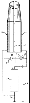
Referring to FIGURE 1, one embodiment of a cordless soldering iron formed in
accordance with the present invention is shown. The soldering iron I includes
a tip 2
attached to a body 3, an electric light 4 disposed on the body 3 to illuminate
the tip 2 and
surrounding work surfaces (not shown), a switch 5 disposed on the body 3 to
control the
electric light 4, a continuity testing lead 6 and a continuity testing probe 7
disposed on
body 3, and an electrical power means 8 (see FIGURE 5).
In more detail, the body 3 includes an elongate substantially tubular member
of
rigid heat resistant material, such as plastic or other materials known to
those skilled in
the art. The body is a unitary structure, assembled in parts, and configured
to hold the
sub-components described below. Those skilled in the art will recognize that
the
configuration of the body can vary widely for use in different applications.
Referring to FIGURES 2, 3 and 4, the tip 2 includes two electrodes 9 and 10,
electrically isolated from one another by an insulator 11 disposed
therebetween. In the
case of the embodiment illustrated in FIGURES 2, 3, and 4, the electrodes 9
and 10 are
cross-sectionally shaped as half cylinders. In the longitudinal direction,
each electrode is
conically tapered along its distal third at an angle A and is further
truncated at the distal
tip by an angle B, thereby forming a flat, angled surface for application to
the joint to be
-4-
CA 02467779 2004-05-07
WO 03/051568 PCT/US01/48265
soldered. Those skilled in the art will recognize that the size and shape of
the tip can also
vary widely for use in different soldering applications.
The electrodes 9 and 10 are preferably formed of graphite, or a material
containing graphite. For example, battery electrodes containing graphite, such
as battery
electrodes obtained from Eveready Super Heavy Duty Lantern Battery Model No.
1209, manufactured by Eveready Battery Company, Inc., Cleveland, Ohio, have
provided
acceptable results. The electrodes may alternatively be formed from other
materials that
are semi-conductive electrically, and which have low thermal conductivity, for
example
germanium or silicon. The electrical resistivity of the tip materials should
be at least
1,500 micro-Ohm cm. and is preferably over 3,000 micro-Ohm cm., while the
thermal
conductivity should be less than 10 BTU/hr-ft- F and is preferably in the
range of 1 to 10
BTU/hr-ft- F. Upon the application of electricity, the electrode material
reaches a
temperature of approximately 600 F within a few seconds, and remains a solid
at
temperatures in excess of about 1,000 F. Furthermore, the electrode material
preferably
has sufficient compressive and tensile strength to permit the electrodes to be
manufactured to tolerances of less than about 1 mm, rigidly held in place by
the body 3
and applied to the connection to be soldered without mechanical failure. The
tip should
have a density in the range of 1.5 to 1.75 g/cc and a minimum flexural
strength of 1,500
psi.
In one embodiment, the insulator 11 is formed of mica. The insulator 11 may
alternatively be formed of a solid dielectric material that is able to
withstand temperatures
in excess of about 1,000 F without changing state.
The tip 2 is attached in any conventional manner, preferably in detachable
manner, to the body 3. Those skilled in the art will recognize that the means
of attaching
and detaching the tip to the body can vary widely for use in different
soldering
applications. Making the tip detachable also permits the use of different tips
for different
applications with the same tool. When secured, the electrodes 9 and 10 are
separately
electrically connected to the positive and negative terminals of an electrical
power
means 8 in a conventional manner. A variety of electrical power means 8 can be
used,
including rechargeable or non-rechargeable batteries, or low voltage provided
from line
voltage through a transformer. Electrical power means in FIGURE 1 are a pair
of nickel
cadmium batteries encased within the body 3 to provide a nominal voltage of
2.4 volts
-5-
CA 02467779 2004-05-07
WO 03/051568 PCT/US01/48265
and 700-750 milliamp hours. Electrodes 9 and 10 can optionally be electrically
isolated
from the electrical power means 8 by a switch or other means for interrupting
the flow of
electricity in an electrical circuit.
When both electrodes 9 and 10 are applied to an electrically conductive or
semi-
conductive material, such as solder, an electrical circuit is completed from
the positive
terminal of electrical power means 8, through electrode 9, through the
electrically
conductive or semi-conductive material to which the tip has been applied,
through
electrode 10 and back to the negative terminal of electrical power means 8.
The flow of
electricity causes electrodes 9 and 10 to heat to a temperature of about 600 F
or greater
within a few seconds, allowing the tool to thereafter be used in the same
manner as a
conventional soldering iron. As configured, the apparatus provides an
alternating current
equivalent of about 25 - 50 watts of heat to the joint to be soldered. An
additional
property of the preferred material for the electrodes is that it cannot become
soldered to
the joint while being used. When the operator of the apparatus wants to cease
the
application of heat, the apparatus can be removed from the electrically
conductive or
semi-conductive material, interrupting the flow of electricity. When the
electricity is
interrupted, the electrodes cool to a temperature safe for contact with human
skin or
clothing within a few seconds.
The apparatus optionally includes a conventional electric light 4, for
example, an
incandescent light bulb or light emitting diode. As shown on FIGURE 1, the
light 4 is
positioned on the body 3 so that the light emitted will illuminate the tip 2
and the
surrounding work area during use. As shown on FIGURE 5, the light 4 is
conventionally
electrically connected to the electrical power means 8 and controlled by the
switch 5.
When switch 5 is closed, the circuit is completed from one terminal of the
electrical
power means 8, through the switch 5, through the electric light 4, and back to
the
opposite terminal of electrical power means 8, illuminating the electric light
4 without
applying electricity to the tip 2. Because electric light 4 may be switched on
without
heating the tip 2, the light may be used to illuminate the surroundings of the
operator
without risk of accidentally burning the operator or nearby combustible
materials.
As shown in FIGURE 1, the apparatus may further optionally be provided with a
continuity testing assembly having a continuity testing lead 6 and a
continuity testing
probe 7. The lead 6 further includes a wire 12, for example, a 26 gauge wire,
extending
-6-
CA 02467779 2004-05-07
WO 03/051568 PCT/US01/48265
from the body 3 at one end and with an alligator clip 13 attached at the
distal end of the
wire 12. The continuity testing probe 7 is a probe similar to those used in
conventional
electrical test equipment, for example, a short, rigid, electrically
conductive needle-
shaped probe. It will be readily apparent to those skilled in the art that the
continuity
testing lead and continuity testing probe can be formed of any electrically
conductive
material without departing from the spirit and intention of the invention. As
shown in
FIGURE 5, the continuity testing lead 6 is electrically connected to the
electrical power
means 8 via a path extending through the electric light 4. The probe 7 is
connected to the
opposite terminal of the power means 8. Referring to FIGURE 5, the tip is
connected in
series to the power means 8. A path 20 is provided in parallel with the tip.
The light 4
and the switch 5 are placed in series along the path 20. The lead 6 is
connected to the
path 20 at connection 22 located between the light 4 and switch 5. The
assembly is used
to test circuit by affixing alligator clip 13 to one side of the circuit to be
tested and
touching the probe 7 to the opposite side of the circuit. If the circuit being
tested is
electrically continuous, current will flow from the electrical power means 8,
through the
electric light 4, through the continuity testing lead 6, through the circuit
being tested,
through the continuity testing probe 7, and back to electrical power means 8,
thus
completing the circuit and illuminating electric light 4. The illumination of
the light 4
quickly demonstrates the continuity of the tested circuit. This embodiment is
particularly
useful for cordless soldering irons, since the operator can test the soldered
joint without
having to obtain or carry a separate tool.
As shown in FIGURE 1, end caps 14 and 15 are available to protect the tip 2
and
continuity testing lead 6 from damage. The end caps are removably fixed to the
body 2
by conventional means, for example, a friction fit, a clamp, threaded
surfaces, etc.
While the preferred embodiment of the invention has been illustrated and
described, it will be appreciated that various changes can be made therein
without
departing from the spirit and scope of the invention.
-7-