Note: Descriptions are shown in the official language in which they were submitted.
CA 02467950 2004-05-21
11924DE 2004-05-12 1
BLASTING APPARATUS FOR THE BLASTING OF A ROCK DRILL BIT
Technical Field of the Invention
The present invention relates to a blasting apparatus for the
blasting of a rock drill bit, such as the same is defined in the preamble of
the
appended independent claim.
When rock drill bits are used, the cemented carbide buttons are
worn so that the rock drill bit has to be disassembled and the buttons be
ground
by means of, for instance, a grinding cup of the type shown in US-A-5,964,649.
If the buttons have been worn so much that the same cannot be reground,
there is a plurality of ways to machine the surrounding steel on the front
surface
of the drill bit, such as blasting, grinding or milling, in order to obtain
the requi-
site cemented carbide material. By SE-A-7609765-8, it is previously known to
blast rock drill bits. One problem in blasting is that the surrounding parts
of the
blasting equipment, such as a hood, is damaged or eroded during the blasting
process. Another problem is that the known technique requires large amounts
of air, and thereby expensive compressors. Other known blasting machines are
shown in US-A-5,029,595 and WO-A1-9105635.
Objects of the Invention
One object of the present invention is to provide a blasting
apparatus for the blasting of rock drill bits, which avoids the disadvantages
of
prior art.
Another object of the present invention is to provide a blasting
apparatus for the blasting of rock drill bits, which does not erode other
equipment in the blasting apparatus.
Another object of the present invention is to provide a blasting
apparatus for the blasting of rock drill bits, which reduces the consumption
of
air.
CA 02467950 2004-05-21
11924DE 2004-05-12 2
Another object of the present invention is to provide a blasting
apparatus for the blasting of rock drill bits, which is simple to use.
Another object of the present invention is to provide a blasting
apparatus for the blasting of rock drill bits, which is careful towards the
abrasive
particles of the blasting medium.
The above-mentioned objects of the present invention are realized
by means of a blasting apparatus for the blasting of a rock drill bit, such as
it is
defined in the features in the appended claims.
Description of the Drawings
Below, an embodiment of a blasting apparatus for the blasting of a
rock drill bit according to the present invention will be described, reference
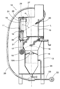
being made to the appended drawings. Fig. 1A shows a blasting apparatus
according to the present invention in a perspective view. Fig. 1 B shows the
blasting apparatus in cross-section. Fig. 1C shows the blasting apparatus in
perspective view having an opened hood. Fig. 1 D shows a fixture in the
blasting
apparatus in perspective view. Fig. 1 E shows a part of the blasting apparatus
and Fig. 1 F shows an enlarged detail of the part according to Fig. 1 E in
enlargement.
Detailed Description of the Invention
Reference being made to Figs. 1A-1 F, hereinafter a blasting
apparatus 10 according to the present invention is described, for blasting of
steel from a front surface 11 of a rock drill bit 12. The blasting apparatus
10
comprises a support part 13 and a hood or first chamber 14. The hood 14 is
openable in relation to the support part via hinges and is preferably rubber
lined
internally. The support part 13 comprises a pressure tank 15 intended to hold
blast sand, a collecting member 16 in order to collect down-falling blast sand
and metal particles, a rotatable fixture 17 connected to a rotation motor 18,
and
a stand 19 in order to hold a blast nozzle 20. The blast nozzle 20 conducts a
pressurized blast medium towards the rock drill bit 11 in a direction L. The
rock
drill bit 11 is intended to, in a simple way, be fastened in the fixture and
be
CA 02467950 2004-05-21
11924DE 2004-05-12 3
rotated by about 15-20 revolutions per minute. The fixture 17 has an upper
releasable part 21, the geometry of which is adapted to the bit shape in ques-
tion. A schematically shown compressor 22 is intended to feed the blasting
apparatus 10 with pressurized air via pipes. The pressure tank has a non-
return
valve 15A. In connection with the pressure tank 15, suitable valves are
arranged.
In the example shown, the hood 14 has substantially a box shape.
A hollow damper or a second chamber 26, partially open at least from the side,
is mounted hanging in an upper part 27 of the hood. The second chamber is
thus mounted in the first chamber. The hood has an elevated part in order to
house a stand and a part of a pipe 25 as well as a recess for a dust
collector.
The pipe 25 is positioned within the apparatus 10 but has for the sake of
clarity
been drawn outside the same in Fig. 1 B. The damper has during tests
consisted of a steel-reinforced rubber tube having a material thickness of 10
mm and an inner diameter of 200 mm. By the term "tube" is meant that also
tubes with non-circular cross-sections are included.
The damper 26 is substantially tubular and so mounted in the
upper part that it may oscillate around an axis X defined by two diametrically
opposite spigots 28 co-operating with the corresponding holes in the damper
26. The axis X is substantially perpendicular to the rotational axis of the
fixture
17. Thereby, the damper is at least partially movable in said direction L and
the
free end 30 of the damper is pivotable in said direction L. Furthermore, the
spigots 28 are connected to the upper part 27 by means of, for instance,
screws. An additional protective plate 29 is arranged between the damper and
the upper,part. The protective plate 29 is preferably rubber lined in order to
decrease erosion on the upper part. The damper 26 is arranged to, at least
partially, enclose the releasable part 21 of the fixture. The damper has an
opening 31, the position of which in relation to the nozzle 20 is controlled
by the
spigots 28. The opening 31 is located between the releasable part 21 and the
blast nozzle 20.
The damper 26 has a substantially U-shaped cross-section at the
opening 31. The damper is at least long enough for the free end 30 to reach be-
CA 02467950 2004-05-21
11924DE 2004-05-12 4
neath the front of the releasable part 21 when the damper hangs assembled in
the hood, preferably a distance down into the support part 13.
The blasting apparatus 10 operates in the following way, reference
foremost being made to Fig. 1 B. The hood 14 is opened and blast sand is
charged in the tank 15 through the open non-return valve 15A. The rock drill
bit
12 is applied in the upper part 21 of the fixture, conveniently so that the
parts of
the bit that are not to be blasted, such as threads or splines, are protected
by
the upper part 21. The blast nozzle 20 is adjusted along the stand 19 so that
the centre line of the nozzle forms an acute angle a of maximum 45 ,
preferably
about 42-43 to the rotational axis of the fixture 17, in order to conduct the
pressurized blast medium towards the rock drill bit 11 in a direction L. The
noz-
zle 20 is arranged about 7-10 cm from the drill bit or the fixture. Then, the
hood
14 is closed and is locked. Subsequently, the compressor is started 22 so that
the tank 15 is pressurized via the pipes 23 and 24. Thereby, sand is forced
down through a valve having suitable throughput capacity and outwards into the
pipe 25 to be forwarded to the nozzle 20. Preferably, the motor 18 is started
at
the same time as the compressor. Thereby, the sand is blown in the direction L
towards the front surface 11 through the opening 31 in the damper 26 and cuts
steel from the front surface while the rock drill bit rotates. The blast sand
then
bounces on towards the damper 26 so that the damper oscillates in the direc-
tion towards the nearest wall in the hood 14. The speed of the individual sand
particles is damped substantially by the motion of the damper. The cemented
carbide buttons in the front surface remain substantially unaffected by the
blasting. Regarding the object of reduced air consumption the theory is that
at
least a part of the blasting medium is recirculated in the second chamber
after
initial hitting against the drill bit front face for quickly reverting into
the blasting
stream and thereby further blasting the drill bit. Our tests have shown an
increased productivity. A faster machining consequently provides reduced air
consumption per drill bit. It has turned out in tests that the pressure
performance of the compressor could be lowered by 50 % to 5,5 bar and that
the air consumption decreased by 75 %. Thereby, the blasting apparatus may
be used together with inexpensive compressors. Because of the motion of the
CA 02467950 2010-06-17
damper 26, substantially no erosion of the hood 14 takes place so less hood
walls need rubber lining. Furthermore, because of the oscillation, the blast
stream is directed downwardly in the direction towards the pressure tank so
that
the sand returns fast to the tank.
5 It is implicit that the blasting apparatus may be modified within the
scope of the present invention. For instance, the oscillating mounting of the
damper may be arranged in other ways, such as by means of a flexible inter-
mediate portion or the like. Furthermore, the material in the damper may be
varied.
Thus, the present invention relates to a blasting apparatus for the
blasting of rock drill bits, which does not erode other equipment, which
requires
relatively small amounts of air, which is simple to use, and which is careful
towards the abrasive particles of the blasting medium.
The disclosures in Swedish patent application No. 0301675-5.
Other embodiments of the invention will be apparent to those
skilled in the art from a consideration of the specification or practice of
the
invention disclosed herein. It is intended that the specification and the
example
be considered as illustrative only, with the true scope of the invention being
indicated by the following claims.