Language selection

Search

Patent 2468186 Summary

Third-party information liability

Some of the information on this Web page has been provided by external sources. The Government of Canada is not responsible for the accuracy, reliability or currency of the information supplied by external sources. Users wishing to rely upon this information should consult directly with the source of the information. Content provided by external sources is not subject to official languages, privacy and accessibility requirements.

Claims and Abstract availability

Any discrepancies in the text and image of the Claims and Abstract are due to differing posting times. Text of the Claims and Abstract are posted:

  • At the time the application is open to public inspection;
  • At the time of issue of the patent (grant).
(12) Patent: (11) CA 2468186
(54) English Title: REVOLVABLE PLUG AND SOCKET
(54) French Title: FICHE TOURNANTE ET PRISE MURALE
Status: Deemed expired
Bibliographic Data
(51) International Patent Classification (IPC):
  • H01R 39/00 (2006.01)
  • H01R 35/04 (2006.01)
  • H01R 13/73 (2006.01)
(72) Inventors :
  • KOHEN, RAN (Israel)
(73) Owners :
  • SAFETY QUICK LIGHT LTD. (Israel)
(71) Applicants :
  • SAFETY QUICK LIGHT LTD. (Israel)
(74) Agent: LAVERY, DE BILLY, LLP
(74) Associate agent:
(45) Issued: 2010-09-28
(86) PCT Filing Date: 2001-11-22
(87) Open to Public Inspection: 2003-05-30
Examination requested: 2006-09-28
Availability of licence: N/A
(25) Language of filing: English

Patent Cooperation Treaty (PCT): Yes
(86) PCT Filing Number: PCT/IL2001/001078
(87) International Publication Number: WO2003/044906
(85) National Entry: 2004-05-25

(30) Application Priority Data: None

Abstracts

English Abstract


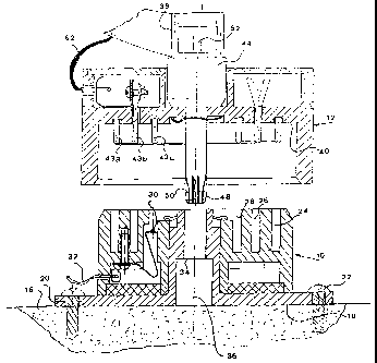
The invention relates to the support of light electric appliances such as
light fittings and small fans. The device (Fig. 2) accoring to the invention
provides a plug (12) and socket (10) combination powering and supporting an
appliance in a manner allowing the user to change its orientation. The
combination is particularly useful where there is a frequent need to move
light appliances from one location to another. The combination comprises a
fixable socket (20) and a plug (12) revolvable therein for conducting electric
power and for mechanically supporting in a desired orientation an appliance
receiving the power.


French Abstract

L'invention a trait au support d'appareils électriques légers tels que luminaires et petits ventilateurs. Le dispositif de l'invention combine une fiche tournante (12) et une prise murale (10) permettant d'alimenter et de soutenir un appareil de sorte que l'utilisateur puisse changer l'orientation de celui-ci. Cette combinaison est particulièrement utile lorsque des appareils légers doivent être déplacés fréquemment. Ladite combinaison comprend une prise murale (20) pouvant être fixée et une fiche (12) capable de tourner dans celle-ci pour alimenter en courant électrique et soutenir mécaniquement dans une orientation voulue l'appareil branché.

Claims

Note: Claims are shown in the official language in which they were submitted.


CLAIMS
1. A combination of a fixable socket and a plug revolvable therein
for conducting electric power and for mechanically supporting in a desired
orientation an appliance receiving said power, said combination comprising:
a) a socket rigidly attachable to a wall or ceiling, said socket
comprising a non-conductive body including at least two spaced-apart hollow
arcuate conducting receptacles insulated from each other and having a
common center of curvature and being connectable to an electric power
supply, said socket rigidly supporting a first structural element of a
mechanical connection located at said center of curvature;
b) a plug also comprising a non-conductive body, rigidly attachable to,
and configured to mechanically support an appliance from a first face, said
plug supporting from a second face at least two projecting conducting prong
elements insulated from each other and engageable with said at least two
arcuate receptacles respectively and connectable to conductors for feeding
electric power to said appliance, said plug also including a second structural
element engageable to said first structural element of said mechanical
connection and allowing said plug to revolve at least part of a revolution
about
said center of curvature; and
c) releasable latching means attached to said combination, providing
when engaged a retention force between said socket and said plug to prevent
disengagement and to support said appliance.

2. The socket and plug combination as claimed in claim 1, wherein
said first structural element comprises an aperture and said second structural
element comprises a post-like male member engageable with said aperture.

3. The socket and plug combination as claimed in claim 2, wherein
said releasable latching means is a captive ball decent.


4. The socket and plug combination as claimed in claim 2, wherein
both parts of said mechanical connection are conductive and are arranged to
be wired for use as an earth connection.

5. The socket and plug combination as claimed in claim 1, wherein
said latching means engages said first structural element with sufficient
retention force to support a two kg appliance in a ceiling socket during an
earthquake of a severity not causing structural damage to the building in
which said combination is installed.

6. The socket and plug combination as claimed in claim 1, wherein
said appliance is an electric light fitting.

11

Description

Note: Descriptions are shown in the official language in which they were submitted.


CA 02468186 2009-01-08

REVOLVABLE PLUG AND SOCKET
FIELD AND BACKGROUND OF THE INVENTION

The present invention relates to the support of light electric appliances
such as light fittings and small fans.

More particularly, the invention provides a plug and socket combination
powering and supporting an appliance in a manner allowing the user to
change its orientation. The combination is particularly useful where there is
a
frequent need to move light appliances from one location to another.

In a previous disclosure, Israel Patent no. 126246, the present
inventors described a socket and plug combination for conducting electric
power and for mechanically supporting a light-weight appliance by means of
said plug. Such appliance can be a light, camera, small TV receiver, TV
camera, a small fan or the like.

In our earlier patent the socket has prong-receiving receptacles similar
to those found on conventional sockets. Consequently, after the appliance
was plugged into the socket, which itself was rigidly attached to a wall or
ceiling, the orientation of the appliance attached to the plug could no longer

be changed. Where the item being installed is substantially symmetrical, for
example a common incandescent filament lamp mounted in a cylindrical lamp
socket, such restriction is meaningless. There are however many lighting
fixtures with reflectors which


CA 02468186 2004-05-25
WO 03/044906 PCT/1L01/01078

need to be oriented in a certain direction, or may be expected to serve a user
in
two proximate but different locations. With regard to a non-oscillating fan,
or a
small television camera or receiver, directional orientation is most important
for
effective use thereof.

In US Patent no. 4,753,600 Williams discloses an electrical connector for
io use with hand tools joined to drop cords. The connector is placed in the
cord and
allows unlimited rotation without twisting the cable. The connector is not
attachable
to a building surface and can not support any load.

The rotatable electric connector proposed by Salzberg in US Patent no.
6,068,490 is arranged to be plugged into a wall socket but not to support any
load
therefrom apart for its own weight. A revolvable portion carries a cable
terminated
by an electric socket.

OBJECTS OF THE INVENTION

It is therefore one of the objects of the present invention to obviate the
limitations of prior art electrical plugs and sockets and to provide an
assembly
which is configured to both support and power a revolvable load, i.e. an
electric
appliance.

It is a further object of the present invention to reduce cost by providing an
embodiment for single phase supply line requiring only two slip rings in place
of the
three slip rings in prior-art revolvable plugs.

2


CA 02468186 2004-05-25
WO 03/044906 PCT/1L01/01078

SUMMARY OF THE INVENTION

The present invention achieves the above objects by providing a
combination of a fixable socket and a plug revolvable therein for conducting
electric power and for mechanically supporting in a desired orientation an
io appliance receiving said power, said combination comprising:

a) a socket rigidly attachable to a wall or ceiling, said socket comprising a
non-conductive body including at least two spaced-apart hollow arcuate
conducting
receptacles insulated from each other and having a common center of curvature
and being connectable to an electric power supply, said socket rigidly
supporting a

first structural element of a mechanical connection located at said radius of
curvature;

b) a plug also comprising a non-conductive body, rigidly attachable to,
and configured to mechanically support an appliance from a first face, said
plug
supporting from a second face at least two projecting conducting prongs
insulated

from each other and engagable with said at least two arcuate receptacles
respectively and connectable to conductors for feeding electric power to said
appliance, said plug also including a second structural element engagable to
said
first structural element of said mechanical connection and allowing said plug
to
revolve at least part of a revolution about said center of curvature; and

3


CA 02468186 2004-05-25
WO 03/044906 PCT/1L01/01078

s c) releasable latching means attached to said combination, providing when
engaged a retention force between said socket and said plug to prevent
disengagement and to support said appliance.

In a preferred embodiment of the present invention there is provided a
socket and plug combination wherein said first structural element comprises an
io aperture and said second structural element comprises a post-like male
member
engagable with said aperture.

In a most preferred embodiment of the present invention there is provided
socket and plug combination wherein both parts of said mechanical connection
are
conductive and are arranged to be wired for use as an earth connection.

15 Yet further embodiments of the invention will be described hereinafter.

It will thus be realized that the novel connector of the present invention
serves to allow fast installation of small electrical appliances. Unlike the
industrial
bus-bar, the present invention maintains a standard of appearance appropriate
to
residential areas. The ability of varying the orientation of the supported
appliance is

20 additional to the facility of fast exchange for another appliance fitted
with a plug
according to the present invention.

The present specification does not describe a locking device for retaining
the plug in a desired orientation, which is a desirable addition. The prior
art
however describes many types of locking, braking, detent or location retention

25 device, and an appropriate locking device can easily be added to the plug-
socket
combination of the present invention to retain the plug in any desired
position.

4


CA 02468186 2004-05-25
WO 03/044906 PCT/1L01/01078
BRIEF DESCRIPTION OF THE DRAWINGS

The invention will now be described further with reference to the
accompanying drawings, which represent by example preferred embodiments of
the invention. Structural details are shown only as far as necessary for a
fundamental understanding thereof. The described examples, together with the

drawings, will make apparent to those skilled in the art how further forms of
the
invention may be realized.

In the drawings:

FIG. 1 is a non-detailed perspective view of a preferred embodiment of the
socket and plug combination attached to a wall, according to the invention;

FIG. 2 is a sectional elevational view of the same embodiment showing the
plug before engagement with socket;

FIG. 3 is a sectional elevational view of an embodiment attached to a
ceiling and supporting a fan;

FIG. 4 is a plan view of the socket seen in FIGS 1 and 2;

FIG. 5 is a detail sectional elevation of a second embodiment of the
release mechanism;

and
FIG. 6 is a perspective view of the plug-socket combination supporting a
lighting fixture.


5


CA 02468186 2004-05-25
WO 03/044906 PCT/1L01/01078

DETAILED DESCRIPTION OF THE PRESENT INVENTION

There is seen in FIGS. 1, 2 and 4 a combination of a fixable socket 10 and
a plug 12. The plug 12 is revolvable in the socket 10, and receives electric
power
therefrom. The combination 10 + 12 serves also for mechanically supporting in
a

io desired orientation a light appliance 14, in the present example a
miniature
television receiver, receiving said power.

The socket 10 is shown in the present figure attached to a wall 16, seen in
FIG. 2. The socket 10 has a flat base 18 and apertures 20 to allow the passage
of
screws 22. The socket 10 has a non-conductive body made of a plastic. Three

spaced-apart hollow arcuate conducting receptacles 24, 26, 28, seen most
clearly
in FIG. 4, are insulated from each other and have a common center of curvature
36. All three receptacles 24, 26, 28 comprise molded recesses containing
conductive inserts 30, one of which is seen in FIG. 2, which can be
permanently
connected by wires 32 to an electric power supply.

The socket 10 rigidly supports a first structural element 34, comprising a
cylindrical aperture, of a mechanical connection located at the center of the
radius
of curvature 36 of the conducting receptacles 24, 26, 28.

A plug 12 also made of a plastic is configured to match the socket 10. The
plug body is made of a plastic, and is somewhat larger than conventional plugs
to
enable the plug to rigidly support an appliance from a first face 38. The plug
10 has
6


CA 02468186 2004-05-25
WO 03/044906 PCT/1L01/01078

a second face 40 for mechanically supporting the conductive prong rings 43
a,b,c.
The appliance 14 weight is about 0.5 to 5 kg, depending on the support
configuration in the case of wall attachment. The shorter the distance between
the
wall 16 and the appliance center of gravity 42, the higher the load which can
be
supported.

Three projecting conducting prong rings insulated from each other are
positioned to be engagable with the three arcuate receptacles 24, 26, 28 of
the
socket 10, respectively. The prong rings are connected to conductors 62 for
feeding electric power to the appliance 14.

The plug 12 also supports a second structural element 44, engagable to
the first structural element 34 of the mechanical connection and allowing the
plug
12 to revolve at least part of a revolution about the center of curvature 36.

Preferably and as seen in the figure, the first structural element 34
comprises an aperture and the second structural element 44 comprises a post-
like
male member engagable with the aperture 34. The reverse order, that is where
the
socket 10 carries the male member, is also feasible.

Releasable latching means 46 retain the plug 12 in the socket 10, by
providing a retention force between the socket and the plug to prevent
disengagement and to support the appliance. In the present embodiment latching
means 46 comprises a split expandable post end 48 with a shoulder 50. An

internal shouldered push rod 52 is axially moved to expand the split end 48,
enabling the shoulder 50 to abut the aperture of the first structural element
44.

7


CA 02468186 2004-05-25
WO 03/044906 PCT/1L01/01078

s Latching means 48 are sized to engage the first structural element 44 with
sufficient retention force to support a two kg appliance 14 in a ceiling
socket during
an earthquake of a severity not causing structural damage to the building in
which
the combination is installed. Users will not expect an appliance to continue
to be
supported following a severe earthquake, which damages the building structure
io itself.

With reference to the rest of the figures, similar reference numerals have
been used to identify similar parts.

FIG. 3 shows an embodiment of an interconnected socket 10 and plug 54.
The socket 10 is seen attached to a ceiling 56. The plug 54 supports a fan 58,
15 which can be directed to face any desired direction by revolving the plug
54 in its

socket 10. The bowl-shaped cover 60 is added to improve appearance and to
prevent users making contact with electric wires 32, 62. The inner assembly is
similar to the plug 12 and socket 10 shown not yet interconnected in FIG. 2.

Referring now to FIG. 5, there is depicted a detail of a socket 64 and plug
20 66 combination wherein both parts 68, 70 of the mechanical connection are
conductive and are arranged to be wired for use as an earth connection. It
will be
appreciated that the earth plug prong ring, 43b in FIG. 2, is eliminated from
the
plug, an arcuate recess 26 in FIG. 2 is eliminated from the socket, and both
plug
and socket can be made smaller.

25 The socket 64 rigidly supports a first structural element 68 of a
mechanical
connection is located at the radius of curvature 36. Element 68 is a female
metal
8


CA 02468186 2004-05-25
WO 03/044906 PCT/1L01/01078

component molded into the plastic body 66. Due to the high stress on element
68,
a metal construction is in any case an advantage, thus opening the option of
utilizing the mechanical connection as an earth connector.

The retention mechanism in the present embodiment comprises a plurality
of hard captive balls 72 which are shown in the figure at their outer
position. The
balls 72 retain the plug 66 in the socket 64, as the post 70 can not be
withdrawn

through the element 68 while the balls 72 project outwards. Pushing the rod 74
inwards, against the compression spring 76 allows the balls 72 to retract into
a
recess 78 to allow withdrawal of the plug 66.

FIG. 6 shows a socket 80 and plug 82 combination similar to that seen in
FIG. 1. The appliance being powered and supported is an electric light fitting
84.
The hollow support arm 86 carrying cables 88 is attached to the side of the
plug
82. The light fitting 84 can be quickly installed, adjusted to radiate in a
desired
direction, and quickly removed when not needed - without the aid of tools.

The scope of the described invention is intended to include all
embodiments coming within the meaning of the following claims. The foregoing
examples illustrate useful forms of the invention, but are not to be
considered as
limiting its scope, as those skilled in the art will readily be aware that
additional
variants and modifications of the invention can be formulated without
departing
from the meaning of the following claims.

9

Representative Drawing
A single figure which represents the drawing illustrating the invention.
Administrative Status

For a clearer understanding of the status of the application/patent presented on this page, the site Disclaimer , as well as the definitions for Patent , Administrative Status , Maintenance Fee  and Payment History  should be consulted.

Administrative Status

Title Date
Forecasted Issue Date 2010-09-28
(86) PCT Filing Date 2001-11-22
(87) PCT Publication Date 2003-05-30
(85) National Entry 2004-05-25
Examination Requested 2006-09-28
(45) Issued 2010-09-28
Deemed Expired 2013-11-22

Abandonment History

Abandonment Date Reason Reinstatement Date
2008-11-24 FAILURE TO PAY APPLICATION MAINTENANCE FEE 2009-11-20

Payment History

Fee Type Anniversary Year Due Date Amount Paid Paid Date
Application Fee $400.00 2004-05-25
Maintenance Fee - Application - New Act 2 2003-11-24 $100.00 2004-05-25
Maintenance Fee - Application - New Act 3 2004-11-22 $100.00 2004-11-22
Registration of a document - section 124 $100.00 2005-05-25
Maintenance Fee - Application - New Act 4 2005-11-22 $100.00 2005-11-10
Request for Examination $800.00 2006-09-28
Maintenance Fee - Application - New Act 5 2006-11-22 $200.00 2006-09-28
Maintenance Fee - Application - New Act 6 2007-11-22 $200.00 2007-11-16
Reinstatement: Failure to Pay Application Maintenance Fees $200.00 2009-11-20
Maintenance Fee - Application - New Act 7 2008-11-24 $200.00 2009-11-20
Maintenance Fee - Application - New Act 8 2009-11-23 $200.00 2009-11-20
Final Fee $300.00 2010-07-13
Maintenance Fee - Patent - New Act 9 2010-11-22 $400.00 2011-11-22
Maintenance Fee - Patent - New Act 10 2011-11-22 $250.00 2011-11-22
Owners on Record

Note: Records showing the ownership history in alphabetical order.

Current Owners on Record
SAFETY QUICK LIGHT LTD.
Past Owners on Record
KOHEN, RAN
Past Owners that do not appear in the "Owners on Record" listing will appear in other documentation within the application.
Documents

To view selected files, please enter reCAPTCHA code :


To view images, click a link in the Document Description column. To download the documents, select one or more checkboxes in the first column and then click the "Download Selected in PDF format (Zip Archive)" or the "Download Selected as Single PDF" button.

List of published and non-published patent-specific documents on the CPD .

If you have any difficulty accessing content, you can call the Client Service Centre at 1-866-997-1936 or send them an e-mail at CIPO Client Service Centre.


Document
Description 
Date
(yyyy-mm-dd) 
Number of pages   Size of Image (KB) 
Abstract 2004-05-25 1 63
Description 2009-01-08 9 344
Claims 2009-01-08 2 61
Claims 2004-05-25 2 66
Drawings 2004-05-25 4 111
Description 2004-05-25 9 343
Representative Drawing 2004-05-25 1 25
Cover Page 2004-07-27 1 48
Representative Drawing 2010-09-01 1 20
Cover Page 2010-09-01 2 53
Prosecution-Amendment 2009-01-08 6 164
PCT 2004-05-25 1 54
Assignment 2004-05-25 2 74
Correspondence 2004-07-23 1 25
Correspondence 2004-11-22 2 56
Prosecution-Amendment 2006-09-28 1 27
Correspondence 2004-11-22 2 63
Fees 2004-11-22 1 34
Correspondence 2004-12-09 1 14
Correspondence 2004-12-09 1 17
Assignment 2005-05-25 2 61
Fees 2005-11-10 1 33
Fees 2006-09-28 1 44
Fees 2007-11-16 1 45
Prosecution-Amendment 2008-07-08 2 50
Fees 2009-11-20 1 200
Correspondence 2010-07-13 1 42
Fees 2011-11-22 1 163