Note: Descriptions are shown in the official language in which they were submitted.
CA 02468260 2004-05-20
WO 03/004162 PCT/US02/20607
FLOW-THRU CHIP CARTRIDGE, CHIP HOLDER, SYSTEM & METHOD THEREOF
The present application claims the benefit of priority under 35 U.S.C. ~119(e)
of the
filing date of U. S. Provisional Application No. 60/301,823, filed on July 2,
2001, which is
s hereby incorporated by reference in its entirety; and furthermore, the
present application
is a continuation-in-part of U.S. Patent Application Serial No. 09/926,094,
(which is a
national stage application based upon International Application Number
PCT/US00/34535 having an international application filing date of December 20,
2000)
which claims the benefit priority under 35 U.S.C. ~119(e) of the filing date
of U. S.
io Provisional Application No. 60/171,510, filed on December 22,1999, which is
hereby
incorporated by reference in its entirety.
BACKGROUND
Microfabrication technology has revolutionized the electronics industry. This
unleashed
is numerous industrial applications in miniaturization and automation of
manufacturing
processes. The impact of microfabrication technology in biomedical research
can be
seen in the growing presence of microprocessor-controlled analytical
instrumentation
and robotics in the laboratory, which is particularly evident in laboratories
engaged in
high throughput genome mapping and sequencing. One area of particular interest
is the
2o development and use of microfabricated genosensor devices for biomolecule
analysis,
such as a FLOW-THRU CHIP ("FTC").
Microfabricated genosensor devices are compact, but with a high density of
components. Known microfabricated binding devices typically are rectangular
wafertype
2s apparatuses with a surface area of approximate one cm2 (1 cm x 1 cm). The
bounded
regions on such devices are typically present in a density of 102-104
regions/cm2,
although the desirability of constructing apparatuses with much higher
densities has
been regarded as an important objective. As in membrane hybridization, the
detection
limit for hybridization on flat-surface genosensors is limited by the quantity
of DNA that
3o can be bound to a two dimensional area. Another limitation of these
approaches is the
fact that a flat surface design introduces a rate-limiting step in the
hybridization reaction,
i. e., diffusion of target molecules over relatively long distances before
encountering
complementary probes on the surface. A conventional flat surface design
substrate is
seen in U. S. Patent No. 5,445,934.
CA 02468260 2004-05-20
WO 03/004162 PCT/US02/20607
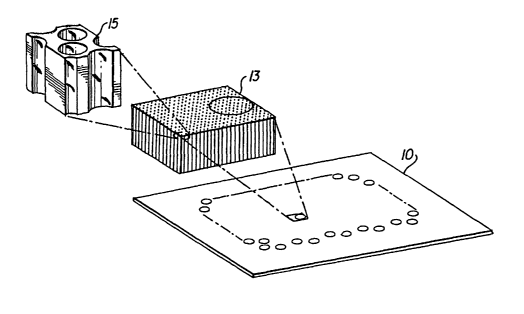
The FTC, which is a recent development, is a flow-through device that
comprises a
substrate containing first and second sides or surfaces, having a multiplicity
of discrete
channels extending through the substrate from the first side to the second
side. A
s schematic example of the FTC is shown in Fig. 1. The FTC 10 includes an
ordered
array of microscopic channels 13, such as channel 15 shown in greater detail,
that
transverse the thickness of the substrate. The FTC is particularly useful in
that arrays of
binding reagents, such as oligonucleotide probes, nucleic acids, and/or
antibodies can
be immobilized in the channels of the FTC, in spots that incorporate several
to microchannels. The term "probe" is used to describe a species immobilized
withiri the
microchannels and has some specific interaction with a "target" that is part
of the fluid
test mixture.
A major advantage of the FTCs is the uniformity of the array of microchannels
and the
is uniformity of the individual microchannels. This characteristic
distinguishes the
FTCs from other three-dimensional arrays, such as porous aluminum oxide, which
utilizes non-uniform hole sizes (and thus variable surface areas) and prevents
straightforward normalization of results.
2o The FTC design allows multiple determinations to be carried out in
parallel. U. S. Patent
No. 5,843,767, the entire disclosure of which is incorporated herein by
reference,
describes a microfabricated apparatus for conducting a multiplicity of
individual and
simultaneous binding reactions. The FTC design facilitates fluid flow
therethrough so
that biological recognition can occur within the confined volumes of the
microchannels.
2s The FTC can also be used in a variety of ways, such as a microreactor,
concentrator,
and micro-cuvette.
In practice, however, a conventional technique of holding and utilizing FTCs
has led to
several problems. For example, one technique of performing a hybridization
assay
3o utilizing the FTC entails placing the FTC on a small series of wells in a
vacuum
manifold, then placing the fluid test mixture onto the top surface thereof.
Vacuum
creates fluid flow. This technique, however, leads to substantial leakage
problems.
Another conventional technique entails placing the FTC in a container of fluid
and
2
CA 02468260 2004-05-20
WO 03/004162 PCT/US02/20607
relying on diffusion to create the fluid flow through the microchannels. While
initial
capillary action draws fluid into the microchannels, blockage problems can
quickly
decrease the flow rate. Further, utilizing this technique is disadvantageous
in that the
flow rate is not selectively controllable.
Some conventional gene chip array holders (or cartridges) are commercially
available.
For example, a gene chip array holder is available from AFFYMETRIX.
This gene chip array holder, however, operates with a non flow-through
substrate. In
io other words, this conventional cartridge does not facilitate uniform flow
during the
passage of fluid through the flow-through device. Therefore, this type of
conventional
design is inadequate to address fluid flow and leakage issues.
SUMMARY OF THE INVENTION
is The present invention relates to a chip holder, a cartridge embodying the
chip holder, a
system embodying the cartridge, and a method thereof.
The chip holder has a body, a flow surface, a test fluid chamber, and a first
port. The
body has a support that can support a flow though device, which has a first
side, a
2o second side, and an array of microchannel passages extending through the
first and
second sides. The flow surface is formed within the body and is adapted to
face the first
side (i. e., the flow surface faces the first side when the flow through
device is mounted).
The test fluid chamber can be defined at least by the flow surface and the
first side, and
is configured to produce a substantially uniform flow of a test fluid mixture
through the
zs microchannel passages. The first port communicates with the test fluid
chamber for
passing the test fluid mixture into the test fluid chamber.
The flow surface of the chip holder can be angled. The flow surface can
include a trench
that is sloped relative to the first side, from a first portion to a second
portion of the flow
3o surface, to provide a greater spacing at the first portion than at the
second portion from
the first side. The first port can be formed at the first portion and the
trench can have a
slope of about 1 to about 4 relative to the first side. More specifically, the
slope can be
about 2.55 relative to the first side.
CA 02468260 2004-05-20
WO 03/004162 PCT/US02/20607
The chip holder body further has a second port for draining the test fluid
mixture that
has passed through the flow through device. The chip holder support can
comprise a
first shelf disposed around the flow surface, with the support adapted to seat
a seal,
which can be sandwiched between the first side and the first shelf. The chip
holder body
can further include a second shelf disposed around the first shelf for seating
an
observation window.
Further, the chip holder body can include a recess formed on an opposite side
of the
flow surface. The recess can form a thermal chamber for controlling the
temperature of
to the test fluid in the test fluid chamber.
The cartridge according to the present invention can include a flow through
device, such
as the one described above, supported on the support, and a chip holder for
holding the
flow through device, such as the chip holder described previously. The flow
through
is device can be a FLOW-THRU-CHIP. The cartridge can further include a base
for
supporting the chip holder. The cartridge can also include a first seal
contactirig the first
side to prevent leakage of the test fluid in the test fluid chamber.
The first seal can contact a perimeter region of the flow through device on
the first side
2o to direct flow of the test fluid mixture through the flow through device
and can prevent
leakage of the test fluid mixture around the flow through device. The
cartridge can
include first and second seals in contact with perimeter regions of the first
and second
sides of the flow through device. to prevent leakage of the test fluid
mixture. The first and
second seals can be made of Viton rubber. The second seal can have a channel
to
2s direct a flow of the test fluid mixture to the second port.
The cartridge can include an observation window, which can be supported on the
body,
such as the second shelf, for viewing the second side of the flow through
device. The
window can be a low scatter window disposed over the second side of the flow
through
3o device. The cartridge can further include a cover with an opening
positioned over the
second side for passage of an optical signal therethrough. The cover, the
base, and the
chip holder all can be constructed from a metal coated with a low light
scattering
coating. Alternatively, the base, the chip holder, and the cover can be
injection molded
as one piece. The base can be coupled to the cover with a fastener.
CA 02468260 2004-05-20
WO 03/004162 PCT/US02/20607
The fastener can comprise a plurality of shoulder screws and spring washers.
The base
can have complementary threaded portions for receiving threaded portions of
the
shoulder screws. Alternatively, the fastener can comprise a latch, with the
cover and the
base hinged opposite the latch.
The base can. have a recess for receiving the chip holder. The recesses of the
body and
the base can form a thermal chamber for controlling the temperature of the
test fluid in
the test fluid chamber. The cartridge can further include an insert positioned
in the
io recesses to further define the thermal chamber. The insert can isolate the
thermal fluid
within the thermal chamber to prevent the test fluid from contamination. The
recess of
the base can be complementary to a low-end portion of the chip holder. The
cartridge
can also include means for distributing a thermal fluid into the thermal
chamber. The
cartridge can also include a fluid delivery mechanism for delivering the test
fluid mixture
is through the first port.
The system for performing hybridization assays according to the present
invention can
include the cartridge described previously and a fluidics station for
delivering the test
fluid mixture to the cartridge. The system can also include a temperature
controller for
2o controlling the temperature of the test fluid in the test fluid chamber.
The fluidics station
can comprise a pump for moving fluid through a fluid path, a buffer selection
valve for
controlling a passage of buffer solutions from buffer reservoirs, a sample
injection valve
for controlling the passage of a target or probe compound into the fluid path
to form the
test fluid mixture, and a re-circulation control valve in the fluid path and
communicating
2s with the buffer selection valve for controlling fluid flow. The re-
circulation valve can be
switched between an open circuit mode and a closed circuit mode. In the open
circuit
mode, the pump communicates with one or more of the buffer solutions to direct
the
buffer solutions through the sample injection valve and the cartridge. In the
closed
circuit mode, the pump flows the test fluid flow through the sample injection
valve and
3o the cartridge in a closed loop. The system can further include a system
controller for
monitoring and controlling fluid delivery, timing, and temperature of the
system.
The method of performing a hybridization assay according to the present
invention
comprises the steps of controlling a passage of buffer solution from a buffer
reservoir
CA 02468260 2004-05-20
WO 03/004162 PCT/US02/20607
into the chip cartridge, such as the ones described above, controlling the
passage of a
target or probe compound into the buffer solution to form the test fluid
mixture, and
circulating the test fluid mixture to the cartridge in a closed loop.
s BRIEF DESCRIPTION OF THE DRAWINGS
These and other.features, aspects, and advantages of the present invention
will
become more apparent from the following description, appended claims, and
accompanying exemplary embodiments shown in the drawings, which are briefly
described below.
io
Fig. 1 show a schematic representation of a conventional FTC.
Fig. 2 shows a schematic diagram of an automated hybridization assay system.
is Fig. 3 shows an exploded detailed view of an exemplary embodiment of an FTC
cartridge.
Figs. 4A-4G show detailed views of an FTC holder incorporated in the FTC
cartridge of
Fig. 3.
Figs. 5A-5C show detailed cross-sectional views of the assembled FTC cartridge
of Fig.
3.
Figs. 6A-6D show alternative embodiments of seals usable in the FTC cartridge
of Fig.
2s 3.
Fig. 7 shows another embodiment of an FTC.
Fig. 8 shows an FTC image illustrating non-uniform fluid flow using a flat-
back flow cell.
Fig. 9 shows an FTC image illustrating substantially uniform fluid flow using
a flow cell.
Fig. 10 shows a chart illustrating the effects of reflective and non-
reflective flow cell
surfaces.
6.
CA 02468260 2004-05-20
WO 03/004162 PCT/US02/20607
Fig. 11 shows a schematic view of a fluidics station for delivery of fluid to
the
FTC cartridge of Fig. 3.
s Fig. 12 shows an image taken of a hybridization assay illustrating the
uniformity of
hybridization using the FTC cartridge of Fig. 3. .
Fig. 13 shows a plot of FTC signal as a function of hybridization temperature.
to Fig. 14 shows images from the FTC reusability experiment.
Fig. 15 shows image results for each set of hybridization experiments
comparing a first
test cartridge design and a second test cartridge having a flat-back design
and multiple
inlets and outlets.
Fig. 16 shows a plot of hybridization signal versus time.
Fig. 17A shows an alternative flow surface of the test fluid chamber.
2o Fig. 17B schematically illustrates a fluid flow diagram of the flow surface
of Fig. 17A.
Fig. 18A shows another alternative flow surface of the FTC test fluid chamber.
Fig. 18B schematically illustrates a fluid flow diagram of the surface of Fig.
18A.
Fig. 19 shows an alternative fluidics station that can reverse the flow
through the FTC
cartridge.
Fig. 20A shows a front view of an alternative embodiment of the cartridge of
the
invention.
Fig. 20B shows a side view of an adaptor plate.
Fig. 20C shows a side view of elements of the cartridge shown in Fig 20A.
7
CA 02468260 2004-05-20
WO 03/004162 PCT/US02/20607
Fig. 20D shows a top view of a chip holder.
Fig. 20E shows a cross sectional view along section line A of Fig 20D.
s
Fig. 20F shows a cross sectional view along section line B of Fig 20D.
Fig. 20G shows a cross sectional view along section line C of Fig 20D.
io Fig. 21A shows a fluidics station for use with the cartridge shown in Fig
20A.
Fig. 21 B shows an alternative fluidics station having a single manifold.
Fig. 22A shows an alternative cartridge embodiment having a port.
is
Fig. 22B shows a cross sectional view along section line A of Fig 22A.
Fig. 22C shows a cross sectional view along section line B of Fig 22A.
2o Fig. 22D shows a cross sectional view along section line C of Fig 22A.
DETAILED DESCRIPTION
Fig. 2 shows a schematic diagram of an automated hybridization assay system
200,
zs which uses an FTC cartridge 210/300. The assay system 200 further includes
a test
fluid delivery system 220, an environment control unit 230, a detection system
240, and
a system controller 250.
The FTC cartridge 210 has one side of an FTC 215 facing an internal test fluid
chamber
30 211, which is designed to provide a uniform flow of a test fluid mixture
through the
microchannels of the FTC 215. The FTC cartridge 210 also includes a port
assembly
223 for communicating test fluid mixtures to and from the FTC 215 and the test
fluid
delivery system 220, such as the fluidics station illustrated in Fig. 11. The
FTC cartridge 210 can further include a temperature control chamber 213 to
control the
s
CA 02468260 2004-05-20
WO 03/004162 PCT/US02/20607
temperature of the test fluid mixture in the test fluid chamber 211 by heat
transfer.
Temperature control during hybridization provides advantages for nucleic acid
analyses,
as would be understood by those of skill in the art. Temperature control
chamber 213
can be coupled to the environment control unit 230, which can monitor and
alter the
environmental conditions in the test fluid chamber 211.
The FTC cartridge 210 can also include a sealing mechanism 225 that minimizes
test
fluid leakage and maximizes fluid flow through the FTC's microchannels.
Further, the
io FTC cartridge 210 includes a window 217 to permit in situ observation from
a detection
system 240, which can include real-time detection. Real-time hybridization
detection
can be useful for assay optimization, DNA melting studies, and kinetics-based
gene
expression analysis.
is The system controller 250, coupled to the test fluid delivery system 220,
the detection
system 240, and the environmental control system 230, can control and monitor
a
hybridization assay. The detection system 240 can include microfabricated
optical and
electronic detection components, film devices, charge-coupled-device arrays,
camera
systems, and phosphor storage devices that are known in the art. The test
fluid delivery
2o system 220, which can be, for example, a fluidics station 800 shown in Fig.
11, includes
a pump and one or more valves coupled to buffers and test fluid mixtures that
provide a
controlled flow of a test fluid mixture to the FTC cartridge 210.
In addition, the test fluid delivery system 220 can be further designed to
circulate pretest
2s and post-test cleansing fluids for multiple assay applications.
Advantageously, the flow
through devices can be reused in the FTC cartridge 210 according to the
present
invention.
The system controller 250 can include a microprocessor or computer that is
3o programmed with software, such as Lab-View (available from National
Instruments,
Austin, TX) that can control one or more of the systems described above. With
the
control system of the present invention, flow rates, buffer selection,
temperature, and
timing for one or more FTCs can be controlled independently. These components
will
be described in detail below.
CA 02468260 2004-05-20
WO 03/004162 PCT/US02/20607
Fig. 3 shows an exploded detailed view of the FTC cartridge 300 that can be
used with
the system of Fig. 2. The FTC cartridge 300 can include a base or bottom piece
310, a
chip holder 320, an FTC 330, sealing seals or seals 331,333,334, a window 340,
and a
s cover 350. The base, 310, chip holder 320, and/or cover 350 can be made from
a wide
variety of solid materials, such as metals, semi-metals, composites, plastics,
and
injection-molded materials. In the embodiment shown in Fig. 3, the structural
components of the FTC cartridge 300, namely the base 310, chip holder 320, and
cover
350, can be constructed from anodized aluminum. Alternatively, these
components can
io also be formed as a single construction, such as by conventional injection
molding, as
will be apparent to one of skill in the art given the present description.
Fig. 7 discloses
an embodiment of the FTC cartridge formed as a single piece.
The base 310 can include passages for a flow control system (described in
detail below
is in conjunction with the description of Fig. 7), such as a two pin/septa
system (via an
inlet 308 and an outlet 309). The flow delivery system, such as the pin/septa
system,
allows flow control of the test fluid mixture used in an assay. The base 310
can include
additional pin/septa as needed. The base 310 can further include an alignment
indicia
or tool, such as a bevel 312 to ensure that the FTC cartridge 315 is properly
assembled
2o with a fluid control system, such as the fluidics station of Fig. 11,
thereby reducing user
assembly error. The base 310 can further include a recess 311, which is used
to hold or
contain a thermal fluid. The thermal fluid can be delivered to the FTC
cartridge 300 via a
fluid delivery mechanism, such as the pin delivery mechanism shown in Fig. 7.
The
thermal fluid is ultimately used to provide for the temperature control of the
FTC. In
2s particular, the thermal fluid is used to control the temperature of the
test fluid mixture
(also referred to as target solution) around the FTC, while the assay is
running and
while the test fluid mixture is flowing through the FTC. Example thermal
fluids include,
but are not limited to, water and aqueous solutions of ethylene glycol and the
like.
3o An insert 313, such as a thermal seal, can be used to further control and
localize the
thermal fluid delivered to the FTC cartridge 300. The insert 313 can be formed
from
compressible materials such as CHR silicone, Volara, Poron, Minicell EPOM and
the
like. Alternatively, rubber, Viton, silicone, Buna-N, Neoprene rubber, and the
like, can
also be used. Moreover, the base 310 can be designed to include a set of walls
or
io
CA 02468260 2004-05-20
WO 03/004162 PCT/US02/20607
boundaries, i. e., a recess forming a chamber 311, to localize the containment
of
thermal fluid. The insert 313 is designed to isolate the thermal fluid from
contact with
(and subsequent contamination of) the test fluid mixture delivered to the FTC
cartridge
300. The insert 313 defines a thermal chamber 314 formed at the bottom side of
chip
holder 320. That is, the insert 313 forms a closed thermal chamber 314 that is
isolated
from the test (or process) fluid loop. The thermal fluid chamber 314 can be
coupled to a
temperature controller, such as environmental control system 230 shown in Fig.
2.
For example, an external temperature controller, such as a conventional fluid
bath and
io pump system, can deliver temperature controlled fluid to the thermal
chamber 314 to
heat or cool the test fluid chamber (discussed below), to facilitate
temperature controlled
hybridizations. Alternatively, the thermal chamber 314 can be substituted with
a closed
and controlled environmental chamber in which the fluid lines and the
FTC cartridge are enclosed. Alternatively, the thermal chamber 314 can be
designed to
is house an alternative temperature-controlling device, such as a thermo-
electric
heating/cooling device or a Pettier heating/cooling device, thereby
eliminating the need
for a thermal fluid delivery system. The alternative temperature-controlling
element can
be integrated into the FTC cartridge 300 or into a stage that accepts the FTC
cartridge
300.
The base 310 can further include one or more additional recesses 318 that are
designed to accurately position septa 317, through which the pins/needles
(708,709)
that deliver the test fluid mixture pierces. Similarly, additional septa 315
can be used to
accept pins/needles (717,718) that deliver the thermal fluid. See Fig. 7.
The base 310 can further include mounting holes, such as hole 319, which can
be
adopted to secure fasteners, such as screws or clips, that secure the cover
350 to the
base 310. Alternatively, the FTC cartridge 300 can be designed as a single
construction
(Fig. 7), thus obviating the need for such fasteners and mounting holes.
The chip holder 320 is designed to hold a flow-through device, such as an FTC
330,
during an assay. The FTC 330 is schematically illustrated as a square
structure, but can
be rectangle, circular, or have other polygonal shape. The chip holder 320 can
provide
other functions, such as housing the thermal chamber 314 and providing a test
fluid (or
n
CA 02468260 2004-05-20
WO 03/004162 PCT/US02/20607
process) chamber. The chip holder 320 is designed to provide a uniform flow of
test
fluid through the FTC 330. Seals can be used with the chip holder 320
minimizes
leakage of thermal and test fluids. Also, the chip holder 320 can support the
observation
window 340, as well as minimize scattering effects that can cause spurious
optical
signals during an assay. One method of reducing potential scattering effects
is to coat
the chip holder (as well as the other components of the FTC cartridge) with a
flat black,
low light reflecting, reduced scatter coating. This low light scatter coating
helps reduce
the amount of background light (signal) present during imaging.
to Indeed, a test performed comparing the relative background noise for a
reflective
coated chip holder (polished aluminum) versus a non-reflective coated chip
holder
(anodized aluminum) confirms the scattered light reduction. In particular,
Fig. 10 shows
the effects of reflective and non-reflective flow cell surfaces on image
background pixel
intensity. The left side of the graph (having a reflective flow cell back
surface) shows a
is much higher background signal noise (by about 20 arbitrary pixel units)
than the right
side of the graph, which corresponds to the background signal of the flow cell
having a
black/anodized coated back surface.
Detailed views of the chip holder 320 are shown in Figs. 4A-4G. Fig. 4A shows
the side
2o view of the chip holder 320. The chip holder 320 comprises a body with an
outer ridge
405 and a substantially hollow member 405H extending upwardly from the outer
ridge
405. The ridge 405 is contoured to snuggly seat into the recess 311 formed in
the base
310. A bevel in one of the corners can be used to ensure proper alignment
within the
base 310. Again, the shape of the chip holder 320 and the outer ridge 405 can
have
2s different shapes, depending on the contours of the base 310. The chip
holder 320 can
be manufactured from anodized aluminum. The anodized or black coating can be
used
to reduce light scattering effects produced during optical-based assays.
Alternatively,
the chip.holder 320 can be made from plastics, metals, semimetals, silicon-
based
materials, or injection-molded plastics. Further, the chip holder 320 and the
base 310
3o can be formed as a single unit, and even monolithically.
Referring to Fig. 4C, the underside of the chip holder 320 can include a
recess 414,
which defines an upper portion of the thermal chamber 213. Thus, the upper and
lower
chambers 414 and 314 both define the thermal fluid chamber 213 (in Fig. 2 or
451 in
12
CA 02468260 2004-05-20
WO 03/004162 PCT/US02/20607
Fig. 5C), which is used to contain thermal fluid for temperature control of
the test fluid
mixture. The correspondence in shape of chambers 414 and 314 is important to
ensure
that the thermal fluid is confined and not mix with the test fluid mixture. In
addition, the
depth of the recessed portion 414 (which corresponds to the distance between
the
upper surface 413 of the thermal fluid chamber and the flow surface 421,
discussed
below) can be optimized to ensure efficient heat transfer between the thermal
fluid
chamber 213 and the test fluid chamber 211. The efficient' heat transfer
properties of the
FTC cartridge 300 of the present invention facilitate well-controlled assays
that
determine the effects of temperature changes on hybridizations.
to
Also included within the recessed portion 414 are ports 417,418 for
introducing and
draining the thermal fluid into the test fluid chamber 211: These ports
417,418 can be
positioned to correspond to the location of the thermal fluid pin/septa in the
base 310.
The ports 417,418 can further include one or more slots or channels 419, which
are
is used to distribute the thermal fluid flow and help to provide a uniform
temperature
distribution within the thermal chamber 213. As shown in Fig. 4C, the ports
417,418
each include three fluid flow slots 419. The bottom side 415 of chip holder
320 further
includes an entrance guide hole 408 and an exit guide hole 409, which
correspond in
location to the inlet 308 and the outlet 309 discussed above. Thus, a test
fluid mixture
Zo will enter into the test fluid chamber 211 via the inlet 308 and entrance
guide 408, and
exit the FTC cartridge via the exit guide hole 409 and the outlet 309.
Referring now to Figs. 4B and 4D-4G, another unique feature of the chip holder
320 lies
with the flow surface 421, which in turn defines the shape of the test (or
process) fluid
2s chamber or the flow cell (identified in Figs. 5B and 5C as chamber 461 ).
The test fluid
chamber 461 is defined, in part, by the flow surface 42'1 and the bottom side
or bottom
surface of the FTC 330. The surface 421 can include a single entrance hole 428
for
introducing a test fluid mixture into the test fluid chamber 461. The single
entrance hole
428 can be provided near one corner of the chip holder 320, such as
illustrated in Fig.
30 4D. The present inventors have found that a single entrance hole located in
a corner
region is advantageous over other entrance port schemes (e. g., ports from the
perimeter of the FTC where fluid flows parallel and perpendicular to the sides
of the
FTC). Alternatively, multiple inlets and outlets from the chip holder (as well
as from
other components of the FTC cartridge can also be employed to distribute the
fluid more
13
CA 02468260 2004-05-20
WO 03/004162 PCT/US02/20607
uniformly across the FTC 330.
According to an aspect of the present invention, the flow surface 421 is
deliberately
angled so that it has a spade-or shovel-like shape that changes in elevation
relative
s from one corner to the opposite corner. Referring to Figs. 4D, 4E, and 4G,
the lower
elevational end is adjacent to the entrance hole 428 and higher elevational
ends are
located at an opposite corner portion 427 and corner portions 424 and 425. A
first slope
along the diagonal (a,) is shown in Fig. 4E, where the relative elevation of
the flow
surface 421 varies from the entrance hole 428 to the opposite corner portion
427.
to
The slope angle a I can range from about 1 to about 20 , more preferably
between about
1 to about 4 . A slope angle of about 2.55 is most preferred. A second slope
angle (a2)
is measured from entrance hole 428 to corner portions 424 or 425. Fig. 4G
shows the
second slope angle a2 as measured from the entrance port 428 to corner portion
424.
is The second slope angle can range from about 1 to about 20 , more preferably
between
about 1 to about 5 . A slope angle a2 of about 3.7 is most preferred. But
these slope
angles can be varied, depending on various factors, such as fluid viscosity,
fluid force,
and the degree of uniformity of flow required for a particular assay: In
addition, the slope
of the flow surface 421 can be further varied depending on the number of test
fluid
2o entrance points used and the uniformity of flow required for an assay.
The spade or shovel-like shape of the flow surface 421 is further illustrated
in
Fig. 4F, which shows a side view of the flow surface 421 from the perspective
of the
entrance hole 428. As shown in Fig. 4F, the flow surface 421 includes a trench
(i. e.,
2s V-shaped) that is defined by its lowest and highest relative points along
line 426 (Fig.
4D) at the opposite corners, at the corner portion 427, and the opposite sides
or corner
portions 424 and 425 having the highest point relative to the trench along the
line 426.
In the rectangular/square configuration shown in Figs 4A-4G, the length of
trench line
30 426 is along the diagonal of flow surface 421. Thus, the trench angle can
vary along the
length of the trench line 426. As shown in Fig. 4F, the trench angle ss is
measured at a
midpoint of line 426. In this regard, the angle of the trench can be between
about 0.5 to
about 12 , or about 1 to about 5 . A trench angle B of about 2.6 is most
preferred. Of
course, the trench angle B of the flow surface 421 can be varied depending on
the
14
CA 02468260 2004-05-20
WO 03/004162 PCT/US02/20607
number of test fluid entrance points used and by the degree of uniform flow
required for
a particular assay. The chip holder 320 also can employ a bowl-back design for
its test
fluid chamber, as described in more detail below.
s The spade-like shape of the flow surface 421 is used to equalize fluid
pressure moving
across the two-dimensional geometric area of the FTC. As fluid flows from the
source of
fluid pressure (i. e., entrance 428), the slope maintains the backpressure at
the base of
the chip holder. This shape forces fluid into a constantly decreasing volume
beneath the
FTC as it moves from the fluid pressure source.
io
The importance of the uniformity of flow can be further illustrated in
relation to
experiments performed by the inventors, the results of which are shown in
Figs. 8 and
9, as well as discussed in Experiment 4 below. Fig. 8 shows a fluorescent
microscope
image of flow in a multi-port, flat-back flow cell, with the flow rate being
approximately
is 0.2 milliliters per minute (ml/min.). This image shows multiple bright and
dark image
regions, indicating different flow rates in different areas of the FTC being
images. Fig. 9,
on the other hand, shows a fluorescent microscope image of flow in a single-
port, flow
cell having a spade-like surface, similar to the embodiment described above.
Both
images were taken after an identical period of elapsed time. The image shown
in Fig. 9
2o shows a much more uniform flow through the FTC, as indicated by the
substantially
uniform image intensity across the FTC. The results of a comparison between
the two
figures show that the test fluid chamber having a spadelike configuration,
such as a V-
shaped cross-sectional profile, greatly enhances the uniformity of flow.
2s Referring back to Figs. 4B and 4D, a series of shelves or lips 431,432 can
be designed
within the substantially hollow member 405H to support the FTC 330, the
observation
window 340, and/or one or more seals. This arrangement allows use of seals to
minimize leakage of a test (i. e., process) fluid mixture. For example, in
Figs.4D and 5A,
a lower shelf 431 extends inwardly from the member 405H and around the
periphery of
3o the flow surface 421. A lower seal 331 (Fig. 5) is sandwiched between the
shelf 431 and
the lower side of the FTC 330. The shelf 431 allows the lower seal 331 to be
disposed
within the chip holder 320 in a level manner, as shown in more detail in
Fig. 5A, to allow the FTC 330 to be at level. The design of the shelf 431 can
vary
depending on the type of seal used.
is
CA 02468260 2004-05-20
WO 03/004162 PCT/US02/20607
As mentioned, the FTC 330 is placed over the lower seal 331, which provides a
cushioned support for the FTC and helps reduce leakage around the sides of the
FTC,
thus ensuring that test fluid will flow from the test fluid chamber through
the FTC. As
s shown in Figs. 4D and 5A, the chip holder also includes an upper shelf 432
extending
inwardly from the member 405H. The upper shelf 432 is designed to allow a snug
placement of an upper seal or seals 333,334, on top of the FTC 330. In
addition, the
upper shelf 432 further includes an exit hole 429, which directs test (or
process) fluid
that has passed through the FTC to the exit guide hole 409 and out of the FTC
cartridge
l0 300. The perimeter of the upper shelf 432 is designed to conform to the
shape of the
upper seal (s) to prevent leakage of the test (or process) fluid around the
FTC 330. The
height of the upper shelf 432 can be designed such that the lower side of the
upper seal
334 contacts the perimeter region of the FTC 300. The chip holder 320 can
further
include an upper ridge 433, which is designed to conform to the shape of the
is observation window that is disposed on an upper surface of the upper seal
(s) 333,334,
which can be a single seal, as shown in Fig. 6B.
The single upper seal 335 further includes a hole 336 and a slot or channel
337. The
location of hole 336 corresponds to the location of the exit hole 429 (Fig.
4D), which
2o directs test (or process) fluid that has passed through the FTC to the exit
guide hole 409
and out of the FTC cartridge. The slot 337 in turn further directs the flow of
test fluid that
emerges from the microchannels of the FTC into the hole 336. In addition, the
upper
seal can be designed to have inner perimeter rounded corners to help enhance
the
wetting properties of the FTC cartridge. The lower seal 331 and upper seal 335
are
2s designed to maximize the active area ofthe FTC (i. e., the area where flow
is allowed to
pass through the microchannels of the FTC). The upper and lower seals can
cover a 1-
millimeter wide perimeter on the FTC. Other seal designs for directing fluid
flow will be
apparent to those of skill in the art given the present description.
3o An alternative seal 338 is shown in Fig. 6C. The seal 338 is designed to
provide for a
smaller active area for the FTC. This design allows an experimenter to
localize
or"focus"a test fluid, such as a target solution, on a particular region of
the
FTC. The seal 338 can further include a hole 336 and a fluid flow channel 339,
similar to
those of Fig. 6B.
16
CA 02468260 2004-05-20
WO 03/004162 PCT/US02/20607
Another alternative upper seal 345 (Fig. 6D) has more than one opening, thus
providing
for multiple active areas. Test fluid can then only flow through particular
regions of the
FTC. A bottom seal (not shown) of similar design can be employed, thus
creating a
series of tunnels, to further direct fluid flow through only particular
regions of the FTC. In
another alternative embodiment, the seals 331 and 335 can be formed as a
single seal
that surrounds a perimeter region of the FTC. For example, a single shrink-
wrapped
seal can be placed around the perimeter of the FTC then treated to form fit
upper and
lower portions around the perimeter of the FTC.
io
The seals reduce leakage of the test fluid flowing through the FTC 330. In
addition, the
seals further ensure proper test fluid flow through the FTC and back into the
fluid
delivery mechanism, as opposed to an alternative path around the perimeter of
the
FTC. Further, the seals reduce the number of metal/glass contact points that
could
is potentially damage the FTC. The upper and lower seals of the present
invention can be
formed from any material commonly used in sealing applications. For example,
the
seals can be formed from rubber, Viton, silicone, Buna-N, Neoprene rubber, and
the
like. In a preferred embodiment, the upper and lower seals are Viton rubber.
Viton is
advantageous in that it is non-fluorescent, it maintains its shape over many
uses, and it
2o does not react with or promote analyte binding to its surface.
Referring back to Fig. 3, the FTC 330 can include any flow through device that
includes
a substrate containing a first and second surface, where the channels extend
through
the substrate from the first to the second surface. Suitable substrate
materials include
2s microchannel or nanochannel glass and porous silicon, which can be produced
using
known microfabrication techniques.
The in situ observation window 340 can be designed to be disposed on the upper
seal
334 and snugly fit inside the upper ridge 433 of the chip holder 320. See Fig.
5A. The
3o window 340 can be formed from a variety of materials including, but not
limited to, glass
(doped and undoped), quartz, or any other transparent material that does not
interfere
with the signal of interest emanating from the FTC. In addition, window 340
can be
made from wavelength-specific filter glass that selectively transmits incident
and exiting
light, such as at the emission and excitation wavelengths of a fluorophore
being used in
17
CA 02468260 2004-05-20
WO 03/004162 PCT/US02/20607
a FTC experiment. In a preferred embodiment, window 340 includes borosilicate
glass,
which is advantageous because it costs low and minimally interferes with the
fluorescence microscopy used to image FTCs. The window 340 allows
visualization of a
FTC reaction in real time under a fluorescence microscope, for those
experiments
where an analyte to be detected is pre-labeled with a light emitting reporter
molecule.
The window 340 can have a thickness of about 1 mm or less and can be disposed
at a
distance of about 1 mm from the top of the FTC. The inventors have discovered
that a
window thicker than 1 mm tend to absorb and scatter more light, thereby
reducing light
to collection efficiency. Accordingly, the thickness of the glass can be
selected according
to the type of glass used and the light collection efficiency desired. In
alternative
embodiments, the chip holder can be designed such that the distance between
the
bottom surface of the window and the top surface of the FTC is minimized to
reduce
potential scattering, while taking into account fluid flow considerations.
As shown in Figs. 5A and 5C, the window 340 can be held in place by a cover
350 to
provide a uniform cartridge compression of the sealing seals around the
perimeter of
the FTC. As with the other components of the FTC cartridge 300, -the cover 350
can be
made of any of the structural materials mentioned above. In a preferred
embodiment,
2o the cover 350 is constructed of anodized aluminum.
As shown in Figs. 3 and 5A, the cover plate 350 includes an opening 351 that
allows the
passage of light to and from the FTC. Recessed holes, such as a hole 355, are
provided
to guide the compression/fastening devices, such as a screw 352 and a washer
353, to
2s their proper locations to fasten the cover 350 onto the base 310. For
example, four
shoulder screws and corresponding spring washers can be used to uniformly
compress
the FTC cartridge. More specifically, shoulder screws can be used to set the
distance
between the top and bottom cartridge components. The spring washers compress
the
top and bottom cartridge pieces with a controlled force equal to the additive
force of all
3o four springs. This significantly enhances cartridge loading reproducibility
and control
over designs using fewer screws or fasteners.
In an alternative embodiment shown in Fig. 7, the aluminum FTC cartridge
material can
be substituted with injection molded parts that snap together to form a
uniform and
is
CA 02468260 2004-05-20
WO 03/004162 PCT/US02/20607
reproducible seal. For example, an FTC cartridge 720 (having a FTC, a thermal
chamber, a test fluid chamber, and a sealing subsystem, similar to those
described
previously) can be integrally formed with a top cover 750 that is either
formed into or
placed in cartridge casing 760, for example by sliding along a track 765. A
latch or snap
s fitting 770 can be disposed on the cartridge casing or on the fluid delivery
stage 780 to
which the FTC cartridge interfaces to provide a sealing of the fluid delivery
pins/needles
with the FTC cartridge.
Figs. 17A and 18A show alternative embodiments of the flow surface of the
to FTC test fluid chamber. Other alternative structures will be apparent to
those of skill in
the art given the present description.
Fig. 17A shows a flow surface 1021, the FTC 330, and the window 340. The
FTC 330 and the window 340 have been described above. The flow surface 1021
has
is an entrance port 1028 located at its central region. The flow surface 1021
slopes
upwardly and outwardly (as shown in Fig. 17A) toward the periphery of the FTC
330,
such as perimeter edges 1031 and 1032. As shown in Fig. 17A, the flow surface
1021
includes multiple trenches (i. e., V-shaped channels) 1026a, 1026b, and 1026c,
to form
a pyramid-configuration. The slope of the trenches (as measured from the
entrance port
2o to the perimeter) can have any practical slope, from about 0.5 to about 12
, desirably
between about 1 to about 5 . Of course, the number of trenches, entrance
ports, and the
slope of the trenches of the flow surface 1021 can be varied depending on the
degree of
uniform flow required for a particular assay.
2s The flow direction of the flow surface 1021 is shown in Fig. 17B. The solid
arrows 1040
illustrates test fluid flow underneath the FTC. In this embodiment, four
diagonally
configured sloped trenches (i. e., 1026a, et seq.) can be utilized to produce
the type of
test fluid flow shown in Fig. 17B. The dashed arrow represents the test fluid
flow above
the FTC and beneath the window. For example, this fluid flow above
3o FTC 330 can be produced utilizing a single upper seal, such as the seal 335
shown
above in Fig. 6B, which includes the hole 336 and the slot or channel 337 to
direct fluid
flow away from the FTC.
The embodiment of Fig. 18A also has a flow surface 1121 with an entrance port
1128
19
CA 02468260 2004-05-20
WO 03/004162 PCT/US02/20607
located centrally of the flow surface 1021. The flow surtace 1121 curves
upward and
outwardly toward the periphery of the FTC 330, such as perimeter edges 1131
and
1132, forming a funnel configuration., which is devoid of trench like
structures. Of
course, the curvature of the flow surface 1121 can be varied depending on the
degree
s of uniform flow required for a particular assay.
The flow direction of flow surface 1121 is shown in Fig. 18B. The solid arrows
1140
illustrates test fluid flow underneath the FTC. In this embodiment, the flow
surface
provides a substantially uniform flow distribution toward the perimeter. The
dashed
io arrow represents the test fluid flow above the FTC and beneath the window.
For example, this fluid flow above FTC 330 also can be produced utilizing a
single
upper seal, such as the seal 335 shown above in Fig. 6B, which includes the
hole 336
and the slot or channel 337 to direct fluid flow away from the FTC. A seal
with multiple
is exit channels can also be utilized as would be apparent to one of skill in
the art given
the present description.
Referring now to Fig. 7, a test fluid mixture can be delivered to the FTC via
a test fluid
delivery mechanism or assembly 723. The assembly 723 can include one or more
fluid
20 delivery pins/needles that are coupled to a fluidics station, such as the
one illustrated in
Fig. 11. The assembly includes an inlet pin 708 and an outlet pin 709 to
provide a
closed loop fluid circulation. Optionally, vacuum seals, such as a vacuum seal
713 or
septa, can be used to prevent leakage and contamination of the test fluid
mixture. In
addition, if thermal fluid is being delivered to the thermal fluid chamber
213, separate
2s inlet and outlet pins 717 and 718 can be used. In addition, septa for each
of the pins
can be provided in the FTC cartridge, as discussed previously. Alternatively,
a single
septum can be used as opposed to four separate septa.
A pin/septa-based fluid delivery system can be used for the interface between
the
3o fluidics station and the FTC cartridge because these components are re-
useable. They
allow a user to remove and replace cartridges from the fluid delivery system
without
introducing air bubbles. Factors to consider in the use of specific pin/septa
systems
include (1 ) if the pin is too small, there can be an undesirable coring of
the septa and (2)
if the pin is too large, the risk of leakage increases. For example, pins
having holes to
CA 02468260 2004-05-20
WO 03/004162 PCT/US02/20607
the side (see e. g., Fig. 7) can be used to deliver the test fluid. Such a pin
design can
reduce the probability of orifice occlusion. Septa materials such as silicone-
based
materials, PTFE, Viton, and the like can be used.
s According to another aspect of the present invention, the FTC cartridge 300
can be in
fluid communication with a fluidics station that facilitates target re-
circulation through the
FTC. Fig. 11 shows an example fluidics station 800 that can be used with the
FTC
cartridge 300 according to the present invention. In this embodiment, the
fluidics station
800 can include three valves: a buffer selection valve 805, a recirculation
control valve
l0 807, and a sample injection valve 811. The fluidics station 800 can further
includes a
peristaltic pump 809, and an FTC cartridge, such as the FTC cartridge 300
shown in
Figs. 3-5. Fluids can communicate through these elements in a circular loop
through a
fluid path P.
is In operation of the fluidics station 800, the re-circulation valve 807
switches between an
open circuit mode or position and a closed circuit mode or position. In the
open circuit
mode, the valve 807 directs buffer fluids from the buffer reservoirs 803 into
the fluid path
P, into the pump 809, into the FTC cartridge 300, and back to .the valve 807,
which
directs flow to waste. The open circuit mode can be used to wash the
2o FTC cartridge, as well as for pre-and post-preparation of a hybridization
process. During
the open circuit mode, a test sample fluid is loaded into the sample injection
valve 811,
which is isolated from communication with the open circuit of flow path. In
order to begin
a hybridization (after the fluid line P and the cartridge 300 have been filled
with fluid, e.
g., buffers), the valve 807 can be switched to the closed circuit mode. In the
closed
2s circuit mode, the valve 807 closes communication with the buffer reservoirs
803 and the
waste, so that the buffer flows in a closed loop through the pump 809, the FTC
cartridge
300, and back to the pump 809. Once a closed loop is achieved, the sample
injection
valve 811 (having been previously loaded with a test sample) is opened to
fluid
communication from the pump 809 and to the cartridge 300 such that fluid flow
from the
3o pump 809 is diverted through the sample injection valve 811 and to
cartridge 300. The
sample injection valve 811 is kept in the open position for the duration of
the
hybridization, and the reaction proceeds while the pump recirculates the test
sample
through the closed circuit for a designated period. The peristaltic pump 809
drives fluid
through a closed loop or path. The peristaltic pump 809 can be used because it
is cost
21
CA 02468260 2004-05-20
WO 03/004162 PCT/US02/20607
effective, it can be used as an external, non-invasive pumping system, it can
pump fluid
in a closed loop, and it can be easily configured to a large range of fluid
flow rates.
Alternatively, a cartridge-internal pump, such as a miniature peristaltic pump
or an
electrode-based pumping device can be used.
The fluidics station of the present invention in conjunction with the FTC
cartridge offers
an advantage over conventional assays in that the fluidics station and the
FTC cartridge facilitate multiple-pass target experiments. As the inventors
have
determined, a single pass of a target through an FTC can have limited
sensitivity, thus
to requiring some form of amplification of the signal to determine low
abundance targets.
Sensitivity can be enhanced or increased by passing the target (contained in
the test (or
process) fluid mixture) through the FTC more than one time.
In operation, a test fluid is delivered to the FTC cartridge by a fluid
delivery system,
is such as the fluidics station 800. The test fluid enters an entrance port,
such as the inlet
428 shown in Fig. 5B. The test fluid then flows into a test fluid delivery
chamber that is
designed to provide a substantially uniform flow through the FTC (e. g.,
chamber 461
shown in Figs. 5B and 5C). The fluid then passes up through the microchannels
of the
FTC. The seals prevent the fluid from flowing in other areas.
After passing through the FTC, test fluid is directed to an outlet, such as
the outlet hole
429 shown in Fig. 5B. The test fluid returns to the fluidics station where it
can be
recirculated or disposed of as waste. Thus, the FTC cartridge and the fluidics
station
according to the present invention can provide a system that directs the flow
of test (or.
2s process) fluid through a FTC in a controllable manner.
In addition, the fluidics station according to the embodiment of the present
invention
shown in Fig. 11 can include a system for the delivering and temperature
controlling of a
thermal fluid to the FTC cartridge. For example, the fluidics station 800
further include a
3o temperature control unit, such as a conventional water chiller unit or an
immersion
circulator, for controlling the temperature of the thermal fluid delivered to
the FTC
cartridge.
22
CA 02468260 2004-05-20
WO 03/004162 PCT/US02/20607
Alternatively, a fluidics station 1200 can also provide a reverse flow. Fig.
19 shows such
a fluidics station 1200, which can use a syringe pump 1208 to inject or
withdraw a test
sample through the FTC. The fluidics station 1200 includes a sample injection
valve
s 1211, a FTC cartridge 300, such as the ones described above, an
aspirate/dispense
valve 1206, the syringe pump 1208, a buffer selection valve 1205, and buffer
reservoirs
1203 and 1204 (additional buffer reservoirs can also be included).
Optionally, a waste solution reservoir 1220 can also be included having a
lengthy
io conduit in communication with the FTC cartridge 300. Other arrangements of
these
components than that is shown in Fig. 19 would be apparent to those of skill
in the art
given the present description.
For example, the fluidics station 1200 can operate as follows. In a
prehybridization
is routine, the syringe pump 1208 aspirates buffer from the buffer source
1203,1204 and
dispenses buffer into the cartridge 300 and out to the waste 1220.
During this routine, a test sample can be loaded into the sample injection
valve 1211,
which can be similar to or the same as same as sample injection valve 811
shown in
2o Fig. 11.
In a hybridization routine, the aspirate/dispense valve 1206 (which can be a
two position
valve) is placed in a cartridge/waste position. Also, the sample injection
valve 1211 is
opened to communicate with the syringe pump 1208 so that the syringe pump 1208
can
2s position a slug of the test sample inside the cartridge 300 containing the
FTC.
After positioning, the syringe pump 1208 can oscillate the test sample back
and forth
across the FTC for a designated period of time. The amount of test fluid that
flows into
and out of FTC cartridge 300 can be a very small volume for the hybridization
routine.
For example, in a forward flow direction, the syringe pump 1208 injects test
fluid into
cartridge 300. In a reverse flow direction, syringe pump 1208 withdraws test
fluid from
the cartridge 300, where excess test fluid can also be drawn through from the
fluid
conduit between FTC cartridge 300 and waste reservoir 1220.
23
CA 02468260 2004-05-20
WO 03/004162 PCT/US02/20607
In a post-hybridization routine, the syringe pump 1208 stops oscillating and
forces any
non-reacted test sample to waste. Then, the system can wash the FTC in the
same
manner as was done in pre-hybridization, after which imaging can take place on
a
separate piece of imaging equipment (not shown for simplicity).
Advantages of using an oscillation pumping scheme can include reduction of
total
hybridization volume (relative to a re-circulation technique) resulting in
higher test
sample concentration (which can drive the reaction faster). Also, an
oscillation pumping
io scheme can provide more efficient hybridization due to a greater number of
"passes"through the FTC per unit time. In this regard, because the test sample
can only
hybridize when inside the microchannels of the FTC, and because diffusion can
not
occur between microchannels, the rate of test sample hybridization can be
dependent
on the number of passes made through the FTC.
is
Alternative Flow-Thru Chip Cartridge, Alternative Chip Holder, and
Alternative Fluidics Station
In an alternative embodiment to the FTC cartridge described above, multiple
fluid
2o channels can be included in the FTC cartridge. In addition, an alternative
fluidics station
can be used. These alternative designs can be used for detecting biological
molecules.
Fig. 20A shows a front view of an alternative FTC cartridge 2000. Fig. 20C
shows a side view of the major components to the FTC cartridge 2000. Fig. 20B
shows
2s a side view of a mount or adapter plate 2050 used to couple FTC cartridge
2000 to a
fluidics station 2100 (see Fig. 21A). The FTC cartridge 2000 includes: a chip
holder
2002, a FTC 2004, and a cover 2008. The configuration of the chip holder 2002
is
discussed in more detail below. The FTC 2004 can be similar to or the same as
the FTC
330 described above. The cover 2008 can be a glass, plastic, or other suitable
material
3o that is transmissive to optical radiation at the test wavelengths) of
interest. The cover
2008 can be coupled to the chip holder base 2002 via an adhesive layer 2006,
such as
24
CA 02468260 2004-05-20
WO 03/004162 PCT/US02/20607
double sided medical grade adhesive tape (e.g., a thin film of medical grade
adhesive)
or the like.
Fig. 20D shows a top view of the chip holder 2002. With this design, the chip
holder 2002 is formed as part of (or integral with) a base structure 2010. For
example,
the chip holder can be formed (e.g. milled, machined, etched, etc.) out of a
solid
material, a metal (such as aluminum, brass, steel, or other metal) or,
preferably, the
chip holder can be formed in an injection molded plastic material or the like.
In addition,
the base structure 2010 can be formed from a hydrophobic material, or coated
with a
io hydrophobic coating, in order to prevent mixture of fluids at fluid channel
intersections,
such as portion 2027. Detailed cross-sectional views are shown in Figs. 20 E
(section
A), 20F (section B), and 20G (section C).
With the configuration shown in Figs. 20A-20G, one or more probe samples may
be dispensed into and carried directly on the cartridge before connection to a
fluidics
is station. As shown in Fig. 20D, this chip holder design further includes at
least one test
fluid port 2012, at least one waste port 2014, and at least one probe sample
port, e.g.,
2016 and 2018, each coupled to conduits emerging from the rear side of the
base 2010.
According to this embodiment of the invention, single or multiple ports can be
utilized for
the test fluid, the waste fluid, and the probe sample ports. In addition, test
fluid port
20 2012 is in fluid communication with test fluid channel 2013. Waste fluid
port 2014 is in
fluid communication with waste fluid channel 2015. Probe sample ports 2016 and
2018
are in fluid communication with probe sample channels 2017 and 2019,
respectively.
Channels 2013, 2015, 2017, and 2019 can be bounded by adhesive layer 2006 or
cover
2008. The structure of the channels can be straight, curved, thin, deep, wide,
or narrow,
2s depending on the type of assays to be performed. ,
The chip holder 2002 may include a ridge upon which the FTC 2004 can be
supported. The FTC can sit directly on ridge 2022 or on a gasket (not shown,
configured
to match the shape of the ridge 2022). For example, fluid from channel 2013
enters
chamber 2009 via port 2024.
CA 02468260 2004-05-20
WO 03/004162 PCT/US02/20607
According to a further alternative, as shown in Figs. 22A-22D, the alternative
FTC cartridge 2000 can also include an air release port 2034 in fluid
communication
with air release channel 2032 to release air bubbles formed within fluid
chamber 2009.
Air bubbles can then be released from chamber 2009 through port 2033.
Preferably,
port 2033 should be located proximate to the top corner of chamber 2009 so
that
bubbles rising to the comer are forced out the air release port 2033.
Channels 2013 and 2032 can be in fluid communication with the fluid chamber
2009 beneath the FTC 2004, between the lower cartridge body and the FTC. The
depth
io of chamber 2009 can be about a few thousandths of an inch to about 50
thousandths of
an inch (i.e. below the lower surface of the FTC). Channels 2015, 2017, and
2019 can
be in fluid communication with the chip holder 2002 at a position above the
FTC ,
between the printed FTC 2004 and the cover 2008. Upper and lower cartridge
bodies
define the boundaries for the fluid reservoirs, ports, and the chip chamber.
Further, the
is adhesive layer 2006 can include a cut out portion 2026 which provides fluid
flow to
and/or from the top surface of the FTC to channels 2015, 2017, and/or 2019.
Channels
2017, and/or 2019 can be configured to hold about 50,uL to about 100,uL.
FTC cartridge 2000 can be connected to the fluidics station 2100 (see Fig. 21
A)
2o via an adapter plate 2050 that positions incoming fluid lines to each
cartridge port, as
shown in Fig. 20B. The joint between each line and its corresponding port can
be
sealed by a compressible 0-ring, gasket, or the like.
The FTC cartridge 2000 described previously can be used in conjunction with a
2s syringe pump fluidics station 2100 that includes further features relative
to that which is
described above. Figure 21A illustrates a schematic diagram of the fluidics
station 2100.
First, a single syringe pump 2120 can be directly connected to multiple assay
selection
valves, each of which controls the flow between a single assay solution and
the pump
2120 such that an open assay solution valve connects the flow between the
assay
3o solution and the syringe pump only. The syringe pump 2120 can also be
directly
26
CA 02468260 2004-05-20
WO 03/004162 PCT/US02/20607
connected to the entry port 2012 of the cartridge 2000 from Figure 20D.
Alternatively, a
two position solenoid valve, not shown, can be placed between the syringe pump
and
the test fluid port 2012.
On the outlet side of the cartridge, each of the fluid reservoirs of the
cartridge are
directly connected to a set of sample selection valves 2140, each of which
controls the
flow between the fluid reservoirs) (e.g., 2013, 2015) and the waste container
2150 such
that an open sample selection valve connects fluid flow between the syringe
pump
2120, the chip chamber 2009, the fluid reservoir(s), and the waste container
2150. The
io valves are preferably two-position solenoid valves, although other valves
may be
utilized as would be apparent to one of ordinary skill in the art given the
present
description.
A further alternative to the fluidics station can be the incorporation of all
fluid lines
into a single manifold, such as shown in Fig. 21 B. This design drastically
reduces both
is the space required to house such a fluidics station 2100 as well as the
total volume
necessary for performing routine assays.
In an example assay, 60uL probe samples can be manually dispensed into the
channels 2017 and 20.19 designated as probe sample 1 and probe sample 2 in
Fig. 21A.
2o The cartridge 2000 can then be placed into the adapter plate 2050 located
on
(preferably) the front of the fluidics station 2100. The cartridge can then be
clamped in
place in order to create a leak free connection between the cartridge 2000 and
the
various adapter plate ports. Buffered saline can then be pumped through the
cartridge
to condition it by repeatedly aspirating fluid from an assay solution and
dispensing the
zs fluid through the chip chamber 2009 to the waste port. This process can
thoroughly wet
the entire chip and remove all air from the chip chamber 2009.
When an assay begins, all assay solution valves close, probe sample I
selection
valve can be opened, and the sample can be aspirated into the chip chamber,
and
30 oscillation of the syringe pump can begin. This process allows for the
maximizing of fluid
27
CA 02468260 2004-05-20
WO 03/004162 PCT/US02/20607
contact with the FTC. Additionally, temperature control can be provided via an
electric
heating pad or the like positioned on the adapter plate in close proximity to
the position
of the FTC. After reaction with probe sample 1 is complete, the probe sample 1
selection valve closes and the FTC is flushed as described for the
conditioning step.
s This process forces any non-reacted probe sample to waste. Reaction with
probe
sample 2 and any other probe sample/fluid reservoir follows the same process
as just
described for probe sample 1. Once the entire assay has been completed, the
FTC
cartridge can be taken to an imaging station designed to collect visual
information from
the reacted FTC. Alternatively, an imaging station can be directly mounted to
the fluidics
io station and visual information can be collected as would be apparent to one
of ordinary
skill in the art given the present description.
During the assay process, temperature control may be necessary. However,
increasing the temperature can cause heavy outgassing of the solution and
adhesive
is materials. Any air that becomes trapped in the vicinity of the array on the
FTC can void
the reaction. Thus, in a further alternative to the cartridge and fluidics
station design
described above, an additional port 2034 (see Fig. 22A) can be included so
that air
bubbles can be removed at or near the top comer of the chip chamber (near
position
2026 shown in Fig. 22A). The air bubble removal can be accomplished by closing
all
2o assay solution and sample selection valves, opening the air release valve
out to air or to
the waste container. This alternative embodiment can eliminate air bubbles in
the lower
chamber 2009 of the cartridge 2000. Bubbles in an upper chip fluid chamber
(formed
between the upper surface of FTC 2004 and the cover 2008) do not require such
a port
as they can be automatically forced to waste through the waste sample
selection valve.
The improvements and alternative embodiments described above to both cartridge
and
fluidics station may provide the following advantages: reduction of total
fluid volume and
physical space needed to run the fluidics station, elimination of cross-
contamination by
restricting the probe samples) to the cartridge and waste lines only,
reduction of
3o sample dilution by restricting the probe samples) to the cartridge and
waste lines only,
28
CA 02468260 2004-05-20
WO 03/004162 PCT/US02/20607
and enhancement of assay flexibility and complexity by including multiple
sample
reservoirs on the cartridge and controlling them by multiple solenoid valves
within the
fluidics station. A principle advantage of these alternative embodiments is
that the
reagents may be loaded directly into the cartridge rather than being loaded
into a valve
chamber that is external to the cartridge.
As mentioned above, a flow-through device, such as the FTC, can be used in the
FTC
cartridge of the present invention. While the FTC can be used in a wide
variety of
assays, provided below are illustrative examples of the features and
advantages of the
io FTC, and some of the types of assays in which FTC can be used.
For example, the FTC can be used as a"genosensor,"where the binding reagent is
an
oligonucleotide or polynucleic acid that is immobilized in the channels of the
substrate,
and in which the analyte is a nucleic acid that is detected by hybridization
(base pairing)
is to the binding reagent. Particular embodiments provide some or all of the
following
advantages (among others) over conventional devices for detecting binding
reactions:
(1 ) improved detection sensitivity due to the vastly increased surface area
of binding
reagent to which the analyte is exposed. This increased area is due to the
greater
surface area of the channel surfaces compared to conventional devices where
the
2o binding agent is restricted to the two-dimensional surface of the device.
The presence of
the binding reagent on the inner surface of the channels running through the
substrate
greatly increases the quantity of the binding reagent present per unit of
total two
dimensional substrate surface. In simple geometrical terms, for cylindrical
channels of
radius r extending between parallel surfaces of a substrate having a thickness
h, the
2s inner surface area is given by rrr2rh. By contrast, for binding reagent
confined only to
the two-dimensional surface of a substrate, the surface area is given by ~rz.
Accordingly, for a single channel, the device of the invention can be
considered to
increase the surface area available for carrying binding reagent by a factor
of 2h/r.
29
CA 02468260 2004-05-20
WO 03/004162 PCT/US02/20607
(2) minimization of a rate-limiting diffusion step preceding the hybridization
reaction
(reducing the time required for the average target molecule to encounter a
surface-
tethered binding reagent or probe from hours to milliseconds, speeding
hybridization
and enabling mismatch discrimination at both forward and reverse reactions;
(3) improved analysis of dilute nucleic acid solutions by gradually flowing
the solution
through the channels in the wafer;
(4) enhanced recovery of bound nucleic acids from specific hybridization sites
within the
array, enabling further analysis of the recovered molecules;
(5) improved chemical bonding of probe molecules to the surface within the
channels by
io avoiding the deleterious effect of rapid drying that occurs when small
droplets of probe
solution on flat surfaces are exposed to the atmosphere; and
(6) confines the binding reagent within the channels, avoiding the problem
where the
binding reagent must somehow be prevented from spreading on a flat surface.
is Accordingly, the FTC cartridge and fluidics station of the present
invention provides an
improved apparatus for the simultaneous conduct of a multiplicity of binding
reactions
on a flow through device having channels that run from a first to a second
surface of the
substrate. The channels can be subdivided and/or grouped into discrete and
isolated
regions defined by the presence or absence of particular binding reagents. A
discrete
2o and isolated region can comprise a single channel, or can comprise a
collection of
adjacent channels that defines a cognizable area on the surface of the
substrate.
The groups of channels in each of the discrete and isolated regions can each
contain an
essentially homogeneous sample of a biomolecule of discrete chemical structure
fixed
2s in the channels. In this embodiment, each discrete and isolated region can
be made to
correspond to the location of a single binding reaction.
The substrate can contact a sample (hereinafter, the"test sample") suspected
of
containing one or more molecular species that specifically bind to one or more
of the
3o binding reagents. Detection of the regions where such binding took place
yields a
CA 02468260 2004-05-20
WO 03/004162 PCT/US02/20607
pattern of binding that characterizes or otherwise identifies the molecular
species
present in the test sample.
The present invention therefore encompasses devices for the conduction and
detection
of binding reactions. Such devices can be used to characterize or otherwise
identify
molecular species that bind to a particular binding reagent via essentially
any mode of
specific molecular binding, including known modes of binding and modes that
will be
discovered in the future. For example, the FTC cartridge can be used to
detect:
antibody-antigen and ligand-receptor binding; nucleic acid hybridization
reactions,
to including DNA-DNA, DNA-RNA, and RNA-RNA binding; nucleic acid-protein
binding, for
example in binding of transcription factors and other DNA-binding proteins;
and binding
reactions involving intact cells or cellular organelles. The device can be
used for DNA
sequence analysis.
is The present invention can be employed in many different analytical tasks,
including
nucleic acid sequence analysis by hybridization, analysis of patterns of gene
expression
by hybridization of cellular mRNA to an array of gene-specific probes,
immunochemical
analysis of protein mixtures, epitope mapping, assay of receptor ligand
interactions, and
profiling of cellular populations involving binding of cell surface molecules
to specific
20 ligands or receptors immobilized within individual binding sites.
Specifically, the
invention is not limited to the nucleic acid analysis exemplified herein, but
can equally
be applied to a broad range of molecular binding reactions involving small
molecules,
macromolecules, particles, and cellular systems. See, for example, the uses
described
in PCT Published Application WO 89/10977.
Optical detection of fluorescent-labeled reporters also can be employed in
detection. In
traditional sequencing, a DNA base-specific fluorescent dye is attached
covalently to
the oligonucleotide primers or to the chain-terminating dideoxynucleotides
used in
conjunction with DNA polymerise. The appropriate absorption wavelength for
each dye
3o is chosen and used to excite the dye. If the absorption spectra of the dyes
are close to
31
CA 02468260 2004-05-20
WO 03/004162 PCT/US02/20607
each other, a specific wavelength can be chosen to excite the entire set of
dyes.
One particularly useful optical detection technique involves the use of
ethidium bromide,
which stains duplex nucleic acids. The fluorescence of these dyes exhibits an
approximate twenty-fold increase when it is bound to duplexed DNA or RNA, when
compared to the fluorescence exhibited by unbound dye or dye bound to single-
stranded DNA. This dye is advantageously used to detect the presence of
hybridized
polynucleic acids.
io Methods for attaching samples of substantially homogeneous biomolecules to
the
channels of the microapparatus are known in the art. One preferred method of
doing so
is to attach such biomolecules covalently to surfaces such as glass or gold
films. For
example, methods for attachments of oligonucleotide probes to glass surfaces
are
known. A primary amine is introduced at one terminus during the chemical
synthesis
is thereof. Optionally, one or more triethylene glycol units can be introduced
therebetween
as spacer units. After derivatizing the glass surface in the confined region
with
epoxysilane, the primary amine terminus of the oligonucleotide can be
covalently
attached thereto.
2o Provided below are specific experiments used to illustrate some of the
advantages of
the FTC cartridge and hybridization system according to the present invention.
Experiment 1: Uniform Fluid Distribution
Reproducible assay performance can be highly dependent on the uniformity of
fluid
2s distribution across the FTC (or chip) face. To test the uniformity of fluid
flow, the
inventors performed two different sets of experiments.
In a first experiment, a microarray pattern was spotted covering 60 % of the
viewable
chip area. The array consisted of 16 identical 4x4 subarrays. Each subarray
contained 4
3o different probes, denoted as probes 1-4 (P1-P4), spotted in quadruplicate.
32
CA 02468260 2004-05-20
WO 03/004162 PCT/US02/20607
An image of the uniformity test array run through the FTC is shown in Fig. 12.
In this
experiment, a FTC cartridge had a test fluid delivery chamber that included a
spade-like
flow surface, such as flow surface 421 illustrated in Figs. 3 and 4. The FTC
cartridge
s had an a,-angle slope of 2.55 , an a2 angle slope of about 3.7, and a trench
(3-angle of
about 2.6 . The target mixture used to test the array contained targets
complimentary to
Probes 1,2, and 3. The concentrations for targets 1,2, and 3 were 2 nM, 10 nM,
and 20
nM, respectively. The target to Probe 4 was left out as a control. The
recirculation flow
rate was 0.2 mL/min. for a total hybridization period of four hours,
corresponding to
io roughly 50 cycles through the chip re-circulation loop. A conventional
charge-coupled
device (CCD camera) was used to image the signal emanating from the flow-
through
device.
The measured standard deviations were 14%, 12%, and 7% for Probe/Target pairs
1,2,
is and 3, respectively. The small variability for each Probe/Target pair
indicates that the
fluid distribution is substantially uniform over the entire microarray.
The standard deviations were noticeably smaller if the spots at the edge of
the array are
removed from the statistical sample set or by imaging subsections of the array
2o individually. It is believed that the deviations calculated were thus
slightly inflated, due to
problems in the optical detection system used. In comparison, the measured
standard
deviation for a single probe in a FTC housed in a cell utilizing a flat back
design was
approximately 50%.
2s In a second experiment, an FTC microarray covering 100 % of the exposed FTC
first
and second surfaces was hybridized to a synthetic DNA target and detected by
fluorescence microscopy. As a basis for comparison, identical FTC microarray s
were
hybridized within a first test cartridge designed according to the embodiments
of the
invention (having the features described above) and a second test cartridge,
which
3o included a multi-port, flat-back flow cell. The second test cartridge
lacked several
33
CA 02468260 2004-05-20
WO 03/004162 PCT/US02/20607
important attributes found in the FTC cartridge according to the present
invention.
Results were compared by analyzing hybridization variability across all spots
within the
full array and within regional sub-grids of the array.
In particular, the architectural differences between the first and second test
cartridges
included: the position of inlets and outlets, the number of inlets and
outlets, the sealing
subsystem, the contour of the surface 421 (see e. g., Figs. 4D and 5C) and the
cartridge
fastening mechanism. The first test cartridge was identical to the cartridge
300
to containing the chip-holder 320 illustrated in Fig. 3. In contrast, the
second test cartridge
contained the following differences from the first test cartridge: 4 fluid
inlets and 2 fluid
outlets; inlet/outlet locations positioned parallel to one another on opposite
sides of the
chip-holder; a sealing subsystem consisting of a single rubber gasket
interfaced only
with the second surface of the FTC and allowing a metal interface with the
first surface
is of the FTC; a flat chip-holder surface 421; and a non-uniform fastening
mechanism that
lacks the shoulder-screw 352/spring-washer 353 design. The results of multiple
DNA
hybridization assays conducted with the second and first cartridges
demonstrate the
combined effects of these design characteristics on hybridization uniformity.
2o In the experiment, 23 base pair single stranded DNA probes were spotted on
FTCs in a 32 x 32 array (1024 spots) of 5 nanoliter (nl) volumes with 350,um
pitch.
When sealed within the test cartridges, a 29 x 29 section of the full array
covered 100%
of the chip area exposed to fluid flow conditions ( mm2). Using a fluidics
station
2s embodying the features of fluidics station 800, arrays were hybridized to a
complementary 23 base pair DNA target labeled with a fluorescein reporter
molecule.
Three sets of hybridization assays were conducted (I, II, and .III) for 2
hours at room
temperature at a 1 ml/min flow rate. Following hybridization, FTCs were imaged
with a
3o customized fluorescent microscope coupled to a CCD camera. Chips hybridized
in the
34
CA 02468260 2004-05-20
WO 03/004162 PCT/US02/20607
second cartridge were transferred to another FTC cartridge (similar to the
first cartridge)
to ensure that the imaging environment was identical for both test cartridge
data.
Identical optical conditions were used when imaging each set of chips.
Image results for each set of hybridization experiments using the first test
cartridge and
the second test cartridge can be seen in Figure 15. Each image was collected
with a 5
second integration time and corrected for flat-field variations by subtracting
an image of
a blank FTC contained within an FTC cartridge. The same flat-field image was
used for
one set of experiments (i. e. either set I, II, or III).
io
Quantitative information for each image can be found in Table 1. Each image
was
analyzed by cropping the first 4 rows and columns of spots, creating a 21 x 21
sub-grid
(441 spots). This ensured that the comparison between hybridizations in the
test
cartridges was unbiased due to drastic edge effects caused by illumination
and/or flat
is field correction. Any spots missing from the array were not included in the
analysis.
The average, standard deviation, and coefficient of variation (CV) of the
background
corrected hybridization signal are reported.
2o The CVs for hybridization uniformity across all three experiment sets range
from 14
to 28 % for the second cartridge and 7 % to 23 % for the first test cartridge.
The first test cartridge shows an average improvement in uniformity of 1.7
times that of
the second test cartridge. Furthermore, the overall fluorescence intensity
between
2s hybridizations within the second test cartridge is more variable than that
of the first test
cartridge. Average signal intensities between experiment sets range from 65 %
to 80%
difference in the second test cartridge and 27 % to 55 % in the first test
cartridge.
CA 02468260 2004-05-20
WO 03/004162 PCT/US02/20607
Quantitative data on hybridization uniformity within the test cartridges 1 and
2 is shown
in TABLE 1. Three experiment sets were conducted with each cartridge and
compared
by average (Avg), standard deviation (St Dev), and coefficient of variation
(CV).
TABLE
1
Set Av Av St St CV CV
Dev Dev
I 97557 62333 6807 9016 0.070 0.145
II 43674 21969 10147 6180 0.232 0.281
IB 71418 12601 10428 3509 0.146 0.279
.
to
Experiment 2: In-situ .Detection
An advantage of the FTC cartridge and fluid delivery system of the present
invention is
is that it permits observation and/or detection of reactions in-situ. For
example, DNA
hybridizations were monitored for fluorescently labeled targets in realtime by
mounting
the FTC cartridge of the present invention on an epi-fluorescence microscope.
As
sample passes through the chip, specific targets are captured from solution by
the
probes on the FTC. Under a re-circulation condition, target accumulates over
time
2o resulting in greater fluorescence intensity. In-situ detection of
hybridization to the FTC
was investigated using the FTC cartridge 300 described above with respect to
Experiment 1. The cartridge was interfaced with a fluidics station embodying
the
features of the fluidics station 800 illustrated in Fig 11. The cartridge was
placed on the
stage of a fluorescent microscope for the duration of the hybridization in
order to allow
2s in-situ detection. The FTC within the cartridge was arrayed with 3 distinct
oligonucleotide DNA probes and was hybridized to a sample pool of 3 distinct
complementary DNA targets (2033,2139,2373) for 6.25 hours in Ix SSPE at room
temperature. The target was modified with a Fluorescein Isothiocyanate
("FITC")
fluorescent reporter group to permit direct detection on the chip. The
concentration of
3o each target was 0.25-nM, 2.5 nM, and 25 nM for targets 2033,2139, and 2373,
respectively. During the course of the hybridization, fluorescent images were
taken at
30 second time intervals for the first 5 minutes, followed by 60 second time
intervals
from the 5 minute mark until the end of the experiment. The resulting data was
plotted in
36
CA 02468260 2004-05-20
WO 03/004162 PCT/US02/20607
a graph of hybridization signal versus time and is shown in Fig. 16.
In Fig. 16, the plot of hybridization signal versus time (i. e., reaction
rate)
displays a linear trend for each of the three targets. Additionally, the plot
of hybridization
signal versus target concentration displays a linear trend. The quantitative
relationship between the three target concentrations can be measured by
comparison of
either the slopes of signal versus time or by comparison of the signal versus
the target
concentration. In the first case, the correlation coefficient was R2 = 0.99.
In the
second case, the correlation coefficient was R2 = 0.97. Thus, quantitative
to measurements of relative target abundance can be made in-situ as well as in
an
endpoint format.
In-situ hybridization measurements are an advantageous feature of the fluidics
design
for the FTC in comparison to typical hybridization measurements, which are
taken at
is one point in time after hybridization. In-situ hybridization measurements
can be used as
an alternative method of simultaneously determining relative target abundance
in a test
sample for a large number of genes, which would be difficult without the
fluidics station,
cartridge design, and method of detection described herein.
2o An alternative use for in-situ hybridization detection includes the
measurement of
hybridization as a function of temperature and time, which would allow highly
resolved
sequence discrimination between wild type gene sequences and gene sequences
mutated at a single nucleotide polymorphism (SNP)
2s Experiment 3: Temperature Control of Hybridization
By way of background, there is a significant interest in using DNA chips to
determine
single nucleotide polymorphisms (SNPs) for diagnostics. SNPs are single base
mutations that can contribute to diseases. Mapping of SNPs is conventionally
performed
to determine the role in disease development and progression. Once determined,
the
3o SNP can be used as a diagnostic marker for testing individuals. Within the
nucleic acid
sequence homology, a successful discrimination between perfectly matched (PM)
and
single base pair mismatch (SBMM) sequences is difficult to detect because of
the
requirement for control of test conditions, including temperature.
37
CA 02468260 2004-05-20
WO 03/004162 PCT/US02/20607
The ability to discriminate PM and SBMM sequences was investigated using the
FTC cartridge 300 (as described above with respect to Experiment 1 ) by
varying the
temperature during hybridization for a series of PM and mismatch probes. FTCs
were
prepared with 3 different 18mer probes including a PM, SBMM, and a three-base
s mismatch (TBMM), in a similar manner to the procedures described above. The
probes
were complementary to a 65mer sequence based on a segment of beta-actin mRNA
(GenBank M17851 ). The target was modified with a Texas Red fluorescent
reporter
group to permit direct detection on the chip. The probes aligned to the first
18 bases of
the target from the 5'end. The SBMM was created by inserting a pyrimidine for
a purine,
io creating a pyrimidine-pyrimidine mismatch at the 10"nucleotide on the PM
sequence.
The TBMM was created by similar modification at the 9'-1 nucleotides on the PM
sequence. FTCs were hybridized to 1.2 picomoles of labeled target for 2 hours
at a 700
microliters/min. flow rate. A fluidics station embodying the features of
fluidics station 800
and a cartridge identical to the FTC cartridge described above with respect to
is Experiment 1 were used in all cases. Fluid temperature inside the cartridge
was
controlled during pre-hybridization, hybridization, and post-hybridization.
Hybridizations were performed at 20,25,28,35,40, and 46 C (+/- 2 C).
2o Fig. 13 shows a plot of the fluorescence intensity for the PM (closed
symbol/solid line),
SBMM (open symbol/solid line), and TBMM (open symbol/dashed line) probe sets
versus the hybridization temperature. The error bars represent 1 standard
deviation on
3 readings from one assay at each temperature.
2s The intensity signal for the TBMM is initially below the other probes and
falls off
dramatically as the hybridization temperature is increased. The SBMM and PM
show
comparable results up to about 35 C at which point the SBMM signal starts to
decline at
a faster rate than the PM signal. The experimental results are in qualitative
agreement
with solution melts for the probe/target pairs. The Tm's for the PM,
3o SBMM, and TBMM in solution are 73 C, 63 C, and 49 C, respectively. The data
indicates that hybridization temperature on the FTC need not reach the
solution Tm
temperature to provide the same level of discrimination. The data also
indicates that
near complete complementarity of probe and target is necessary to result in
hybridization on the FTC. Control of the temperature within well-defined
limits during
38
CA 02468260 2004-05-20
WO 03/004162 PCT/US02/20607
hybridization was engineered into the integrated system and thus provides
notable
benefit for nucleic acid analyses, including SNPs.
39
CA 02468260 2004-05-20
WO 03/004162 PCT/US02/20607
Experiment 4: Reusability
As discussed above with respect to Figs. 8 and 9A, the FTC cartridge and
fluidics
station facilitates the reusability of flow-through devices, which is
beneficial for the
s quantitative analysis of sample analytes and for the efficiency of flow-
through device
assays. According to the embodiments of the invention, any reversible binding
reaction
that can be detected by a flow-through device also can be removed or
"stripped"from
the device such that the flow-through device can be reused in subsequent
binding
assays. In this way, the reusability of a flow-through device affords more
accurate
io quantitative comparisons between sample analytes that would normally be
analyzed by
two or more replicate devices. Reusing a single flow-through device for
multiple sample
analytes eliminates the variability that naturally occurs between assays run
on separate
devices. Additionally, reusing a single flow-through device where multiple
devices might
otherwise be employed reduces the total number of devices necessary for a set
of
is multiple assays, thereby increasing assay efficiency in terms of samples
analyzed per
device.
The ability to reuse a single FTC in multiple binding assays was investigated
using an
FTC cartridge (having the features of the FTC cartridge utilized in Experiment
1 ) by
2o performing a series of DNA binding and stripping experiments. An FTC
arrayed with 5
distinct oligonucleotide DNA probes was hybridized to a sample pool of 5
distinct
complementary DNA targets for 1 hour in 5x SSPE at room temperature. The
target was
modified with a Fluorescein Isothiocyanate ("FITC") fluorescent reporter group
to permit
direct detection on the chip. The probes aligned to within 18 and 24 bases of
the target
2s from the 5'end.
After hybridization, the FTC was imaged with a fluorescent microscope coupled
to a
CCD camera and then stripped of bound targets by flushing 65 C deionized water
through the FTC for 30 minutes. After stripping, the FTC was imaged again to
display
3o the removal of bound targets. The process of hybridization and stripping
was repeated 3
times resulting in four separate hybridization reactions. All images were
collected with
identical CCD integration time and gain parameters.
Images from the FTC reusability experiment can be seen in Fig. 14. Arrows
indicate the
CA 02468260 2004-05-20
WO 03/004162 PCT/US02/20607
order of each hybridization and stripping experiment. The relative responses
of the
different probes are unchanged between assays 1 through 4. However, some
degree of
attenuation is observed after each subsequent hybridization. The average
attenuation of
the hybridization signal from assay 1 to assay 4 is approximately 30 %. The
reference
signal, R, is a non-complementary probe with a fluorescent end label that
helps to
localize the array after stripping. The difference in intensity of the
reference signal in
hybridization images versus stripped images is not dependent on hybridization,
but
rather on the imaging medium, which is either saline or deionized water.
to The data suggest that a single FTC can be reused at least up to four times
in
conjunction with the FTC cartridge and fluidics station, with about 30% total
signal
attenuation and, importantly, very little change in relative quantitation
between probes of
differing complementarity. Control of the temperature and buffer salinity
during the
stripping process was engineered into the integrated system and thus provides
notable
is benefit for quantitative nucleic acid analyses through FTC reusability.
While the present invention has been described in terms of a preferred
embodiment as
a holder or cartridge for a flow through device, such as the FTC, the present
invention
should not be limited thereto. The present invention can be used as a
cartridge or
2o holder for any flow-through devices for carrying out and detecting binding
reactions, in
which binding reagents (or"probes") are immobilized within channels densely
packed in
a solid substrate. The present invention can be used with any flow through
device that
includes a substrate containing a first and second surface, where the channels
extend
through the substrate from the first to the second surface. The first and
second surfaces
2s of the substrate can be planar or parallel, although non-planar and
nonparallel surfaces
can be used. Suitable substrate materials include microchannel or nanochannel
glass
and porous silicon, which can be produced using known microfabrication
techniques.
Binding to reagents in the flow-through devices can be detected by devices and
methods that are well known in the art including, but not limited to,
microfabricated
30 optical and electronic detection components, film, charge coupled-device
arrays,
camera systems and phosphor storage technology.
The flow through devices used with the present holder can overcome limitations
inherent in current solid phase methods for detecting binding reactions by
eliminating
41
CA 02468260 2004-05-20
WO 03/004162 PCT/US02/20607
the diffusion-limited step in flat surface binding reactions, and by
increasing the amount
of binding reagent present per unit area of the two-dimensional surface on the
face of
the substrate. In addition, the cartridge of the present invention can be used
as a
component of a fluidics station for performing FTC assays.
The invention has been disclosed so that those skilled in the art will
recognize that
various modifications can be made to the present invention without departing
from the
spirit and scope thereof.
io The disclosures of all publications cited above are expressly incorporated
herein by
reference in their entirety.
42