Note: Descriptions are shown in the official language in which they were submitted.
CA 02468358 2004-06-18
PILE INSTALLATION METHOD WITH DOWNHOLE HAMMER
This invention relates to a method of installing a pile, to an apparatus
for installing a pile and to a pile installed using the method.
BACKGROUND OF THE INVENTION
The support of buildings on piles is of course a well established
practice and the drilling and installation of piles is a highly competitive
business
required careful attention to costings. Yet further recent more attention to
environmental issues has led to increased problems in driving piles into the
ground
particularly in respect to vibration damage and in respect of pollution
generated by
relatively crude impact hammers.
As is well established, very heavy structures are supported on piles
which are drilled to bedrock. In many cases drilling to bedrock is an
expensive
requirement since the depth can be relatively long.
In intermediate structures providing a loading on each pile generally in
the range 350KN to 2400KN (78,000 to 539,000 Ibs.) it is generally not a
requirement that the pile extend to bedrock and attempts are made to ensure
that
the pile is supported on sufficient level of compressed material to allow the
required
loading without the pile moving downwards under the loading. Well known
testing
procedures are available for testing the loading of a particular pile
structure.
Many areas involve a soil construction which has an overlay of
sedimental clay sitting on top of a layer of glacial till. Conventionally
piles for
mounting in this structure of soil require that the pile extend through the
overlay of
clay into the underlying till and extend into the till a sufficient distance
for
CA 02468358 2004-06-18
2
compression of the till to occur in the area underlying the bottom of the
pile.
The installation of such piles is generally carried out in the above soil
conditions by
driving a pre-cast concrete pile downwardly through the clay and into the till
to a
sufficient distance that the till is compressed. Driving is carried out
generally by a
hammering action on the top of the pile either using a simple crude drop
hammer
which is raised and lowered on a winch or by more technically advanced
mechanical
hammers which are held stationary above the pile and which apply a hammering
action to the top of the pile.
These systems of applying impact forces to the pile have a number of
significant disadvantages. Firstly the manufacture of the precast concrete
pile is
very expensive and problematic so that the installer requires to rely upon the
manufacturing schedule and costings of a pile supplier which may be
unsatisfactory.
Secondly the action of impacting upon the pile leads to significant shockwaves
traveling through the ground at the upper levels of the ground. These
shockwaves
are potentially damaging to adjacent structures so that such structures need
to be
protected. Even where no damage actually occurs, there is a risk that owners
of
adjacent structures have the perception that their structure has been or may
be or is
being damaged and so may raise complaint.
Another form of pile installation shown for example in a brochure by
IHC Fundex Equipment of The Netherlands is known as a displacement pile or
"soil
displacement drilling" in which a tubular structure with a shoe at the lower
end is
inserted into an initial drilled hole where the bottom of the drilled hole
terminates at
CA 02468358 2004-06-18
3
the bottom of the clay layer. With the tubular member inserted into the hole,
the tube member with the attached shoe is driven further into the ground by
simultaneous downward compression forces and reciprocating rotational movement
or rotational movement in a single direction. The shoe is shaped and arranged
to
act to break up and disperse the material in the till layer underneath the
bottom of
the tubular structure so that the vertically downward forces on the tubular
structure
can drive the tube and the shoe downwardly into the till.
However this technique is not widely accepted since the depth of
penetration is very much limited before the compaction of the till underneath
the
shoe prevents further downward movement. The compaction achieved in this way
is
thus only sufficient for loading of the order of 270KN which is generally
unsatisfactory for conventional building techniques and structures which
require
higher loadings. This technique has therefore not been widely adopted except
in
certain specific areas, such as in Holland and Florida where land reclamation
has
been used providing ground conditions which are particularly conducive to this
technique.
In most cases therefore where the ground conditions include the
underlying glacial till and the overlying clay, the present technique is to
use the
above precast concrete pile which is driven by impact forces to the required
depth.
The impact forces provide sufficient compression of the underlying material to
provide an increased level of loading up to a required amount generally
necessary
for buildings of this type.
CA 02468358 2004-06-18
4
However there remains a requirement for replacing the driven pre-
cast concrete pile both for reasons of cost and for environmental damage.
SUMMARY OF THE INVENTION
It is one object of the invention to provide an improved method for
installing piles which allows a significant increase in supportable load on
the pile.
According to one aspect of the invention there is provided a method for
installing a pile in the ground comprising:
drilling a hope in the ground to a bottom of the hole at an initial depth;
inserting in the hole a tube extending along the length of the hole to the
bottom;
providing on a bottom end of the tube a bottom shoe for engaging
material at the bottom of the hole;
inserting into the tube a hammer and operating the hammer to apply
impact forces to an upper surface of the shoe acting to drive the shoe in
downward
movement;
providing a surface of the shoe which is transverse to the axis of the
tube so that the downward movement of the shoe causes compressive forces on
the
material at the bottom of the hole for compressing the material;
engaging the tube adjacent an upper end by a drive tool and applying
reciprocating rotation forces to the tube acting to cause reciprocating
rotational
movement of the tube back and forth about its axis;
providing a coupling between the tube and the shoe such that the
CA 02468358 2004-06-18
reciprocating rotational movement of the tube is applied to the shoe to cause
reciprocating rotational movement of the shoe relative to the material at the
bottom
of the hole;
providing on the shoe a material engaging member for engaging the
5 compressed material at the bottom of the hole such that the reciprocating
rotational
movement of the shoe acts to break apart the compressed material and disperse
at
least some of the material outwardly from the axis to allow additianal
compression of
the material from additional impact forces from the hammer;
and, when the material is compressed to a required extent from
repeated impact forces and repeated reciprocating rotational movement,
providing a
pile in the hole to allow communication of longitudinal forces from a
structure
attached to an upper end of the pile to the compressed material.
In a particularly preferred arrangement the shoe is separate from the
tube such that impact forces on the shoe cause 'the shoe to move downwardly
relative to the tube and downward compressive forces are applied to the tube
to
move the tube gradually back to the shoe. Thus there is a sliding coupling
between
the shoe and the tube preferably formed by a sleeve of the shoe surrounding an
end
of the tube.
However the tube and shoe may be integral provided the tube is
reciprocated at its upper end by a coupling between the tube and the drive
member
which allows the impact forces on the shoe to drive the shoe and the tube
without
transferring the impact forces to the drive member which would rapidly cause
severe
CA 02468358 2004-06-18
6
damage to the drive member. The tube and shoe can then be left in place in the
finished cast pile. Alternatively the shoe and tube can be carefully withdrawn
without
damaging the compression of the material at the bottom of the hole.
Where the tube is separate and pressed downwardly to move to the
shoe, preferably the downward compressive forces are applied through the drive
tool.
The connection between the tube and shoe may be formed by the tube
having an end which is inserted in a sleeve of the shoe, or vice versa.
Preferably there is provided an annular seal between the tube and the
sleeve to prevent penetration of water from the hole into the tube.
In most cases, the pile is poured with concrete and reinforced but other
constructions which transfer vertical forces from the ground to the compressed
material can be used. Where the concrete is poured, the tube is preferably
removed
for reuse, but this is not essential.
Preferably, in order to provide best compression of the material
beneath the shoe, the shoe has a bottom surface which lies in a radial plane
of the
axis.
Preferably the material engaging member comprises a plurality of
blades which extend generally at right angles to a radial plane of the axis
such that
each blade can move with the shoe along the axis and such that rotation of the
shoe
causes the blade to twist about the axis and thus move the material relative
to the
axis.
CA 02468358 2004-06-18
The blades may be connected together to form an integral
engagement member for strength.
The blades are arranged such that material can move outwardly from
the axis to a position beyond an outer edge of the blades and beyond an outer
edge
of the shoe.
Preferably the hammer is mounted on a support which extends past
the drive tool into the tube.
Preferably the hammer is a drop hammer carried on a lift cable which
extends past the drive tool into the tube.
Preferably the drive tool includes a projecting piece which extends into
an open mouth of the tube and wherein the projecting piece includes a
passageway
therein through which the support passes.
According to a second aspect of the invention there is provided an
apparatus for installing a pile in the ground comprising:
a supporting vehicle;
a rotatable drill carried on the vehicle;
the rotatable drill being rotatable to provide as required both
continuous rotation in a single direction and reciprocating rotational
movement back
and forth;
the rotatable drill being operable to provide compressive forces
downwardly;
the rotatable drill having an attachment tool for carrying an auger flight
CA 02468358 2004-06-18
to apply rotation thereto to drill the auger flight into the ground for
drilling a hole in
the ground;
the rotatable drill having a drive tool for engaging an upper end of a
tube for applying thereto reciprocating rotational movement;
a hammer;
a winch carried on the vehicle for raising and lowering a support
element carrying the hammer for application of impact forces downwardly within
the
tube;
the drive tool being arranged for allowing passage into the tube of the
support element of the hammer while the drive tool is attached to the tube for
application of the impact forces while the drive tool is attached to the tube.
According to a third aspect of the invention there is provided an
apparatus for use in installing a pile in a hole in the ground comprising:
a bottom shoe for engaging material at the bottom of the hole;
the shoe having an upper surface of the shoe transverse to the axis of
the hole arranged to receive impact forces to drive the shoe in downward
movement;
the shoe having a bottom surface of the shoe which is transverse to
the axis of the hole so that the downward movement of the shoe causes
compressive forces on the material at the bottom of the hole for compressing
the
material;
the shoe having an upper sleeve surrounding the axis of the hole for
receiving a tube within the hole;
CA 02468358 2004-06-18
9
the shoe having a coupling for engaging the tube such that a
reciprocating rotational movement of the tube is applied to the shoe to cause
reciprocating rotational movement of the shoe relative to the material at the
bottom
of the hole;
the shoe having a material engaging member for engaging the
compressed material at the bottom of the hole shaped and arranged such that
the
reciprocating rotational movement of the shoe acts to break apart the
compressed
material and disperse at least some of the material outwardly fram the axis to
allow
additional compression of the material from additional impact forces from the
hammer.
BRIEF DESCRIPTION OF THE DRAWINGS
One embodiment of the invention will now be described in conjunction
with the accompanying drawings in which:
Figure 1A is a side elevational view of a machine for use in installation
of piles according to the present invention.
Figures 1 through 6 show six stages of operation in installation of a pile
using a method according to the present invention.
Figure 7 is a top plan view of the shoe previous to the method shown
above.
Figure 8 is a vertical cross section through the shoe and tube for the
method shown above.
Figure 9 is an isometric view from the underside of the shoe of Figure
CA 02468358 2004-06-18
7.
Figure 10 is an isometric view from the top of the shoe of Figure 7.
Figure 11 is a vertical cross sectional view through the coupling
member which acts to connect the drive of the reciprocating drive system to
the
5 tube.
Figures 12, 13 and 14 are respectively cross sectional views along the
lines 12-12, 13-13 and 14-14 of Figure 11.
In the drawings like characters of reference indicate corresponding
parts in the different figures.
10 DETAILED DESCRIPTION
In Figure 1A is shown in side elevational view a machine for use in
installing piles which includes a number of conventional components which will
not
be described in detail together with components which are specifically
designed for
use in the present method.
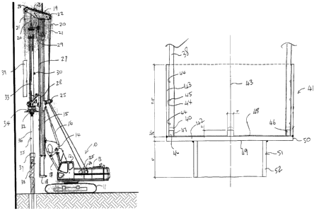
The apparatus generally comprises a tractor unit 10 of a conventional
nature mounted on tracks 11 and including a cab 12 and a drive system 13. The
tractor carries a support system 14 for carrying a mast 15. The support system
14 is
generally of a conventional nature and includes cylinders 16 and 17 which
allow the
height and inclination of the mast 15 to be adjusted. The mast 15 includes a
foot 18
which is arranged to be located on the ground in front of the tractor 10 so as
to
locate the mast for operating upon an area of the ground in front of the mast
and in
front of the tractor.
CA 02468358 2004-06-18
11
At the top of the mast is provided an arm 19 which provides a
support for a pair of cables 20 and 21 which extend to the arm over pulleys 22
and
at 23 so as to depend downwardly in front of the mast and one in front of the
other.
The cables are guided over pulleys 25 part way along the rear of the mast so
as to
direct the cables from the arm 19 to winches 25 and 26 provided in the drive
assembly 13 of the tractor. Thus each of the cables can be actuated
independently
to raise and lower the elements attached thereto on the front of the mast.
The mast further includes a guide track 27 which guides movements of
support trolleys 28 and 29 of the tools to be moved along the length of the
mast on
the cable 20.
The tool carried on the cable 20 comprises a drive and rotation tool
generally indicated at 30 which is of a commercially available construction
and
includes an upper arm 31 attached to the trolley 29 and a lower mounting 32
attached to the trolley 28. In-between the two mountings is provided a drive
structure 33 in the form of a tubular member supporting the drive components
and
providing a rigid structural support between the trolleys 29 and 28 so that
the
structure is maintained vertical or parallel to the mast when vertical so as
to provide
vertical drive at a head 34 of the tool below the mounting 32. The tool is
arranged to
provide at the head 34 bath rotation and vertical compression forces for
driving
various components into the ground.
The rotation is provided by a drive motor at the mounting 32 with the
drive motor being operable either to provide rotation in a continuous forward
CA 02468358 2004-06-18
12
direction, rotation in a continuous rearward direction or reciprocating
rotation back and forth through an angle less than 360 degrees.
Tools of this type are commonly available and examples can be
obtained from suppliers such as H & T Auger of Odessa Texas, W.F.J. Drilling
Tools
of Odessa Texas, Pengo Corporation and Texoma Drilling Tools of Sherman Texas.
The head 34 can therefore receive an auger flight far drilling a hole and
for lifting drilled soil from the ground in a well known manner as described
hereinafter or the head can receive a driving tool 35 for reciprocating
driving
movement of a tool as described herein after. The tool 35 comprises a drive
shaft
36 attached to a drive head 37 which drives movement of a tube 38, all forming
part
of the tool 35. The action of the tool is described in more detail herein
after.
The cable 21 carries a hammer 39 which is operated by simple lifting
and dropping as an impact hammer for operating in the method described
hereinafter.
Turning now to Figures 7 through 10, there is shown a shoe for
mounting at the bottom end of the tube 38 as part of the pile installation
tool 35.
Thus the tube 38 has a bottom end 40 to which is attached the shoe 41. The
shoe
41 includes a bottom wall 42 which lies in a radial plane of the longitudinal
axis 43 of
the tube so as to close the lower end of the tube. The shoe 41 includes a
sleeve 43
attached to the bottom wall 42 and directly surrounding the bottom end 40. The
sleeve 43 has a series of grooves 44 at axially spaced positions therealong
each
receiving an O-ring seal 45 carried in the groove and projecting inwardly from
an
CA 02468358 2004-06-18
13
inside surface of the sleeve 43. The O- rings seals thus act as a seal
relative to
the outside surface of the tube 38 so that the sleeve and bottom wall 42 of
the shoe
act as a closure for the lower end of the tube thus preventing the entry of
water into
the tube. The sleeve is however a sliding fit on the outer surface of the tube
so that
the sleeve and the bottom wall can move downwardly relative to the end of the
tube.
The sleeve carries at its bottom edge at the wall 4~'. a plurality of block
elements 46 which act as keys inserted into corresponding recesses 47 in the
bottom end of the tube 38. Thus the shoe can be inserted in place on eh bottom
end
of the tube and the plurality of blocks 46 at angularly spaced positions
around the
end of the sleeve inserted into corresponding openings or recesses at the end
of the
tube 38 similarly angularly spaced. Thus rotational movement of the tube is
transferred into rotational movement of the shoe.
The end plate 42 lies in a radial plane so as to define an upper surface
40A which is flat within the area bounded by the blocks 46. The plate 42 also
defines a bottom surface 49 which is also flat and lies in a radial plane so
as to
provide compression of material underneath the surface 49. The plate 42 and
its
surface 49 extends to the outer edge of the plate at the edge of the sleeve so
as to
form and outermost edge portion 50. On the underside of the plate 42 is
attached a
ground engaging member 51 formed by a plurality of blades 52 connected to form
a
generally H-shaped member. The blades lie at right angles to the bottom
surface 49
that is at right angles to a radial plane of the axis. The blades are arranged
so they
do not form a closed hollow area but instead allow material disturbed by
rotation of
CA 02468358 2004-06-18
14
the shoe to move outwardly from the axis 43 toward the outer edge 50.
In the embodiment shown the blades are arranged at right angles and
attached together as an integral structure in a Fi-shape. However alternative
arrangements of the blades can be provided where the blades extend outwardly
from a position closer to the axis to a position further away from the axis
thus
tending to cause the material to move outwardly and to break up material as
the
rotation occurs. An alternative arrangement could include blades which are
connected together at the central axis and extend radially outwardly
therefrom. The
blades preferably terminate at a position spaced from the outer edge 50 so
that the
main part of the bottom surface 49 is available as a compression tool. The
ground
engaging member 51 and the plate 42 and the sleeve 43 are all attached
together
integrally as an integral structure which can be inserted onto the tube but
removed
from the tube by the sliding action of the sleeve relative to the outer
surface of the
tube.
In Figure 11 is shown in more detail the cross section of the head 37
by which the top of the tube 38 is grasped to provide downward force on the
tube
and also to provide rotational force to the tube generated by the head 32. In
addition
the head 37 has a hollow interior which allows the cable 21 to pass through
the
hollow interior of the head 37.
The head 37 as shown in Figures 11, 12, 13 and 14 includes a
receptacle 37A which forms a square cross :'ection tube proceeding the
conventional lower engagement end of the drive coupling of the tool. The
receptacle
CA 02468358 2004-06-18
37A has sufficient length and sufficient strength to accommodate the high
torque necessary for communicating forces from the drive to the tube 38. The
drive
tool improves the Ivwer end of a shaft which engages into the receptacle to
provide
both downward pressure and rotation forces form the head of the tool.
5 The head further includes a top plate 3~7B which is arranged to receive
downward pressure from a collar of the guide tool, if required. The guide tool
thus
includes a collar and the drive shaft which can be moved upwardly and
downwardly
independently of one another so that when more energy is required to apply
significant downward force on the head, the collar of the tool is engaged onto
the
10 upper edge 37B of the head. The plate 37B is connected to the receptacle
37A by
priority of ribs 37C and by interconnecting fuller pieces 37D. This forms a
hollow
area 37E inside the wall beside by the rib and fellow pieces and underneath
the
upper flange 37D. The bottom of the hollow interior is closed by a priority of
transverse wall pieces 37E. One of the pieces indicate at 37F is omitted to
provide
15 an opening of the bottom of the hollow interior 37G.
At the bottom of the ribs 37C is attached the transverse plate 37H
which provides a force transfer plate attached to the receptacle 37A and to
the ribs
through which the longitudinal and rotational forces are communicated into the
plate
37H. On the underside of the plate 37H is attached two tube coupling elements
37J
and 37K. Each of these is formed by a cylindrical wall and the base plate 37L
and
37N respectively which are attached to the plate 37H. The cylindrical wall has
a
diameter matching that of the tube to be driven. Thus the two separate
coupling
CA 02468358 2004-06-18
16
elements 37J and 37K are designed for two separate tube diameters. It will be
appreciated that only one coupling element may be provided or more than two
can
be provided so as to accept different diameters of tube as required. The
cylindrical
wall of each coupling is castellated so as to match a corresponding
castellated
section at the top of the tube. Each coupling includes also a chamfered guide
37P,
37Q respectively where each guide is formed by four separate flange elements
which are chamfered so as to guide the tube to center the tube on the common
axis
with the respective coupling and hold it in place during the communication of
longitudinal and rotational forces.
A hole 37R is formed through the plate 37H, 37L and 37N which is
generally aligned with the opening 37S to allow the passable of the support
cable 21
for the hammer. Thus the support cable 21 as best shown in Figure 11 passes
through the hollow interior 37G along side the drive shaft (not shown)
engaging into
the receptacle 37A and then passes through the opening 37F to the hole 37R
where
it can enter into the interior of the respective tube attached with the
respective
coupling 37J or 37K.
The ground construction is shown in the figures and includes an
overburden of sedimentary clay 55 which extends from the ground surface 56 to
a
top surface 57 of a layer of glacial till 58. The depth of the clay varies in
various
locations. The glacial till is common in areas where receding glaciers have
eroded
the soil to provide the till with an upper surface and a thickness through the
till which
also can vary down to bedrock below the till. The intention is to provide a
pile which
CA 02468358 2004-06-18
17
extends through the sedimentary clay which is unsuitable to support the pile
and into an upper surface of the till. The till is well known to provide
sufficient
support for a pile but only if compression of the till occurs up to a certain
suitable
level to provide a required resistance to downward movement of the pile on
application of a load from the ground surface. The intention is therefore to
provide
the pile buried within the till with compression of the till underneath of the
pile while
avoiding the necessity for driving a preformed pile form the surface.
Turning now to the method of installation of the pile as shown in
Figures 1 through 6, a series of steps are shown utilising the elements
described
above.
In the first step of Figure 1 the head 34 on the tool 30 is used with the
mast vertical in position at a required pile location 60 to drill a hole 61.
The hole 61 is drilled through the clay 55 to the upper surface 57 of the
till. Drilling through the clay is relatively straightforward since the clay
is sedimentary
and thus contains little in the way of large boulders or obstacles which can
intertere
with the drilling process. Drilling through the clay is generally necessary
for a
distance of the order of 7.0 to 15.0 meters depending upon the location. The
drill
action is carried out using conventional methods in which the auger flight 63
is drilled
into the ground and extracted to remove the earth carried on the flight
allowing a
further drilling action to occur.
In this state the cable 21 remains unused and the drilling action is
effected using the tool 30 moving in a sliding action along the mast 15.
CA 02468358 2004-06-18
18
Turning now to Figure 2, when the drilling action is complete, the
auger is removed and the tube 38 installed into the drilled hole 61 using the
lifting
action of the cable 21 and its winch 26. On the bottom of the tube 38 is
attached the
shoe 41 which is inserted in place and held in place by the frictional fit
between the
sleeve and the outer surface of the tube. The tube is thus dropped to the
bottom of
the drilled hole and thus sits on the upper surface 57 of the till 58..
As shown in Figure 3, the cable 21 is released from the upper end of
the tube 38 exposing the upper end of the tube 38 of the top of the hole 61.
The
head 34 has the auger flight removed therefrom and replaced by the tool 35
including the connecting rod 36 engagement head 37 which engages onto the top
of
the tube 38. The drive head 34 is changed in operation from the continuous
rotation
mode for the drilling action using the auger flight to a reciprocating mode in
which
the head 37 is reciprocated back and forth generally of an angle less than 360
degrees. At the same time the head 34 is arranged to apply pressure downwardly
onto the connecting rod 36 and the head 37 thus applying pressure to the tube
38
and the shoe 41. The application of pressure together with the back and forth
reciprocation of the tube 38 and therefore of the shoe 41 causes the shoe 41
to work
its ways downwardly into the till by a compression action and reciprocation
action
which compresses the material underneath the shoe and also diverts the
material
outwardly to the sides of the shoe.
It is well known and well established that such a reciprocation action
known as a "displacement pile" only allows the shoe to be worked into the till
over a
CA 02468358 2004-06-18
19
relatively short distance with insufficient compression of the till material
to provide
sufficient support of the pile to accommodate suitable loadings at the ground
surface. Such displacement piles are therefore only rarely used and are
generally
unsatisfactory,
Turning now to Figure 4, the further stage in the process involves the
removal of the head 37 from the top of the tube 38 temporarily to expose the
open
top of the tube 38. This action is effected by temporarily lifting the tool 35
on the
head 34 to expose the open top of the tube. In this position the hammer 39
which is
lifted on the cable 21 is lowered into the open upper mouth of the tube so as
to enter
the hammer 39 into the interior of the tube so as to slide downwardly to the
bottom
of the tube. With the hammer in place in the tube and the cable passing
through the
open mouth, the tool 35 is returned to its initial position so that the head
37 is
reapplied to the top of the tube 38.
In this arrangement as shown in Figure 4, the impact hammer 39 can
be actuated by raising the hammer within the tube to the top of the tube,
allowing the
hammer to drop along the tube to impact on the upper surface 48 of the shoe.
This
impacting action on the shoe applies impact forces directly to the shoe at an
area
deep within the ground and within the till so as to drive the shoe downwardly
relative
to the tube. The tube is held in the tool 35 by the head 37 so the tube tends
to
remain in place as the shoe is driven downwardly thus providing relative
movement
between the shoe and the tube driving the show downwardly away from the bottom
end of the tube. This movement occurs only over a short distance which is
generally
CA 02468358 2004-06-18
of the order of or less than 25mm so that the amount of movement allows the
bottom end of the tube to remain within the sleeve and the tabs or blocks of
the shoe
to remain in engagement with the respective receptacles at the bottom end of
the
tube. With the tool 35 thus applying downward compressive forces on the tube,
the
5 tube is thus gradually compressed back to its position up against the upper
surface
of the shoe while the reciprocating action of the tube and the shoe is
repeated. This
impacting action thus acts to vigorously compress the material underneath the
shoe
downwardly by the bottom surface of the shoe and then the reciprocating
rotation
causes the ground engagement blades to break up or excise the material
10 underneath the bottom surface causing it to be expelled outwardly from the
axis of
the tube. It has been found that this repeated impacting at the shoe together
with
the compression of the tube and the reciprocating action of the tube causes
the shoe
to be driven downwardly within the till to a greater distance.
Typically initial operation using reciprocation and compression as
15 shown in Figure 3 causes the shoe to be driven into the till by a distance
of the order
of 0.5 meters. The further operation provided by the impacting action followed
by
the reciprocating and compression can act to drive the shoe further into the
till by a
distance of the order of 1.0 meters leading to a total depth of the order of
1.5 meters
within the till. This distance has been found to provide sufficient
compression of the
20 material underneath the bottom of the shoe to provicle a resistance against
the pile
sufficient to accommodate up to 1200KN loading on the top of the pile.
When the driving action of the method shown in Figure 4 is complete,
CA 02468358 2004-06-18
21
that is it has reached the stage where no further movement is obtained by the
application of the compressive and reciprocating forces and by the application
of the
impact from the hammer, the tool 35 is removed from the tube 38.
With the tube 38 remaining temporarily in place, a poured concrete pile
is formed within the tube using conventional techniques so that the poured
concrete
sits on the shoe 41 at the bottom of the hole and applies loading from the
ground to
the shoe. Poured concrete piles of this type are well known and utilize the
necessary reinforcing bars and concrete material so that the loading can be
effectively transferred from the ground through the poured concrete reinforced
pile to
the shoe so that the loading is applied to the shoe and through the shoe to
the
compressed material underneath the shoe within the till.
After pouring the concrete, the tube 38 us lifted by tree winch 26 and the
cable 21 so as to lift the tube out of the hole 61 leaving the shoe and
concrete in
position in the hole. The shoe remains in position due to its vigorous
engagement
into the material within the till at the bottom of the hole which overcomes
the sliding
friction between the tube and the inside of the sleeve. Thus lifting the tube
causes
the lower end of the tube to slide out of the sleeve and the tube to be
extracted from
the hole 61 for reuse.
As set forth above a pile of this sort can provide a loading at the
surface of at least 450KN and preferable of the order of 800KN to 1200KN.
These
loadings approximate to the level of loading which can be obtained by a
conventional driven pile. However the structure is simpler, less expensive and
less
CA 02468358 2004-06-18
22
damaging to the environment than is the conventional driven preformed concrete
pile.
In a first alternative, the impacting action can be applied directly when
the shoe and tube are inserted into the ground so that all of the driving
action of the
shoe is effected using both the impacting action together with the driving and
reciprocating action on the top of the tube.
In the further alternative arrangement, the tube and shoe can be
formed as an integral structure so that the impacting action on the shoe
drives both
the shoe and the tube simultaneously downwardly. This arrangement requires
that
there is a slip coupling either at the head 37 or at the head 34 so as to
allow the tube
to move downwardly relative to the head under the impact action. It will be
appreciated that the instantaneous movement caused by the impacting action
cannot be accommodated in the head 34 or the head 37 without the application
of
such a slip connection since it would cause damage to the hydraulic system
which
provides the gradual compression forces and provides the rotation action. In
this
arrangement it is generally necessary to leave the tube and shoe in place so
this is a
less preferred method particularly from the cost point of view though it is
practically
possible to provide a pile structure in a manner which is more effective and
less
expensive than the conventional drive preformed pile.
Since various modifications can be made in my invention as herein
above described, and many apparently widely different embodiments of same made
within the spirit and scope of the Claims without department from such spirit
and
CA 02468358 2004-06-18
23
scope, it is intended that all matter contained in the accompanying
specification shall be interpreted as illustrative only and not in a limiting
sense.