Note: Descriptions are shown in the official language in which they were submitted.
CA 02468444 2004-06-10
WO 03/053229 PCT/GB02/05573
Eye Speculum
Description
The present invention relates to an eye speculum used by ophthalmologists
during
micxosurgical procedures to retract and retain the eyelids away from the
surface of
the eyeball.
In the field of ocular surgery, one of the most common operations is the
removal of
cataracts, and currently around 179,000 are performed each year in the UK.
During
70 these and other eye operations, the patient's eyelids are held apart using
an eye
speculum to expose the surface of the eye in the region of the pupil and iris
to
enable the required surgical procedure to be performed.
The majority of conventional eye speculums have a pair of metal blades each of
which is mounted on the end of a wire arm. Alternatively, the speculum is
formed
entirely of wire, the blades being replaced with integrally formed wire loops
at the
end of each arm. A blade ox wire loop on each arm is hooked around or
otherwise
engages the upper and lower eyelid respectively to retract the eyelids. The
opposite
ends of each arm are connected together so that spring tension between the
arms
holds the blades or loops apart. The surgeon squeezes the arms together
against the
biasing force during insertion of the blades or loops and then releases them
so that
the spring tension forces the eyelids open. Alternatively, the angular
relationship of
the arms can be controlled via a complicated mechanical linkage.
A disadvantage with conventional eye speculums, such as those described above,
is
that they provide little or no stability to the eyeball, they exert excessive
pressure to
the eyelids in the region of contact of the speculum, they axe difficult to
insert and
axe uncomfortable for the patient. Furthermore, due to the materials from
which
conventional speculums are made, they can cause abrasion and injury to the eye
socket and surrounding tissue during insertion or after prolonged use. They
also
tend to be expensive to manufacture so there is a reluctance to dispose of
them
after each use, the majority of speculums being sterilised and used again for
this
reason.
CA 02468444 2004-06-10
WO 03/053229 PCT/GB02/05573
It is an object of the invention to provide an eye speculum that overcomes or
substantially alleviates the disadvantages with conventional speculums
described
above.
According to the present invention, there is provided an eye speculum
comprising a
moulded flexible shell configured for insertion into an eye socket so as to
contact
and envelop part of an eyeball, the shell having an opening therein to provide
access
to the eyeball for ocular surgery or examination.
Preferably, the shell comprises a waist region forming the periphery of the
opening
and a flared skirt depending from the waist region.
The flared skirt is preferably part spherical in shape. The skirt and eyeball
together
form a "ball and socket" type joint that provides stability to the eyeball.
Conveniently, at least one aperture is formed in the flared skirt. This allows
fluids to
pass through the skirt and around the eyeball to prevent it from drying out.
20 In one embodiment, the waist portion and the flared skirt are C-shaped.
This makes
the speculum even more flexible for ease of insertion.
The waist region and flared skirt may be integrally formed.
25 Preferably, the waist region comprises an annular strengthening ring.
In one embodiment, the annular strengthening ring is separable from the flared
skirt
and may advantageously carry graphical markings indicating angular degree
increments around the periphery of the opening.
In an alternative embodiment, a strengthening ring may be concealed within the
waist region.
CA 02468444 2004-06-10
WO 03/053229 PCT/GB02/05573
Preferably, at least one conduit extends from the waist region to the inner
surface of
the flared skirt for the passage of fluid to the eyeball through the speculum.
Advantageously, the inner surface of the skirt includes at least one capillary
channel
extending from the conduit to draw fluid away from the conduit.
In any of the preferred embodiments, eyelid retaining members upstand from the
waist member and may comprise a pair of arcuate flanges or wings, or two
groups
of spaced fingers.
The conduit may extend through the eyelid retaining members.
In another embodiment, the waist region includes at least one arcuate sleeve
that
extends partially around the periphery of the opening, an end of the or each
sleeve
being open to receive and mount a removable handle to the speculum.
Preferably, the or each sleeve is partially open along its length to form a
channel.
The speculum may additionally comprise a handle member having a portion
20 configured for insertion into the or each sleeve to removably mount the
handle
thereto and a body portion for holding the speculum.
The body portion of the handle preferably extends laterally from the speculum
in
the plane of the waist region.
In a preferred embodiment, the waist region includes a pair of sleeves and the
handle is two forked arms, the end of each arm being inserted into a
respective
sleeve to mount the handle to the speculum, said arms being flexible to allow
the
speculum to be deformed during insertion by squeezing said arms together.
The speculum is preferably moulded from plastic or silicon rubber.
CA 02468444 2004-06-10
WO 03/053229 PCT/GB02/05573
As the speculum of the present invention is cheap to manufacture in comparison
with conventional speculums, it may be thrown away after a single use thus
avoiding
the requirement to sterilise them. This is a particularly significant
advantage as
known sterilisation processes are not 100% effective and is even more
important
with the occurrence of vCJD (the human form of mad cow disease) and the
possibility of cross-tool contamination widely acknowledged as a problem with
the
sterilisation of non-disposable surgical tools.
Embodiments of the present invention will now be described, by way of example
70 only, with reference to the accompanying drawings, in which:-
FIGURE 1 shows an eye speculum according to a first embodiment of the present
invention;
FIGURE 2 shows a modified version of the eye speculum of the first embodiment
incorporating irrigation or anaesthetic conduits;
FIGURES 3 and 4 show two further modifications of the first embodiment;
FIGURE 5a show two cross-sectional views through the eye speculum of Figure 1;
FIGURE 5b shows two cross-sectional views through the eye speculum of Figure
2;
FIGURE 5c shows two cross-sectional views through an eye speculum according to
a second embodiment;
FIGURE 5d shows two cross-sectional views through an eye speculum according to
a third embodiment;
FIGURE 6 shows an eye speculum according to a fourth embodiment;
FIGURE 7 shows the eye speculum of Figure 1 mounted on an eyeball;
FIGURE 8 shows an eye speculum according to a fifth embodiment;
FIGURE 9 shows the wire handle shown in Figure 8;
FIGURE 10 shows a modified version of the fifth embodiment illustrated in
Figure
8;
FIGURE 11 shows a C-shaped speculum with an integral eye drape, and
FIGURE 12 shows a non C-shaped or closed type speculum with an integral eye
drape.
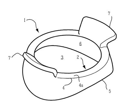
Referring now to the drawings, there is shown in Figure 1, an eye speculum 1
according to a first embodiment of the present invention in the form of a
moulded
CA 02468444 2004-06-10
WO 03/053229 PCT/GB02/05573
flexible shell comprising a waist portion 2 forming the periphery of an
opening 3
and incorporating a stiffening or rigidifying ring 4 only the upper surface 4a
of
which is visible, and a flared skirt portion 5 which is part spherical in
shape and has
a concave inner wall 6. Optional flanges 7 to assist in retaining the eyelids
and/or
5 eyelashes away from the eye upstand from the waist portion 2. The skirt 5,
waist
portion 2 and the flanges 7 are integrally formed from a resilient moulded
flexible
material such as silicon rubber.
A modified version of the first embodiment is illustrated in Figure 2. The eye
70 speculum 1 of this version is additionally provided with an irrigation tube
or
conduit 9 extending through each of the flanges 7 to an outlet 8 in the inner
wall 6
of the skirt 5. A capillary channel 10 extends away from the outlet 8 to draw
fluid
away from the outlet 8 and over the surface of the eyeball beneath the skirt
5.
Alternatively, the conduit 9 can be used for the insertion of a curved needle
often
75 used by surgeons during ocular surgery to apply anaesthetic to a region
toward the
rear of the eyeball.
Two further modified versions of the eye speculum 1 shown in Figure 1 are
illustrated in Figures 3 and 4. In Figure 3, the flanges 7 have been replaced
by a pair
20 of open loops or frames 11, and in Figure 4, the flanges 7 have been
replaced with
two sets of fingers 12.
Figure 5a shows two cross-sections through the eye speculum 1 shown in Figure
1.
The position of the stiffening ring 4 embedded within the mould can be seen in
the
25 waist region 2. In Figure 5b, which shows two cross-sectional views of the
speculum 1 shown in Figure 2, the path of the irrigation conduits 9 are
clearly
visible and it will be appreciated that the conduit 9 passes through the
stiffening
ring 4, an aperture being provided in the stiffening ring 4 for this purpose.
In the
embodiment of Figure 5c, the stiffening ring 4 and the flanges 7 are
integrally
3o formed, the ring 4 and flanges 7 being co-moulded with the skirt 5. The
skirt 5 may
be formed from a different, softer or more flexible material than the ring 4
and
flange 7 so that it flexes and conforms more easily to the shape of the
eyeball.
Figure 5d' shows a speculum Which is similar to the speculum illustrated in
Figure
CA 02468444 2004-06-10
WO 03/053229 PCT/GB02/05573
6
5c, except that the integrally formed ring 3 and flanges 6 axe a snap fit with
the skirt
formed as an entirely separate component. Lugs or bosses 13 are formed on one
part, which engage with corresponding recesses in the mating part.
5 Figure 6 illustrates another embodiment in which an opening 14 extends
through
each flange so that irrigation tubes 15 can be connected thereto and
irrigating fluid,
indicated by "A" on the figure, fed through the tubes and openings 14 onto the
front face of the eyeball to prevent it from drying out during surgery.
70 Figure 7 shows the eye speculum according to the invention mounted on an
eyeball
16. The surgeon may work on the iris or pupil through the opening 2a whilst
the
eyelids and eyelashes are held in a retracted position by the speculum 1.
Another embodiment of speculum according to the invention is shown in Figure
8.
75 In this embodiment, the speculum 18 is C-shaped to enable it to be flexed
more
easily during insertion. As it does not completely surround the eyeball 16, it
also
may cause less trauma or discomfort to the patient. It will be appreciated
that any
of the embodiments described above may also be C-shaped.
20 The speculum 18 is provided with a pair of arcuate sleeves 19 around the
periphery
of the opening 3 which are integrally formed on the waist region 2. Each
sleeve has
a central closed section 20 between two open channels 21. One end 22 of each
channel 21 is open to enable insertion of the ends of a bent wire handle 23 to
mount the handle 23 to the speculum 18. The speculum 18 may be used with or
25 without the handle 23 and can be easily removed. This is important as a
handle 23
can often obstruct the surgeon when performing intricate eye surgery.
The handle 23 can be seen more clearly from Figure 9. It comprises a length of
wire
or rod bent to form a pair of identical forked arms 24. The free ends of each
arm 24
30 are curved to correspond to the curvature of the arcuate sleeves 19 in the
speculum
18 and have a depression 25 thereon in which the central closed section 20 of
a
sleeve 19 locates to mount the handle 23 to the speculum 18. It will be
appreciated
that the arms 24 may be squeezed together to partially squash the speculum 18
to
CA 02468444 2004-06-10
WO 03/053229 PCT/GB02/05573
enable insertion into the eye socket, the arms 24 returning to their normal
configuration, as shown in Figures 8 and 9, when pressure applied to them is
released. The ends of each arm 24 received in the sleeves 19 act as a
stiffening
member for the waist region 2 so the stiffening member 4 is not required in
this
embodiment but may still be included so that the speculum can be used without
the
handle 23.
Figure 10 shows another type of C-shaped eye speculum according to an
embodiment of the invention which is similar to the non C-shaped ox closed
version
70 illustrated in Figure 1 although a portion of the flanges 7 fox retaining
the eyelids
and holding the eyelashes out of the way are partially cut away to form two
flange
portions 7a, 7b. The embodiment of Figure 10 may be provided with means to
enable the wire handle of Figure 8 to be attached and/or have irrigation tubes
or
conduits such as the embodiment of Figure 2.
Figure 11 illustrates another C-shaped speculum which incorporates an integral
eye
drape 30 that extends angulaxly away from the waist region 2 or stiffening
ring 4.
This omits the need for the surgeon to mask the eye with a secondary drape
during
a surgical procedure.
Figures 12 and 13 show a top and bottom perspective view respectively, of how
an
integral eye drape 31 may be incorporated into one of the non-C shaped or
closed
ring eye-speculums such as those described in more detail above.
The present invention provides an eye speculum that is cheap to manufacture
and
easier to use than those currently available. It is also more comfortable for
the
patient and provides stability to the eyeball.
Many modifications and variations to the invention falling within the terms of
the
following claims will be apparent to those skilled in the art and the
foregoing
description should be regarded as a description of the preferred embodiments
only.