Note: Descriptions are shown in the official language in which they were submitted.
CA 02468954 2004-06-O1
WO 03/055553 PCT/US02/40376
SURFACE ENERGY ASSISTED
FLUID TRANSPORT SYSTEM AND METHOD
CROSS-REFERENCE TO RELATED APPLICATIONS
This patent application claims the benefit of priority, under 35 U.S.C.
Section 119(e), to Roger N. Johnson U.S. Provisional Patent Application Serial
Number 60/343,495, entitled "SURFACE ENERGY ASSISTED FLUID
TRANSPORT SYSTEM," filed on December 21, 2001; and U.S. Patent
Application Serial Number 10/xxx,xxx filed on December 16, 2002.
FIELD OF THE INVENTION
This document relates generally to fluid transportation, and
particularly, but not by way of limitation, to surface energy assisted
systems and methods for transporting fluids.
BACKGROUND
When a patient is unable to adequately breathe independently, an external
mechanical ventilator may be used to provide temporary or permanent breathing
support. The ventilator pumps air into and out of the subj ect's lungs such
as, for
example, though an endotracheal (ET) or other tracheal tube. In one example, a
distal portion of the tracheal tube is introduced into the subject's trachea
(windpipe) through an incision made in the subject's throat. A proximal
portion
of the tracheal tube is connected to the ventilator. An inflatable cuff near
the
distal end of the tracheal tube is inflated to completely occupy the
intratracheal
region surrounding the tracheal tube. This creates a seal that prevents
airflow
through the trachea other than through the tracheal tube, so that the
ventilator
can provide the subject with breathing support through the tracheal tube. In
another example, the tracheal tube is inserted via the subj ect's mouth,
rather than
into am incision in the subject's throat.
However, normal lungs continuously secrete mucus that is sticl~y enough
to trap foreign particles. In the absence of the ventilator and tracheal tube,
such
secreted mucus would be carried up the windpipe to the throat by the action of
CA 02468954 2004-06-O1
WO 03/055553 PCT/US02/40376
cilia, such that the patient may then swallow the mucus. When damage or
disease disables this mechanism, or reduces its ability to move the required
volume of mucus, there exists a risk of the lungs drowning in fluid. In
addition,
certain medical procedures may disrupt such normal mucus transport. For
example, the inflatable cuff at the distal end of a tracheal tube inserted
into a
person on a ventilator will block the normal flow of the lung-cleansing mucus.
One technique for removing accumulated fluid from the lungs includes
interrupting the patient's ventilation by disconnecting the proximal end of
the
tracheal tube from the ventilator. A suction tube is then inserted through the
tracheal tube beyond the cuff at its distal end. By applying an airflow-
creating
vacuum to the proximal end of the suction tube, fluid is removed from the
lungs.
However, such an airflow-creating vacuum has a limited capability to lift
fluid
through a small diameter tube against the force of gravity, to remove the
fluid
from the lungs. Moreover, this procedure must be repeated often enough (e.g.,
every 0.25 to 8 hours). Otherwise, the mucus may accumulate or dry, which, in
tum, may make its removal more difficult. Each occurrence of such airflow
suctioning interrupts the breathing assistance provided by the ventilator.
Moreover, such airflow suctioning rislcs damage to the windpipe walls. It also
creates a risk of infection to both the patient and the caregiver, who may
come in
contact with the extracted fluids or the air used to suction the fluid. The
risk of
infection is exacerbated because the suction tube is typically re-used despite
its
contamination and direct connection to a waste container that stores the
suctioned fluid. Moreover, frequent intervention by a caregiver is aggravating
to
the patient, and may cause considerable resulting anxiety. Such frequent
intervention by a caregiver is also costly. In addition, the caregiver must be
well-trained to reduce the risks of damage or infection presented by such
repeated suctioning. Among other things, the present inventors have recognized
that continuous airflow-assisted suctioning, however, would likely interfere
with
the patient's breathing because of the airflow required to vacuum the fluid
from
the lungs. For these and other reasons, the present inventors have recognized
an
2
CA 02468954 2004-06-O1
WO 03/055553 PCT/US02/40376
unmet need for improved fluid transportation techniques, such as fox removing
mucus from a patient's lungs that are being mechanically ventilated, or for
otherwise removing bodily fluids from a patient.
BRIEF DESCRIPTION OF THE DRAWINGS
hz the drawings, which are not necessarily drawn to scale, like numerals
describe substantially similar components throughout the several views. Like
numerals having different letter suffixes represent different instances of
substantially similar components. The drawings illustrate generally, by way of
example, but not by way of limitation, various embodiments discussed in the
present document.
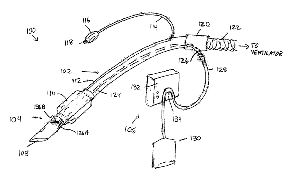
Figure 1 is a perspective view of one example of a system including a
tracheal tube assembly, a fluid pickup assembly, and a pump assembly.
Figure 2 is a cross-sectional view of one example of a distal portion of
the tracheal tube assembly inserted within a portion of a patient's trachea.
Figure 3 is a cross-sectional view taken along the cutline 3 - 3 of Figure
2.
Figure 4 is a cross-sectional view taken along the cutline 4 - 4 of Figure
2.
Figure 5 is an exploded perspective view of one example of a portion of
the fluid pickup assembly including hollow tubular bent "V" collection prongs
attachable in fluid communication with corresponding fluid removal lumens.
Figure 6 is a perspective view illustrating in more detail the region 6 in
Figure 5.
Figure 7 is a cross-sectional view taken along the cutline 7-7 of Figure 6.
Figure 8 is an exploded perspective view of one example of a portion of
the pickup assembly, illustrating collection prongs located within a trachea.
Figures 9A, 9B, 9C, 9D, 9E, and 9F are conceptualized schematic
diagrams of one example of operation of portions of a fluid pickup assembly
including a collection prong and fluid pickup ports.
3
CA 02468954 2004-06-O1
WO 03/055553 PCT/US02/40376
Figure 10 is an exploded perspective view of one example of portions of
a pump assembly, which is couplable to portions of the tracheal tube assembly.
Figure 11 is a cross sectional view of a portion of the pair of fluid
removal tubes taken along the cutline 11-11 of Figure 10.
Figure 12 is a flow chart of one example of operation of portions of the
system for removing mucus during mechanical ventilation of a patient using the
tracheal tube assembly.
Figure 13 is a cross-sectional side view of one example of a portion of a
fluid pickup assembly that includes a pair of fluid collection prongs located
on
an opposite side of the fluid pickup assembly from another pair of fluid
collection prongs.
Figure 14 is a cross-sectional view taken along the cutline 14 -14 of
Figure 13.
Figure 15 is a cross-sectional side view of one example of a portion of a
fluid pickup assembly using a distal sidewall portion of a cuff for wicking
mucus
toward entry portals.
Figure 16 is a cross-sectional view taken along the cutline 16 -16 of
Figure 15.
Figure 17 is a cross-sectional view talcen along the cutline 17 -17 of
Figure 15.
Figure 18 is a cross-sectional side view of one example of fluid pickup
assembly portions of the system.
Figure 19 is a cross-sectional side view of one example of fluid picl~up
assembly portions of the system.
Figure 20 is an exploded side perspective view illustrating one example
of a two-piece tracheal tube assembly.
4
CA 02468954 2004-06-O1
WO 03/055553 PCT/US02/40376
Figure 21 is a perspective view, similar to Figure 1, illustrating one
example of a system including at least one wicking fluid pickup port located
below a cuff and at least one wicking fluid pickup port located above the
cuff.
Figure 22 is a side perspective view illustrating one example of a double-
lumen tracheal tube including at least one wicking fluid pickup port.
Figure 23 is a side perspective view illustrating one example of a
bronchial blocker assembly including at least one wicking fluid pickup port.
Figure 24 is a schematic diagram illustrating generally one example of a
generalized system using surface energy assistance in transporting and/or
separating a fluid.
Figure 25 is a schematic diagram illustrating generally one example of a
drill bit including a wicking channel, such as for transporting a lubricant.
Figure 26 is a schematic diagram illustrating an example of a liquid
wicking channel in the interior portion of a conduit, and also illustrates one
example of surface-energy assisted fluid transport across a boundary between
regions having different pressures.
DETAILED DESCRIPTION
In the following detailed description, reference is made to the
accompanying drawings that form a part hereof, and in which is shown by way
of illustration specific embodiments in which the invention may be practiced.
These embodiments are described in sufficient detail to enable those skilled
in
the art to practice the invention, and it is to be understood that the
embodiments
may be combined, or that other embodiments may be utilized and that
structural,
logical and electrical changes may be made without departing from the scope of
the present invention. The following detailed description is, therefore, not
to be
taken in a limiting sense, and the scope of the present invention is defined
by the
appended claims and their equivalents.
CA 02468954 2004-06-O1
WO 03/055553 PCT/US02/40376
In this document, the terms "a" or "an" are used, as is cormnon in patent
documents, to include one or more than one. Furthermore, all publications,
patents, and patent documents referred to in this document are incorporated by
reference herein in their entirety, as though individually incorporated by
reference. In the event of inconsistent usages between this documents and
those
documents so incorporated by reference, the usage in the incorporated
references) should be considered supplementary to that of this document; for
irreconciliable inconsistencies, the usage in this document controls.
Figure 1 is a perspective view illustrating generally, by way of example,
but not by way of limitation, one embodiment of a system 100 that includes one
example of a tracheal tube assembly 102, a fluid pickup assembly 104 located
at
or near a distal end of tracheal tube assembly 102, and a pump assembly 106
coupled to a location that is at or near a proximal end of tracheal tube
assembly
102. In the example of Figure 1, tracheal tube assembly 102 includes an air
passage 108, extending longitudinally between the distal arid proximal ends of
tracheal tube assembly 102. A bladder-lilce inflatable cuff 110 (or other
seal) is
located about the outer circumference of tracheal tube assembly 102 near its
distal end. Inflatable cuff 110 is located above (more proximal than) fluid
piclcup assembly 104. A cuff lumen 112 extends through tracheal tube assembly
102 from cuff 110 to the proximal end portion of tracheal tube assembly 102.
For example, cuff lumen 112 may run integrally within a wall of tracheal tube
assembly 102, or as a separate tube extending through air passage 108.
In this example, at the proximal end portion of tracheal tube assembly
102, cuff lumen 112 is coupled in fluid communication with external cuff tube
114, which extends outwardly therefrom toward cuff pressure bladder 116 and
inflation port 118, or similar pump device for inflating cuff 110. Cuff 110 is
capable of being inflated when tracheal tube assembly 102 is disposed within a
lumen (e.g., within a patient's trachea). Inflating cuff 110 provides a seal
that
ensures that airflow occurs within air passage 108, rather than through the
trachea outside tracheal tube assembly 102. In one example, cuff 110 is
inflated
6
CA 02468954 2004-06-O1
WO 03/055553 PCT/US02/40376
by introducing air into inflation port 118, and by then compressing cuff
pressure
bladder 116 to force the air through external cuff tube 114 and cuff lumen 112
into cuff 110. The proximal end of tracheal tube assembly 102 terminates at an
end comlector 120. In this example, end connector 120 is sized and shaped to
allow coupling to a ventilator tube 122, which, in turn, is coupled to a
mechaucal lung ventilator. End connector 120 provides fluid communication
between ventilator tube 122 and air passage 108 of tracheal tube assembly 102.
In the example of Figure 1, fluid pickup assembly 104 is located at the
distal end of tracheal tube assembly 102. Therefore, in this example, when the
distal end of tracheal tube assembly 102 is introduced into a patient's
trachea,
fluid pickup assembly 104 is located within the patient below (more distal
than)
inflatable cuff 110. A fluid removal lumen 124 extends and provides fluid
communication between fluid pickup assembly 104 (located at or near the distal
end of tracheal tube assembly 102) and a coupling stem 126 (located at or near
the proximal end of tracheal tube assembly 102) or a like coupling device. A
fluid removal tube 128 is coupled in fluid communication with coupling stem
126, for further carrying the fluid being removed to a bag or other holding
receptacle 130. In this example, pump assembly 106 includes a constant volume
(CV) or other low volume pump 132, having a pump head 134 coupled to a
portion of fluid removal tube 128 for providing a negative pressure within
fluid
removal tube 128. Tlus assists in drawing a liquid column through fluid
removal
tube 128 to holding receptacle 130.
In this example, fluid pickup assembly 104 includes at least one wicking
fluid pickup port 136A-B. That is, the at least one fluid pickup port 136A-B
is
sized, shaped, made of a particularly selected material, and/or otherwise
configured to use interfacial surface energy (also referred to as surface
tension)
to introduce a bodily or other fluid (such as mucus or the like) into the at
least
one wicking fluid picleup port 136A-B. Interfacial surface energies cause a
resulting "skin" to form (or, conversely, a repulsion to occur) at an
air/liquid
interface boundary. Similarly, an attraction or repulsion between a liquid
fluid
7
CA 02468954 2004-06-O1
WO 03/055553 PCT/US02/40376
and its interface boundary with a solid may result because of its interfacial
surface energy. This interfacial edge effect can provide a capillary action
whereby a liquid is pulled into a small pipe, i.e., a capillary. The relative
value
of the surface energy of the solid wall and that of the liquid determines
whether
the liquid is more attracted to the wall (in which case a "wicking" occurs
which
pulls the fluid to the wall) or to itself (in which case it avoids "wetting"
the
wall). In the present case, the relative value of the surface energy will be
affected by, among other things, the size of the at least one fluid pickup
port
136A-B, the shape of the at least one fluid pickup port 136A-B, and the
material
characteristics of the portion of fluid pickup assembly 104 in which the at
least
one fluid pickup port 136A-B is formed, and the characteristics of the
air/fluid
interface.
In the example of Figure 1, fluid pickup assembly 104 is designed to use
the interfacial surface energy to draw the mucus or the like into the at least
one
fluid pickup port 136A-B of pickup assembly 104. Such fluid introduction by
wiclcing advantageously avoids potential damage to the windpipe ,sidewalls
that
might occur upon inserting a conventional airflow-based suctioning device
through air passage 108 after disconnecting tracheal tube assembly 102 from
the
ventilator. In the example of Figure 1, once the mucus or the like pulls
itself into
20' the at least one fluid pickup port 136A-B of fluid pickup assembly 104
using the
surface energy effect, it is then subjected to a negative pressure, such as
that
generated by remote external constant volume pump 132, to draw such fluid
toward holding receptacle 130.
In this example, fluid removal lumen 124, coupling 126, and fluid
removal tube I28 are each sized, shaped, made of a particularly selected
material, or otherwise configured such that the surface energy of the mucus
(or
similar bodily fluid) causes a "skin" to bridge the entire interior cross
section of
the conduit formed by these components. As a result, a column of mucus is
pulled by pump 132 through the conduit provided by these components
(recognizing that some suspended gas bubbles or solids may be present in the
8
CA 02468954 2004-06-O1
WO 03/055553 PCT/US02/40376
mucus column being pulled by pump 132). By contrast, conventional airflow-
based vacuum devices generally pull liquid fluid by using a large ratio of
entrapping air (or other gaseous substance) to the liquid fluid being
entrapped by
the air. This is because such airflow-based vacuum devices typically depend on
the air movement at the intake port to draw the fluid into the port, rather
than
using surface energy to draw fluid (i.e., "wick" the fluid) into the intake
port.
Although not required, in one example, the pressure provided by pump
132 is adjusted to remove fluid at a desired steady-state rate that is
selected such
that the extracted material passing through the conduit provided by fluid
removal
lumen 124, coupling 126, and fluid removal tube 128 is almost all liquid
(including, among other things, viscous liquids and liquid suspensions bearing
suspended solids and/or entrapped gas bubbles), rather than a liquid in
combination with a more than insubstantial amount of air or other gaseous
substance. This results from the wicking of the mucus or like fluid into the
at
least one fluid pickup port 136A-B using surface energy. Similarly, the degree
of wicking provided by the at least one fluid pickup port 136A-B can be
adjusted
to match or approximate the subject's mucus generation rate.
In one example, at least a portion of the conduit provided by fluid
removal lumen 124, coupling 126, and fluid removal tube 128 (at least up to
pump head 134) is designed in material and size such that liquid fluid being
transported can span a the inside diameter of said conduit. The design is such
that any air bubbles introduced at the at least one fluid pickup port 136A-B
preserve an intact air/liquid "skin" or "bridge" that spans the inside
diameter of
said conduit. As a result, such air bubbles can be conceptualized as being
carned along by the liquid column being transported as if they were a part of
that
liquid column. Therefore, entrapment by high airflow is not required or used
to
obtain the desired mucus removal. The components forming the conduit are
sufficiently rigid to prevent their collapse under the pressures used to move
the
fluid up against gravity and to overcome the viscosity and holding power of
any
fluid bridging the fluid pickup ports 136A-B.
9
CA 02468954 2004-06-O1
WO 03/055553 PCT/US02/40376
Because the fluid removal conduit is occluded by mucus or by the low
volume pump 132, such fluid removal does not interfere with the ventilation of
the patient being provided through air passage 108, as might be the case with
a
conventional airflow-assisted fluid removal. As one consequence, the present
systems and methods of mucus removal may (but need not) be provided
concurrent to the ventilation of the patient, such as continuously. This
avoids
interrupting ventilation of the patient, such as is required to provide
airflow-
assisted suctioning for fluid removal. Among other things, such continuous
mucus removal, therefore, avoids compromising patient breathing, reduces risl~
of damage and infection to the patient, reduces rislc of contamination of the
caregiver by waste products, improves the patient quality of life, and/or
reduces
cost for caregiver and health care provider.
In one example, the inner diameter of at least a portion fluid removal
lumen 124 is sized so as to be small enough to permit it to be bridged by the
fluid/air ",slcin" as a result of the interfacial surface tension. The
corresponding
size of the inner diameter of fluid removal lumen 124 can be conceptually
approximated as illustrated below using Equation 1. Equation 1 illustrates
that,
to obtain the desired bridging, the inner diameter of fluid removal lumen 124
must be small enough such that a column of the liquid of interest (e.g.,
mucus)
can be lifted by surface energy to a height just greater than the height, h,
of the
meniscus, as illustrated generally by Equation 1.
Equation 1
2~y~cosBe
h=
Y.Pe .g
In Equation 1, y is the surface tension value of the fluid, 6~ is the angle at
which the fluid contacts the inner circumference of the fluid removal lumen
124,
f- is the inner radius of the fluid removal lumen 124, Pe is the fluid density
in air,
and g is the acceleration due to gravity. Thus, in one example, the size of
the
inner diameter of fluid removal lumen 124 is increased until h equals the
height
CA 02468954 2004-06-O1
WO 03/055553 PCT/US02/40376
of the meniscus, as illustrated in Equation 1. Similarly, the size of the
inner
diameter of the wiclcing fluid pickup ports) 136A-B is determined as described
with respect to Equation 1.
Figure 2 is a cross-sectional view illustrating generally, by way of
example, but not by way of limitation, one embodiment of a distal portion of
tracheal tube assembly 102 inserted within a portion of a patient's trachea
200.
Figures 3 and 4 are cross-sectional views taken along the respective cutlines
3-3
and 4-4 of Figure 2. In the example illustrated in Figures 2-4, trachea 200
includes an inner tracheal wall 202 upon which a mucus coating 204 has
developed. Cuff 110 is illustrated, in this example, as having been inflated
to
seal trachea 200. In Figure 2, pickup assembly 104 includes pickup prongs
206A-B extending outwardly from pickup assembly 104, toward mucus coating
204, such as in a bent "V" configuration. Prongs 206A-B assist in collecting
the
moving sheet of mucus 204, and directing it toward the apex of the bent "V,"
near which fluid pickup ports 136A-B are located. In this example, each of the
fluid ports 136A-B is comlected to a separate one of fluid removal lumens 124A-
B, which, in this example, extend longitudinally within wall 208 of tracheal
tube
assembly 102 toward its proximal end. However, in another example, one or
more fluid removal lumens 124A-B extends as a tube running longitudinally
through air passage 108. In yet another example, one or more fluid removal
lumens 124A-B extends as a tube running along an exterior portion of tracheal
tube assembly 102, such as by passing beneath cuff 110, or even through cuff
110 (e.g., using appropriately sized folds in the wall of cuff 110 to provide
passage through cuff 110). A different number of fluid removal lumens 124 may
be provided, for example, corresponding to a different number of fluid pickup
ports 136. In one such example, system 100 includes a single fluid pickup port
136 and a corresponding single fluid removal lumen 124.
In one example, portions of system 100 are supplied as a kit including
different fluid pickup assemblies 104 (e.g., having differently sized prongs
206A-B). This allows the user to select an appropriately sized piclcup
assembly
11
CA 02468954 2004-06-O1
WO 03/055553 PCT/US02/40376
104 to more closely match one of several different possible sizes of trachea
200,
which may vary from patient to patient. Also, although Figures 1-3 illustrate
a
pair of fluid piclcup ports 136A-B, in another example, a larger number of
fluid
pickup ports 136 are used. This increases the number of surface energy
assisted
mucus collection sites. Such fluid pickup ports may be located in many
different
possible configurations.
Figure 5 is an exploded perspective view illustrating generally, by way of
example, but not by way of limitation, one embodiment of a portion of fluid
piclcup assembly 104 including hollow tubular bent "V" collection prongs 206A-
B attachable in fluid communication with corresponding fluid removal lumens
124A-B. In one example, prongs 206A-B are attachable to corresponding fluid
removal lumens 124A-B using snap-fit or other coupling ends 500A-B. In this
example, fluid pickup ports 136A-B are located near the apex formed by bent
"V" collection prongs 206A-B. Additional fluid pickup ports 136C-D are
provided, in this example, by the hollow ends of collection prongs 206A-B,
which are located opposite from respective coupling ends 500A-B. Figure 6 is a
perspective view illustrating in more detail the region 6 in Figua-e 5 near
fluid
pickup port 136B. Figure 7 is a cross-sectional view taken along the cutline 7-
7
of Figure 6. Figure 7 illustrates a wall 700 and lumen 702 of a portion of
hollow
collection prong 206B.
In one example of operation, such as illustrated in Figures 5 - 7, a liquid
mucus plug 502 is collected by prongs 206A-B and directed toward fluid pickup
ports 136A-B, which wick mucus plug 502 into hollow prongs 206A-B using
stuface energy. As illustrated in Figure 7, mucus plugs 502A-C need not form a
completely contiguous liquid passing through lumen 702, but may instead
constitute liquid plugs separated by bubbles 704A-B of air or other gasses
that
travel along with the mucus plugs 502A-C spanning lumen 702; the bubbles
typically do not break the bridging or spanning of the mucus plugs across the
interior of liunen 702. Because the fluid pickup ports 136A-B are designed
with
a size, shape, and/or material properties that wick in mucus using surface
energy
12
CA 02468954 2004-06-O1
WO 03/055553 PCT/US02/40376
assistance, liquid mucus plugs (e.g., mucus plug 502C in Figure 7) will bridge
and pass unimpeded under fluid pickup port 136B within lumen 702.
In one example, one or more of fluid pickup ports 136A-C is designed to
allow it to act as a safety vent for another of fluid piclcup ports 136A-C. In
one
S example, fluid pickup port 136A is located on collection prong 206A in such
a
manner as to likely come into contact with trachea wall 202 for wicking in
mucus 204. However, it is possible that the tissue of trachea wall 202 may
enter
fluid pickup port 136A or may otherwise occlude a significant portion of fluid
pickup port 136A. In this example, fluid pickup port 136C is located on
collection prong 206A in such a manner so as to likely avoid contact with
trachea wall 202 when fluid pickup port 136A contacts trachea wall 202 (e.g.,
by
orienting fluid pickup ports 136A and 136C in different directions, such as
illustrated in Figure 5). Because fluid pickup ports 136A and 136C do not
likely
concurrently contact trachea wall 202, if one of these fluid pickup ports 136A
and 136C becomes occluded by such contact, the other of these fluid piclcup
ports 136A and 136C limits the pressure buildup within the conduit formed by
lumen 702 of hollow collection prong 206A, fluid removal lumen 124A,
coupling 126, and distal portion of fluid removal tube 128. The pressure
buildup
is limited to the pressure needed to break the surface tension of the mucus
entering such other these fluid pickup ports 136A and 136C, which is acting as
a
safety vent. Using such a safety vent arrangement to limit pressure buildup
reduces or avoids the risk of damage to any portion of trachea wall 202 that
enters within or otherwise occludes one of the fluid pickup ports 136A and
136C. The "safety pressure" value to which the pressure buildup is limited is
determined by the size and surface energy determining material characteristics
of
fluid pickup port 136C. In an alternative example, a separate safety vent port
is
provided, rather than using one of the fluid pickup ports 136A-D as a safety
vent
port. This may be advantageous in tailoring the safety pressure value of the
safety vent port.
13
CA 02468954 2004-06-O1
WO 03/055553 PCT/US02/40376
Figure 8 is an exploded perspective view illustrating conceptually, by
way of example, but not by way of limitation, one embodiment of a portion of
pickup assembly 104, that is, collection prongs 206A-B within trachea 200,
such
as for collecting mucus 502 and directing it towards fluid pickup ports 136A-B
near the apex of the bent "V" collection prongs 206A-B.
Figures 9A-9F are conceptualized schematic diagrams illustrating
generally, by way of example, but not by way of limitation, operation of
portions
of a fluid pickup assembly 104 including a collection prong 206A and fluid
pickup ports 136A a.nd 136C. Figure 9A illustrates liquid mucus 502 outside of
collection prong 206A and not touching fluid pickup port 136A. Figure 9B
illustrates mucus 502 wicking into fluid pickup port 136A. Figure 9C
illustrates
a resulting wicked-in liquid mucus plug 900A forming within the hollow lumen
of collection prong 206A. Wicked-in mucus plug 900A is urged toward the
conduit to holding receptacle 130 by pump 132. Figure 9D illustrates mucus
plug 900A moving toward holding receptacle 130. Figure 9E illustrates a
second mucus plug 900B wicking into fluid pickup port 136A, separated from
mucus plug 900A by an air bubble 902A that moves together with mucus plugs
900A-B. Figure 9F illustrates further formation of a large wicked-in mucus
plug
900B.
Figure 10 is an exploded perspective view illustrating generally, by way
of example, but not by way of limitation, one embodiment of portions of pump
assembly 106, which is configured for coupling to a portion of tracheal tube
assembly 102. This example illustrates dual fluid removal lumens 124A-B in
separate fluid communication with respective dual couplings 126A-B, which, in
turn, are configured for separate fluid cormnunication with respective dual
fluid
removal tubes 128A-B. Figure 11 is a cross sectional view of a portion of the
pair of fluid removal tubes 128A-B taken along the cutline 11-11 of Figure 10.
Figure 11 illustrates an example in which dual fluid removal tubes 128A-B are
joined in a single tube assembly that provides separate lumens 1000A-B. In the
example of Figure 10, a portion of fluid removal tubes 128A-B near pump head
14
CA 02468954 2004-06-O1
WO 03/055553 PCT/US02/40376
134 is flexible (other portions may also be flexible). In one embodiment, pump
132 is a peristalsis pump, with a triangular solid rotating pump head 134 that
wipes against and compresses a flexible portion of fluid removal tubes 128A-B.
This rotational "kneading" urges the liquid fluid 1000 toward holding
receptacle
130. This, in turn, creates a negative pressure within more distal portions of
lumens 1100A-B, which, in turn, urges additional fluid toward pump 132.
Thus, in this example, pump 132 provides a negative pressure such that
entrapment of fluid 1000 by airflow is not required to transport the fluid
toward
holding receptacle 130. A peristalsis pump is only one example of a constant
volume (CV) pump capable of supplying a negative pressure against the fluid
1000. Alternative embodiments may use one or more other types of low volume
pumps, which need not be CV pwnps, and which may be operated intermittently.
Some other pump examples include, among other things, an accordion-style
cavity with one-way valves for intake and discharge, such that repeated
compressing of the cavity transports the fluid.
Operation of the example illustrated in Figures 1-11 uses fluid pickup
ports 136 sized and shaped and having material properties that "wick" the
mucus
into the fluid transport conduit that includes fluid removal lumens 124,
coupling
126, and fluid removal tubes 128. After the mucus has been introduced into the
conduit, it is urged toward holding receptacle 130, such as by using negative
pressure that does not require entrapment of the transported mucus by passing
airflow. Portions of the conduit may be integrally formed with tracheal tube
assembly 102 (e.g., as longitudinal lumens therethrough) otherwise affixed to
tracheal tube assembly 102 (e.g., as one or more tubes affixed using glue or
other
mechanical affixation techniques), or even as at least one catheter or other
tube
introduced through air passage 108 of tracheal tribe assembly 102 without
relying on affixation to tracheal tube assembly 102.
Figure 12 is a flow chart illustrating generally, by way of example, but
not by way of limitation, one embodiment of operating portions of system 100
CA 02468954 2004-06-O1
WO 03/055553 PCT/US02/40376
for removing mucus during mechanical ventilation of a patient using a tracheal
tube assembly 100. Although not required, in the example of Figure 12, at
1200,
the fluid transport conduit (or, alternatively, only a distal end portion
thereof) is
primed with a sterile water solution that has surface tension characteristics
similar to the lung mucus of the patient. In one example, this matching of the
surface tension characteristic of the priming solution to that of the lung
mucus
results in avoiding leakage of the priming solution from the conduit (e.g.,
out of
a fluid pickup port 136). At 1202, tracheal tube assembly 102 is then inserted
into trachea 200. At 1204, end connector 120 of tracheal tube assembly 102 is
coupled to the mechanical ventilator. At 1206, pump assembly 106 and holding
receptacle 130 are comzected to tracheal tube assembly 102, such as by
connecting at least one fluid removal tube 128 to coupling 126. In one
example,
holding receptacle 130 includes a waste bag. The waste bag is initially
collapsed. The waste bag will expand with the collected mucus and any
IS accumulated air bubbles that are discharged by pump 132. At 1208, once the
tracheal tube assembly 102 is in place for a short period of time, the mucus
204
on the inner wall 202 of trachea 200 will wick onto and then into the at least
one
fluid pickup port 136A-B. At 1210, pump 132 is turned on. Tlus creates a
negative pressure in the conduit. As a result, the priming solution-and then
the
wicked-in mucus-is transported through the conduit toward holding receptacle
130. In one example, at 1212, the flow rate of the mucus is selected such that
it
approximately matches the mucus generation rate of the lungs. This avoids
mucus accumulating below cuff 110 by using too low of a flow rate. This also
avoids filling holding receptacle 130 with possibly contaminated air by using
too
high of a flow rate. This also preserves the bridging skin of the liquid mucus
across the at least one fluid pickup port 135A-B, or across a safety vent or
the
like, such as discussed elsewhere in this document.
In one operational variation, the direction of fluid transport through the
conduit is reversed, such as for introducing medicine andlor irrigation fluid
or
the like through the conduit and out of the at least one fluid pickup port
136A-B.
16
CA 02468954 2004-06-O1
WO 03/055553 PCT/US02/40376
For example, delivery of irrigation fluid to the pickup axea within trachea
200
may aid in softening hardened mucus, or even in dissolving mucus castings.
Therefore, system 100 is adapted to accorrnnodate mucus of different
consistencies.
In one example, the medicine, irrigation fluid, or the like is introduced by
swapping in a different holding receptacle 130 (carrying the drug, irngation
fluid, or the like) and reversing the direction ofpump 132. In another
example, a
different holding receptacle and/or pump is used fox fluid delivery to the
patient.
In one example, the medicine and/or irngation fluid or the like has a
different surface energy characteristic from the mucus for which the fluid
transport conduit and pickup ports 136A-B were designed. Under certain such
circumstances, therefore, the medicine and/or irngation fluid or the like is
not
retained within the conduit by the wicking (in contrast to the priming
solution
discussed above). Therefore, such medicine and/or irrigation fluid may be
delivered out of the same pickup ports 136A-B that wick-in mucus.
In another variation, in which the patient's lungs are irrigated by a
medicinal or other irrigation fluid (either using system 100, or otherwise),
system 100 is used to remove excess irrigation fluid using one or more fluid
pickup ports 136A-B that is particularly designed to wick in the irngation
fluid.
In one such example, the irrigation fluid is introduced and removed through
different ports, which are tailored to provide these different functions.
In another example, the surface energy characteristics of the at least one
pickup port 136A-B and/or the conduit are changed during the inhoduction of
the medicine and/or irrigation fluid or the like. In one example, a temporary
modulation of the surface energy at a particular location (e.g., within at
least one
pickup port 136A-B or within one or more portions of the fluid transport
conduit) may be obtained by introducing a surfactant. In another example, at
least one electrode (e.g., at or near the at least one pickup port 136A-B)
modulates a local surface energy characteristic and/or provides an electric
field
17
CA 02468954 2004-06-O1
WO 03/055553 PCT/US02/40376
that assists in expelling a drug or other fluid out of the at least one
piclcup port
136A-B. In a further example, an electric field is applied to the electrode to
adjust the rate at which the drug is introduced into the patient. In one
example,
the electrode is located at or near the at least one pickup port 136A-B, and
is
connected to a wire that extends longitudinally through tracheal tube assembly
102, from at or near its distal end to at or near its proximal end, for
coupling the
electrode to an extenlal electrical energy source.
Modifying the stuface energy characteristic at the at least one pickup port
136A-B and/or within the fluid transport conduit is not restricted to the
above
example of introducing a drug, fluid, or the like into a patient. In one
example,
the surface energy characteristics varies at one or more different locations
of the
at least one pickup port 136A-B and along the fluid transport conduit. Such
variations are obtained, in one example, by varying the size, shape, and/or
material characteristics at these one or more different locations. Moreover, a
needed change in lumen size at a particular location in the at least one
pickup
port 136A-B or the fluid transport conduit may be offset, if needed, by a
corresponding change in another surface tension affecting characteristic
(e.g.,
material property, embedded electrode, etc.) at that location to preserve the
bridging or sealing action, at that location, of the fluid being transported.
In
another example, a change in a surface tension affecting characteristic is
used to
preserve a spanning fluid/air interface bridge or to otherwise accommodate a
branching or other junction of fluid transportation lumens, such as wherein an
increased diameter is desired.
Figure 13 is a cross-sectional side view illustrating generally, by way of
example, but not by way of limitation, one embodiment of a portion of a fluid
pickup assembly 104 that includes fluid collection prongs 206A-B located on an
opposite side of fluid pickup assembly 104 from fluid collection prongs 206C-
D.
This allows contact with multiple different regions of the inner wall 202 of
trachea 200. Figure 14 is a cross-sectional view taken along the cutline 14 -
14
of Figure 13. More generally, in another embodiment, other or additional
18
CA 02468954 2004-06-O1
WO 03/055553 PCT/US02/40376
collection prongs 206 (or other devices carrying fluid piclcup ports) are
radially
or otherwise distributed about the circumference of fluid pickup assembly 104
for providing additional fluid collection sites. W one example, each
collection
prong 206 provides at least one fluid pickup port 136 that is in fluid
communication with a separate fluid removal lumen 124. However, in another
example, one or more such fluid removal lumens 124 are shared between
different fluid pickup ports 136. The fluid removal lumens 124 may be
integrally formed within the wall of tracheal tube assembly 102 or,
alternatively,
may be separately formed and attached~within air passage 108, or on the
outside
wall, of tracheal tube assembly 102. In one example, collection prongs 206 are
flexible so as to conform to the size of trachea 200, that is, to touch or
come in
close proximity with wall 202 of trachea 200.
Figure 15 is a cross-sectional side view illustrating generally, by way of
example, but not by way of limitation, one embodiment of a portion of a fluid
pickup assembly 104 using a distal sidewall portion of cuff 110 for wicking
mucus toward entry portals. Figure 16 is a cross-sectional view taken along
the
outline 16 -16 of Figure 15. Figure 17 is a cross-sectional view taken along
the
outline 17 -17 of Figure 15. W the example of Figures 15 -17, mucus moving
upward from the patient's lungs, along wall 202 of trachea 200, will tend to
collect at the obstructing distal sidewall portion of cuff 110. In this
example, the
distal sidewall portion of cuff 110 includes wicking troughs, tubes, grooves,
or
channels 1502A-F, such as extending radially outward from at least one wicking
fluid collection manifold 1502A-C. In one example, channels 1500 are
constructed of a nearly complete fold in the material of cuff 110 such that
only a
small slit is left open. The slit is sized such that the mucus wicks into the
channel 1500 while still bridging the slit.
In this example, each fluid collection manifold 1502A-C is coupled in
fluid corninunication with at least one fluid removal lumen 124 (such as
illustrated in Figure 16) extending toward the proximal end of tracheal tube
assembly 102. In this example, mucus collects in the wicking channels 1500
19
CA 02468954 2004-06-O1
WO 03/055553 PCT/US02/40376
formed in the distal sidewall portion of cuff 110. The mucus is wicked through
channels 1500 toward and into respective collection manifolds 1502. The mucus
is then transported toward and into corresponding fluid removal lumens 124,
either by wicking or by the aid of the pump 132, or both. Upon entering fluid
removal lumens 124, the mucus is urged toward the proximal end of tracheal
tube assembly 102 by pump 132. '
Figure 18 is a cross-sectional side view illustrating generally, by way of
example, but not by way of limitation, one embodiment of fluid pickup assembly
104 portions of system 100. In this example, system 100 includes a fluid
removal tube 1800 that is sized and shaped such that it can be fed through air
passage 108 without substantially interfering with patient ventilation through
air
passage 108. In the illustrated example, fluid removal tube 1800 includes a
shape-memory characteristic such that its distal end 1802 forms a J-shape upon
exiting the distal end of air passage 108. This allows distal end 1802 of
fluid
removal tube 1800 to bend outward toward, and to come in contact with,
tracheal
wall 202. By slightly retracting a proximal end of fluid removal tube 1800,
the
J-shaped distal end 1802 may be seated against tracheal wall 202. At least one
wicl~ing fluid pickup port 136A is located such that it contacts tracheal wall
202
for wicl~ing in mucus. In one example, at least one fluid pickup port 136B
provides a safety vent, as discussed above, by being positioned on the J-
shaped
distal end 1802 such that it likely does not contact tracheal wall 202
concurrent
to such contact by fluid pickup port 136A. Although Figure 18 illustrates a J-
shaped distal end 1802 for contacting wall 202 of trachea 200, other shapes of
distal end 1802 will obtain similar contact (e.g., an O-shape, a spiral-shape,
or
the like). Such shape variants provide additional or differently distributed
fluid
collection sites within trachea 200. In one example, fluid removal tube 1800
is
long enough such that, when inserted through air passage 108, distal end 1802
is
located at or near that portion of trachea 200 that branches into separate
bronchial tubes, or even located within one of the patient's bronchial tubes.
This, in turn, positions the at least one wicking fluid entry portal 136A-B
deep in
CA 02468954 2004-06-O1
WO 03/055553 PCT/US02/40376
trachea 200, or in one of the patient's bronchial tubes, for removing fluid
therefrom to further enhance fluid removal from the patient.
Figure 19 is a cross-sectional side view illustrating generally, by way of
example, but not by way of limitation one embodiment of fluid pickup assembly
104 portions of system 100. In this example, system 100 includes a multilumen
fluid removal tube 1900 that is sized and shaped such that it can be fed
through
air passage 108 without substantially interfering with patient ventilation
through
air passage 108. In the illustrated example, multilumen fluid removal tube
1900
includes a shape-memory characteristic such that individual lumens at its
distal
end 1902 flare outwardly upon exiting the distal end of air passage 108. This
allows the individual tubular lumens at the distal end 1902 of multilumen
fluid
removal tube 1900 to bend outward toward, and to come in contact with,
tracheal
wall 202. By slightly retracting a proximal end of multilumen fluid removal
tube 1900, the flared out tubes at the distal end 1902 may be seated against
tracheal wall 202. Each such flared out tube includes at least one wicking
fluid
pickup port 136A, which is located such that it contacts tracheal wall 202 for
wicking in mucus. In one example, safety vents are provided as discussed
above. In one example, fluid removal tube 1900 is long enough such that, when
inserted through air passage 108, distal end 1902 is located at or near that
portion
of trachea 200 that branches into separate bronchial tubes, or even located
within
one of the patient's bronchial tubes. This, in turn, positions the at least
one
wicking fluid entry portal 136A-B deep in trachea 200, or in one of the
patient's
bronchial tubes, for removing fluid therefrom to further enhance fluid removal
from the patient.
Figure 20 is an exploded side perspective view illustrating generally, by
way of example, but not by way of limitation, one embodiment of a two-piece
tracheal tube assembly 2000. In this example, two-piece tracheal tube assembly
2000 includes two tubes, such as an outer cannula 2002 and an inner cannula
2004. Outer cannula 2002 includes inflatable cuff 110, located at or near its
distal end for providing a seal between outer cannula 2002 and an inner
diameter
21
CA 02468954 2004-06-O1
WO 03/055553 PCT/US02/40376
of the patient's trachea, i.e., tracheal wall 202. For inflating cuff 110,
cuff lumen
112 extends from cuff 110 to a proximal end of outer cannula 2002, and cuff
tube 114 extends, in fluid communication therewith, outwardly from the
proximal end of outer cannula 2002, such as toward cuff pressure bladder 116
and inflation port 118, or the like. In this example, outer cannula 2002
includes
a lumen 2005, extending from its distal end to its proximal end, for receiving
inner cannula 2004 slid therethrough.
Inner cannula 2004 is sized and shaped to slide snugly into the proximal
end of lumen 2005 of outer cannula 2002, such that, in one example, when
completely inserted therein, a distal end 2006 of inner cannula 2004 extends
beyond (more distal than) cuff 110. In one such example, distal end 2006 of
inner cannula 2004 is inserted such that it is located at the distal end of
outer
cannula 2002. In one such example, distal end 2006 of inner cazmula 2004 is
inserted such that it is located beyond the distal end of outer cannula 2002.
Inner
cannula 2004 includes an air passage 108 extending between its distal end 2006
and its proximal end 2008.
In this example, distal end 2006 of inner cannula 2004 includes a fluid
pickup assembly 104, such as discussed above or similar thereto. Fluid pickup
assembly 104 includes at least one wicking fluid piclcup port 136, as
discussed
above or similar thereto. Inner cannula 2004 includes at least one fluid
removal
lumen 124 extending longitudinally between one or more locations at or near
its
distal end 2006 and one or more locations at or near its proximal end 2008. In
the example illustrated in Figure 20, fluid removal lumen 124 extends to
coupling stem 126, and is in fluid communication therewith. Coupling stem 126
is sized and shaped to be coupled in fluid communication with a fluid removal
tube 128, such as illustrated in Figure 1, and which, in turn, is coupled to a
pump
assembly 106. Fluid removal lumen 124 provides fluid communication between
the at least one fluid pickup port 136 and coupling stem 126. In one example,
at
least a portion of the at least one fluid removal lumen 124 is integrally
formed
with inner cannula 2004, for example, by extending longitudinally within a
wall
22
CA 02468954 2004-06-O1
WO 03/055553 PCT/US02/40376
of inner cannula 2004. In another example, at least a portion of the at least
one
fluid removal lumen 124 is glued or otherwise affixed to and/or carried
within,
air passage 108, which extends longitudinally through inner cannula 2004. In a
further example, at least a portion of the at least one fluid removal lumen
124 is
glued or otherwise affixed to an outer wall of inner cannula 2004. In yet a
fiu-ther example, the at least one fluid removal lumen 124 is implemented as a
removable tube that is inserted through air passage 108, or through a sleeve
or
other guide structure extending longitudinally along one of the inner cannula
2004 or the outer cannula 2002.
In one example, outer cannula 2002 is the outer cannula of a
commercially-available two-piece tracheal tube assembly having outer and inner
cannulas. W this example, inner cannula 2004 is sized and shaped for being
substituted for the inner cannula of the commercially available two-piece
tracheal assembly, that is, inserted into its outer cannula to provide at
least one
wicking fluid pickup port 136 located below (more distal than) cuff 110.
In another example, outer cannula 2002 includes a wicking or non-
wicking fluid pickup port 2010 located toward the distal end of outer cannula
2002, but above (more proximal than) cuff 110. Fluid pickup port 2010 is
coupled by a fluid removal lumen 2012 to pump 132, or to a different pump. In
one example, such as where fluid piclcup port 2010 is non-wicking, it is
coupled
to a suctioning pump that does use airflow to assist in removing fluid. This
does
not interfere with ventilation of the patient, because, such an airflow-
assisted
suctioning pump applies airflow-assisted suction at a location above cuff 110,
which blocks passage of such air to the patient's lungs.
In one example, inner cannula 2004 is long enough such that, when
inserted through lumen 2005, distal end 2006 is located at or near that
portion of
trachea 200 that branches into separate bronchial tubes, or is located within
one
of the patient's bronchial tubes. This, in turn, positions the at least one
wicking
fluid pickup port 136 deep in trachea 200 or a bronchial tube (or both, such
as
23
CA 02468954 2004-06-O1
WO 03/055553 PCT/US02/40376
for multiple fluid pickup ports 136). Removing fluid at such one or more such
locations further enhances ventilation of the patient. In another example
(such as
where the fluid removal lumen 124 is implemented as a removable tube, as
discussed above), a removable tube providing fluid removal lumen 124 extends
beyond the ends of inner cannula 2004 and outer cannula 2002 for providing at
least one more distal wicking fluid removal port 136.
Figure 21 is a perspective view, similar in many respects to Figure 1,
illustrating generally, by way of example, but not by way of limitation, one
embodiment of a system 100 including at least one wicking fluid pickup port
136A located below (more distal than) cuff 110 and at least one wicking fluid
pickup port 136B located just above (more proximal than) cuff 110. In this
example, wicking fluid pickup ports 136A-B are each coupled in fluid
communication with a shared fluid removal lumen 124, coupling stem 126, and
fluid removal tube 128. However, in an alternative example, wicking fluid
pickup ports 136A-B are separately individually coupled to one or more of such
components.
Figure 22 is a side perspective view illustrating generally, by way of
example, but not by way of limitation, one embodiment of a double-lumen
tracheal tube 2200 including at least one wicking fluid pickup port. In this
example, tracheal tube 2200 includes tubes 2202A-B, intermediate portions of
which are molded together or otherwise attached, such as illustrated in Figure
22. Tube 2202A is sized such that its distal end terminates in the patient's
trachea 200 when inserted therein. Tube 2202B is sized longer than tube 2202A,
such that the distal end of tube 2202B extends into one of the patient's
bronchial
tubes 2204A-B when inserted therein. Inflatable cuff 2206A is located with
trachea 200 near the distal end of tube 2202A. Inflatable cuff 2206A extends
circumferentially about both tubes 2206A-B. When inflated, cuff 2206A
provides a seal that prevents airflow outside of tubes 2206A-B and within
trachea 200. Inflatable cuff 2206B is located within bronchial tube 2204B near
the distal end of tube 220. Inflatable cuff 2206B extends circumferentially
about
24
CA 02468954 2004-06-O1
WO 03/055553 PCT/US02/40376
tube 2202B. When inflated, cuff 2206B provides a seal that prevents airflow
outside of tube 2202B and within bronchial tube 2204B. Cuffs 2206A-B are
respectively coupled to corresponding cuff lumens 112A-B, cuff tubes 114A-B,
cuff pressure bladders 116A-B, and inflation ports 118A-B, for
inflating/deflating cuffs 2206A-B, such as discussed above. End couplers 120A-
B are located at respective proximal ends of tubes 2202A-B for coupling either
or both of the air passages 108A-B of tubes 2202A-B to the ventilator, or
optionally blocking the same to obstruct airflow therethrough. Dual lumen
tracheal tube 2200 allows ventilation of both lungs, or ventilation of one
lung
(with the other lung collapsed) by blocking the proximal end of that one of
tubes
2202A-B that has its one of air passages 108A-B in fluid communication with
the particular lung to be collapsed.
In this example, tracheal tube 2200 includes at least one wicking fluid
pickup port 136 located below (more distal than) at least one of cuffs 2206A-
B.
In one example, at least one wicking fluid pickup port is located below cuff
2206A and above cuff 2206B, such as illustrated by wicking fluid pickup ports
136A-B. In another example, at least one wicking fluid pickup port is
additionally or alternatively located below cuff 2206B, such as illustrated by
wicking fluid pickup port 1360. In a further example, at least one wicking or
non-wicking fluid pickup port is additionally located above cuff 2206A, such
as
illustrated by wicking or non-wicking fluid pickup port 2008A and/or 2008B.
Fluid that is introduced into one of the wicl~ing fluid pickup ports
illustrated in
Figure 22 is removed using integral or separately formed fluid removal lumens
and/or tubes coupled to at least one pump assembly, such as discussed above or
similar thereto. Although Figure 22 illustrates wicking fluid pickup ports
located on portions of lumens 2202A-B, it is understood that wicking fluid
pickup ports 136A and/or 136C, for example, may alternatively be implemented
on a distal portion of a tube passed through an air passage 108A-B of a
respective one of tubes 2202A-B, such as discussed above or similar thereto.
CA 02468954 2004-06-O1
WO 03/055553 PCT/US02/40376
Figure 23 is a side perspective view illustrating generally, by way of
example, but not by way of limitation, one embodiment of a bronchial blocker
assembly 2300 including at least one wicl~ing fluid pickup port 136. In this
example, bronchial blocker assembly 2300 includes an elongated catheter 2302.
Catheter 2302 is sized and shaped such that it can be introduced within
trachea
200 and into a desired one of the patient's bronchial tubes 2204A-B. In one
example, catheter 2302 includes a center lumen 2304 extending longitudinally
from a distal end 2306 of catheter 2302 to a proximal end of catheter 2302.
Center lumen 2304 is sized and shaped such that catheter 2302 is capable of
being received over a guidewire or stylet that introduces and guides catheter
2302 to the desired location within the selected one of the patient's
bronchial
tubes 2204A-B. Bronchial blocker 2300 includes a~i inflatable cuff 2308
located
at or near its distal end 2306. For inflating cuff 2308, a cuff lumen 2310
extends
longitudinally, in fluid communication from cuff 2308, toward a proximal end
of
bronchial blocker 2300.
When inflated, cuff 2308 blocks airflow through the selected bronchial
tube 2204B except through center lumen 2304. However, bronchial blocker
2300 also includes, at its proximal end, a plug for obstructing center lumen
2304
when cuff 2308 is inflated. Therefore, by inflating cuff 2308 and plugging
center lumen 2304, bronchial blocker 2300 blocks airflow to the selected one
of
the patient's lungs by obstructing the corresponding bronchial tube 2204B. In
this example, bronchial blocker assembly 2300 also includes at least one
wicking
fluid pickup port 136 located below (more distal than) cuff 2308. At least one
corresponding fluid removal lumen 124 is connected in fluid communication
with the at least one wicking fluid pickup port 136. In one example, fluid
removal lumen 124 is formed integrally with catheter 2302 (e.g., extending
longitudinally within its sidewall). In another example, the at least one
fluid
removal lumen 124 is implemented as a separate tube (e.g., extending
longitudinally within or outside of catheter 2302). Fluid removal lumen 124
extends longitudinally toward a proximal end of bronchial blocker assembly
26
CA 02468954 2004-06-O1
WO 03/055553 PCT/US02/40376
2300, where it is coupled to a pump assembly 106, such as by using a coupling
stem 126 and fluid removal tube 128 as described above, or a similar
technique.
In the example illustrated in Figure 23, bronchial blocker assembly 2300
is used in conjunction with a tracheal tube assembly 2312 located in the
patient's
trachea 200. Bronchial blocker 2300 blocks ventilation of one lung, while
tracheal tube assembly 2312 ventilates the other lung after inflation of its
cuff
2314 to occlude trachea 200. In the example illustrated in Figure 23,
bronchial
Mocker assembly 2300 is disposed within trachea 200 adjacent to tracheal tube
assembly 2312. However, in an alternative example, bronchial blocker assembly
2300 is inserted through/center lumen air passage 2316 of tracheal tube
assembly
2300. In such an example, separate couplings provided at the proximal end of
tracheal tube assembly 2300 for introducing bronchial blocker 2300 and for
coupling air passage 2316 to the mechanical ventilator.
Other Applications
Figure 24 is a schematic diagram illustrating generally, by way of
example, but not by way of limitation, a generalized system 2400 using surface
energy assistance in transporting and/or separating a fluid 2401. In this
example,
system 2400 includes at least one wicking fluid pickup port 2402 in fluid
communication with at least one lumen, tube, or other fluid conduit 2404,
which,
in turn, is in fluid communication with a pump 2406. In certain respects,
system
2400 operates similarly to the system 100, described above. However, system
2400 illustrates conceptually some more generalized useful applications.
In one example, system 2400 is used for separating first and second
constituent fluid components of a nonhomogeneous fluid 2401. The wicking
fluid pickup port 2402 is tailored (e.g., by sizing and/or shaping and/or
selecting
the surface energy affecting material properties of the port) to promote
wiclcing-
in of the first constituent fluid component of fluid 2401 and/or to avoid
wicking-
in of the second constituent fluid component of fluid 2401, such as discussed
above. In this example, the first constituent fluid component of fluid 2401 is
27
CA 02468954 2004-06-O1
WO 03/055553 PCT/US02/40376
urged by pump 2406 through fluid conduit 2404 toward a holding receptacle or
toward a different location, such as discussed above.
One suitable fluid separation example is for cleaning up a fuel (e.g., oil,
gasoline, etc.) spill into a body of water. In this example, wicking fluid
pickup
port 2402 is tailored to promote wicking-in of the spilled fuel to separate it
from
the water. In another example, wicking fluid pickup port 2402 is tailored to
promote wicking-in of a specific bodily fluid, such as for assisting in wound
drainage. System 2400 and its wicl~ing fluid pickup port 2402 can be used in
variety of medical, industrial, or other processes for providing surface-
energy
assisted fluid transportation and/or separation. In one example, system 2400
is
used in an agricultural process for separating different constituents of
liquid
animal digestive wastes, e.g., in a manure containment structure.
System 2400 can also be combined with a variety of other apparatuses.
In one such example, system 2400 provides surface-energy assisted removal of
oil or other fluid 2401 that has collected in a drip pan on an engine or other
machine. In a somewhat different example, system 2400 uses surface-energy to
wick-in a lubricant from a reservoir and to deliver the lubricant to a
mechanical
component (e.g., a drill bit) needing lubrication.
Figure 25 is a schematic diagram illustrating generally one example of a
substantially cylindrical drill bit 2500 including a proximal end 2502, a
pointed
distal end 2504, and a cutting groove or channel 2506 spiraling
circ~unferentially
therebetween. This example also includes a lubricant-wicking conduit such as
channel 2508 extending between locations at or near the proximal end 2502 and
the distal end 2504, such as within the cutting channel 2506. The wicking
channel 2508 is sized andlor shaped and/or selected of a material having a
surface tension affecting characteristic that wicks a lubricant into and
through
the wicking channel 2508. In this example, lubricant is delivered to a
lubricant-
primed wicking channel 2508 (e.g., using system 2400, or by using any other
technique) at or near the proximal end 2502 of the bit 2500. In one example, a
28
CA 02468954 2004-06-O1
WO 03/055553 PCT/US02/40376
sponge delivers the lubricant to a ring channel 2510, which extends
circumferentially about the proximal end 2502 of the drill bit 2500, and from
which wiclcing channel 2508 extends. The lubricant then wicks into and through
wicking channel 2508 to the distal end 2504 of the bit 2500. This transports
lubricant to the distal end 2504 of the bit 2500. The lubricant is removed
from
the distal end 2504 of the bit 2500, such as by the wiping against the
material
being drilled through. Such lubricant removal from the distal end 2504 of the
bit
2500 can be conceptualized as a type of pumping that assists the wicking fluid
transport.
Figure 26 is a schematic diagram illustrating another example in which at
least one liquid wicking conduit such as wicking channel 2602 is implemented
within the interior portion of a conduit such as a tube 2600. In one method of
use, the tube 2600 is used to transport a gas, such as compressed air, that
may
generate a liquid condensate within the tube 2500. Wicking channel 2602 is
used to transport such liquid. In one example, wicking channel 2602 is coupled
in fluid communication with a fluid transport lumen such as a tube 2604, which
is coupled to a pump, for providing further fluid transport, such as
illustrated in
Figure 24, to a fluid holding receptacle or elsewhere. The tube 2604 is sized
and/or shaped and/or made from a material such that the transported fluid
bridges its interior diameter, as discussed above.
Figure 26 also illustrates one example of surface-energy assisted fluid
transport across a boundary between regions having different pressures. More
particularly, in the example of Figure 26 in which tube 2600 transports
compressed air, the interior of tube 2600 is at high pressure and the exterior
of
tube 2600 is at lower pressure. I Tube 2604, which provides bridging of the
transported liquid across its interior diameter, thereby provides a convenient
barner for crossing the boundary between two regions at different pressures.
Returning to Figure 24, in yet another exaanple of the system 2400
extracts fluid 2401 from a solid-liquid mixture to solidify the mixture. For
29
CA 02468954 2004-06-O1
WO 03/055553 PCT/US02/40376
example, where a patient's colon has been removed, system 2400 can be used to
wiclc-in and remove fluid to solidify the patient's digestive wastes. In
another
example, system 2400 is used in an agricultural process for solidifying animal
digestive wastes, e.g., in a manure containment structure. Moreover, system
2400 need not operate at room or body temperature. System 2400 may instead
operate at other temperatures. One such example is for fluid transportation
and/or separation of substances that may not be in a liquid state at room or
body
temperatures. In one such example, system 2400 wicks-in, for separation andlor
transportation, a molten constituent of a molten metal alloy that constitutes
fluid
2401.
It is to be understood that the above description is intended to be
illustrative, and not restrictive. For example, the above-described
embodiments,
or aspects thereof, may be used in combination with each other. Many other
embodiments will be apparent to those of skill in the art upon reviewing the
above description. The scope of the invention should, therefore, be determined
with reference to the appended claims, along with the full scope of
equivalents to
which such claims are entitled. In the appended claims, the terms "including"
and "in which" are used as the plain-English equivalents of the respective
teens
"comprising" and "wherein." Moreover, in the following claims, the terms
"first," "second," and "third," etc. are used merely as labels, and are not
intended
to impose numerical requirements on their objects.