Language selection

Search

Patent 2468964 Summary

Third-party information liability

Some of the information on this Web page has been provided by external sources. The Government of Canada is not responsible for the accuracy, reliability or currency of the information supplied by external sources. Users wishing to rely upon this information should consult directly with the source of the information. Content provided by external sources is not subject to official languages, privacy and accessibility requirements.

Claims and Abstract availability

Any discrepancies in the text and image of the Claims and Abstract are due to differing posting times. Text of the Claims and Abstract are posted:

  • At the time the application is open to public inspection;
  • At the time of issue of the patent (grant).
(12) Patent: (11) CA 2468964
(54) English Title: METHOD AND APPARATUS FOR TRANSFERRING SHEET-LIKE OBJECTS
(54) French Title: PROCEDE ET DISPOSITIF PERMETTANT LE TRANSFERT D'OBJETS EN FEUILLE
Status: Expired
Bibliographic Data
(51) International Patent Classification (IPC):
  • B66C 13/08 (2006.01)
  • B66C 11/12 (2006.01)
  • C25C 7/06 (2006.01)
(72) Inventors :
  • KIVISTO, TUOMO (Finland)
  • MARTTILA, TOM (Finland)
(73) Owners :
  • OUTOTEC OYJ (Finland)
(71) Applicants :
  • OUTOKUMPU OYJ (Finland)
(74) Agent: NORTON ROSE FULBRIGHT CANADA LLP/S.E.N.C.R.L., S.R.L.
(74) Associate agent:
(45) Issued: 2010-06-01
(86) PCT Filing Date: 2002-11-29
(87) Open to Public Inspection: 2003-07-03
Examination requested: 2007-08-21
Availability of licence: N/A
(25) Language of filing: English

Patent Cooperation Treaty (PCT): Yes
(86) PCT Filing Number: PCT/FI2002/000962
(87) International Publication Number: WO2003/053839
(85) National Entry: 2004-06-01

(30) Application Priority Data:
Application No. Country/Territory Date
20012391 Finland 2001-12-05

Abstracts

English Abstract


A transfer apparatus (4) for vertically lifting and laterally transferring a
plurality of anode
and cathode sheets to and from a sheet support structure (15), having
vertically sliding
telescoping components to limit lateral swinging to an allowable range. The
transfer
apparatus has: a lift platform (1) capable of being maintained in a stationary
position
relative to the sheet support structure (15), the lift platform (1) including
a vertical load
lifting actuator (9); an upper frame (3) suspended from the lifting platform
(1) fastening
elements (2) having a reduced length and articulated upper and lower ends; a
lower
frame (5) laterally constrained by and vertically slidably engaging the upper
frame (3),
the lower frame (5); a spear beam (8) suspended from the vertical load lifting
actuator
(9) of the lift platform (1) and having sheet gripping elements (10) on an
underside
surface, the spear beam (8) being laterally constrained by and vertically
slidably
engaging on vertical control shafts (7) of the lower frame (5).


French Abstract

L'invention concerne un procédé permettant de transférer des charges lourdes, tels que des objets en feuille, en particulier les anodes et les cathodes utilisées lors d'une électrolyse. Ce dispositif de transfert comprend un système (1) de levage connecté avec un bâti (3) de commande fixe. Un châssis (5) de commande se déplace le long des surfaces (6) de coulissement dudit bâti (3) de commande. Des tiges de commande sont installées dans ledit châssis de commande, et un élément (8) de préhension peut être déplacé le long de ces tiges par l'intermédiaire des surfaces (16) de commande dudit élément (8) de préhension, le bâti (3) de commande étant suspendu au système (1) de levage au moyen d'au moins trois éléments (2) de fixation articulés aux deux extrémités. L'invention concerne en outre un dispositif (4) de transfert permettant de déplacer des charges lourdes, en particulier des objets en feuille tels que les anodes et les cathodes utilisées lors d'une électrolyse. Ce dispositif de transfert comprend un bâti (3) de commande connecté avec un système (1) de levage. Un châssis (5) de commande qui peut être déplacé le long des surfaces de coulissement du bâti (3) de commande, est monté sur ce dernier. Le châssis de commande est équipé de deux tiges (7) de commande le long desquelles un élément (8) de préhension peut se déplacer par l'intermédiaire des surfaces (16) de commande de commande dudit élément de préhension, le bâti de commande étant suspendu du système (1) de levage par au moins trois éléments (2) de fixation articulés aux deux extrémités.

Claims

Note: Claims are shown in the official language in which they were submitted.


6

CLAIMS


1. A transfer apparatus (4) for vertically lifting and laterally transferring
a plurality of
anode and cathode sheets to and from a sheet support structure (15),
comprising:

a lift platform (1) capable of being maintained in a stationary position
relative to
the sheet support structure (15), the lift platform (1) including a vertical
load lifting
actuator (9);

an control housing (3) suspended from the lifting platform (1) by at least
three
fastening elements (2), the fastening elements having a selected length and
having
articulated upper and lower ends connected to the lift platform (1) and to the
control
housing (3) respectively;

a control frame (5) laterally constrained by and vertically slidably engaging
a
plurality a slide surfaces (6) on the control housing (3), the control frame
(5) including a
plurality of vertical control shafts (7);

a spear beam (8) suspended from the vertical load lifting actuator (9) of the
lift
platform (1) and having a plurality of sheet gripping elements (10) on an
underside
surface thereof, the spear beam (8) having control surfaces (16) laterally
constrained by
and vertically slidably engaging the vertical control shafts (7) on the
control frame (5).


2. The transfer apparatus of claim 1, wherein the selected length of the
fastening
elements is in the range between 200 - 500 millimeters.


3. The transfer apparatus of any one of claims 1-2, wherein a lateral
operating
position of the control housing (3) relative to the lifting platform (1) is
limited by the


7

selected length of the fastening elements (2) to a lateral position range of
50 millimeters
in any lateral direction relative to an at rest position.


4. The transfer apparatus of any one of claims 1-3, wherein a lateral position
of the
control housing (3) relative to the lifting platform (1) is limited by an
allowable swinging
angle of the fastening elements (2) to a swing angle range of at least 6
degrees in any
lateral direction relative to a vertical line.


5. The transfer apparatus of any one of claims 1-4, wherein the fastening
elements
(2) comprise rigging screws.


6. The transfer apparatus of claim 4, wherein the rigging screws (2) have an
adjustable length in the range between 200 - 500 millimeters.


7. The transfer apparatus of any one of claims 1-6, wherein a bottom surface
of the
control frame (5) includes a plurality of vertically releasable connectors
(12, 13) for
engaging a plurality of matching connectors (12, 13) on an upper surface of
the sheet
support structure (15).


8. The transfer apparatus of claim 7, wherein at least one of: the vertically
releasable connectors; and the matching connectors, comprise at least one of:
a conical
pin (12); and a hole (13).


9. The transfer apparatus of any one of claims 1-8, wherein the lift platform
(1)
includes a hoist and wherein the vertical load lifting actuator comprises a
rope (9)
extending between the hoist and the spear beam (8).

Description

Note: Descriptions are shown in the official language in which they were submitted.


CA 02468964 2004-06-01
WO 03/053839 PCT/FI02/00962

METHOD AND APPARATUS FOR TRANSFERRING SHEET-LFKE OBJECTS
The invention relates to a method for transferring heavy loads, such as sheet-
like objects, particularly anodes and cathodes in electrolysis, as well as an
apparatus for realizing said transfer.

Electrolytic cleaning processes use large amounts of anodes and cathodes for
precipitating and decomposing metals. In these processes, sheet-like
electrodes, anodes and cathodes, should be for instance transferred into
electrolysis tanks and out thereof. In the tanks, the anode and cathode should
be placed as near to each other as possible. When electrodes must be
replaced for example in order to recover a precipitate created on a cathode,
the
replacement is carried out by means of a batching element that first removes
from the tank a desired number of electrodes, such as cathodes, and replaces
them by an equal number of unprecipitated starting sheets. Nowadays
electrode transport and their batching into tanks takes place by means of a
tool,
a spear, hanging from the hooks of a lifting device. It has been observed that
the lowering of electrodes into tanks is difficult and requires, from time to
time,
manual guiding of the spear on the tank level. The electrodes to be towered in
the tanks easily collide against those already- placed therein, because the
intervals are short and irregular owing to the manual work. Collisions cause
defects particularly in the starting sheets, and as a result short circuits
are
increased during electrolysis. Consequently, in order to avoid short circuits,
the
batching element and particularly the grip provided in the batching element
must be set in an advantageous position with respect to the electrodes in
order
to prevent any contact between the separate electrodes. Among the drawbacks
of the manual method, let us point out that it is slow and has a poor level of
accuracy, and that the physical work is hard and dangerous. Among the
drawbacks of the traditional methods, let us also point out that the gripping
element swings during acceleration and slow-down, so that a precise alignment
of the gripping element becomes difficult.


CA 02468964 2009-05-20

2
From the publication DE 3,508,195 there is known an apparatus where the
target of alignment is provided with mechanical guide cones that perform an
accurate alignment as the gripping device is lowered down. The movement of
accurate alignment takes place on sliding and rolling surfaces that also
support
the load and the gripping member.

From the publication Fl 870,285 there is known a device where the loading
member is provided with a stationary guide, along which a separate housing
moves supported by the loading arrangement. A gripping device is suspended
from this housing by fastening elements, and the gripping device is shifted
with
respect to the housing in order to achieve an accurate alignment.

The object of the invention is to alleviate the drawbacks of the prior art and
to
introduce a novel apparatus and method for transferring heavy loads, such as
sheet-like objects, particularly anodes and cathodes in electrolysis.


According to the invention, excessive and harmful swinging movements of the
transferring apparatus of sheet-like objects are advantageously prevented when
aligning said apparatus and the load transferred by said apparatus at the
right
spot by the tanks. The transfer apparatus comprises a lifting device and a
stationary control housing attached thereto, said control housing being
fastened
to the lifting device by at least three fastening elements that are
articulated at
both ends. Along the slide surfaces of the stationary control housing, there
is
arranged an essentially vertically movable control frame. A gripping device
belonging to the transfer apparatus moves along the vertical control shafts of
the control frame by means of the control surfaces of the gripping device.
From
above, the gripping device is suspended from the lifting device by means of
ropes. The gripping device is movable essentially in the vertical direction
both
with respect to the stationary control housing and to the movable control
frame.


CA 02468964 2004-06-01
WO 03/053839 PCT/FI02/00962
3
Underneath the gripping device, there are provided gripping elements such as
hooks that grip the sheet-like objects at corresponding spots when the
objects,
such as electrodes, should be moved. Owing to its articulated fastening
elements, the control housing of the apparatus can be horizontally shifted and
rotated with respect to the lifting device. When the control frame is lowered
down in the tank, the conical pins arranged in at least two corners of the
frame
are inserted in the holes provided in the tank in order to prevent the load
from
swinging during the lifting or lowering of the load. Respectively it is
possible that
the conical pins are arranged in the tank, and that the corners of the control
frame are provided with holes for the pins.

According to the invention, the control frame is attached, by at least three
fastening elements such as rigging screws that are articulated at both ends,
to
the lifting device. Now, preferably by using the structure according to the
invention, the control frame attenuates the mass inertial forces in the
horizontal
acceleration and slow-down of the load. By observing the length of the
fastening element and the swinging angle thereof, the swinging of the load of
the transfer apparatus can be controlled. The fastening elements must be
sufficiently short, preferably 200 - 500 mm, and the swinging angle of the
fastening elements is essentially larger than six degrees, in which case it
advantageously tends to return back to the vertical position during horizontal
acceleration and slow-down. When the angle is set right, the shift of the
whole
apparatus in all directions is preferably restricted to +/- 50 millimeters,
and the
alignment is advantageously successful with these limit values. The conical
pins are made to fit into the holes designed for them. In addition, by making
the
contacting surfaces of the slide surfaces and the control frame as free of
clearance as possible, the load is further prevented from swinging. Moreover,
by adding in the control frame an arrangement for locking the frame in its
position for the duration of lifting or lowering, more stability is achieved
in a
lifting and lowering situation. By employing the transfer apparatus according
to
the invention, there also is achieved the advantage that manual help is not
necessarily needed when setting the gripping device at the right spot at the


CA 02468964 2004-06-01
WO 03/053839 PCT/FI02/00962
4
tanks. The transfer apparatus is controlled by a computer at the right spot at
the
tanks, and visible swinging does not occur.

The invention is described in more detail below with reference the appended
drawing.
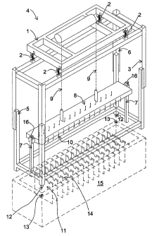
Figure 1 Transfer apparatus

In a lifting device 1 according to figure 1, there is suspended by rigging
screws
2 a stationary control housing 3. The rigging screws 2 are preferably short,
with
a length of 250 millimeters. Now, when using the structure according to the
invention, the control housing 3 advantageously attenuates the mass inertial
forces during horizontal acceleration and slow-down of the load. Thus, when
the lifting device 1 moves from tank to tank, the horizontal swinging of the
load
is prevented. The transfer apparatus 4 is shifted to the desired spot by
computer control. When necessary, the stationary control housing 3 can be
moved horizontally and turned around its central axis by means of the ball
joints
provided at both ends of the rigging screws. The movable controi frame 5
belonging to the transfer apparatus 4 is arranged to move essentially
vertically
along the slide surfaces 6 of the control frame. The control frame 5 is
provided
with vertical control shafts 7, along which a gripping element 8, such as a
spear, can be moved in the vertical direction by means of the control surfaces
16 of the spear. The control shafts 7 are arranged vertically on the opposite
sides of the control frame 5, and they are square in cross-section.
Advantageously the control shafts are placed so that during the lifting of the
control frame 5, they do not strike the lifting device 1 located above. From
above, the spear 8 hangs from the lifting device and is attached thereto by
ropes 9. Underneath the spear 8, there are provided gripping elements 10 such
as hooks, whereby the electrodes 11 are lifted from the tank or lowered
therein.
When the transfer apparatus 4 should be aligned at the right spot at the tank
15, the location is first programmed by using a computer. When the apparatus
is aligned at the right spot, the control frame 5 moving along the slide
surfaces


CA 02468964 2004-06-01
WO 03/053839 PCT/FI02/00962
6 of the control housing 3 is mechanically lowered down, and at the tanks the
conical pins 12 provided at least at two corners of the control frame are
inserted
in the holes 13 meant for the conical pins, while the rigging screws 2
allow'the
necessary horizontal and turning motion of the control housing 3 with respect
to
5 the lifting arrangement. In shape, the holes are either round or elongate,
and
their diameter is preferably 100 millimeters. Advantageously the holes can be
manufactured already when the tank is being made. Thereafter a gripping
element 8, such as a spear, is lowered down by means of wires, so that it
slides
supported by the control shafts of the control frame. The hooks provided in
the
spear are fastened to brackets 14 provided in the electrodes 11, and the
electrodes are lifted to a suitable height. Thereafter the control frame is
lifted
up, and the lifting device 1 transfers the electrodes 11 to the desired
position.

Representative Drawing
A single figure which represents the drawing illustrating the invention.
Administrative Status

For a clearer understanding of the status of the application/patent presented on this page, the site Disclaimer , as well as the definitions for Patent , Administrative Status , Maintenance Fee  and Payment History  should be consulted.

Administrative Status

Title Date
Forecasted Issue Date 2010-06-01
(86) PCT Filing Date 2002-11-29
(87) PCT Publication Date 2003-07-03
(85) National Entry 2004-06-01
Examination Requested 2007-08-21
(45) Issued 2010-06-01
Expired 2022-11-29

Abandonment History

There is no abandonment history.

Payment History

Fee Type Anniversary Year Due Date Amount Paid Paid Date
Registration of a document - section 124 $100.00 2004-06-01
Application Fee $400.00 2004-06-01
Maintenance Fee - Application - New Act 2 2004-11-29 $100.00 2004-06-01
Maintenance Fee - Application - New Act 3 2005-11-29 $100.00 2005-10-14
Maintenance Fee - Application - New Act 4 2006-11-29 $100.00 2006-10-26
Request for Examination $800.00 2007-08-21
Maintenance Fee - Application - New Act 5 2007-11-29 $200.00 2007-10-24
Maintenance Fee - Application - New Act 6 2008-12-01 $200.00 2008-10-22
Registration of a document - section 124 $100.00 2009-06-09
Maintenance Fee - Application - New Act 7 2009-11-30 $200.00 2009-10-26
Final Fee $300.00 2010-03-19
Maintenance Fee - Patent - New Act 8 2010-11-29 $200.00 2010-11-18
Maintenance Fee - Patent - New Act 9 2011-11-29 $200.00 2011-11-17
Maintenance Fee - Patent - New Act 10 2012-11-29 $250.00 2012-11-15
Maintenance Fee - Patent - New Act 11 2013-11-29 $250.00 2013-11-18
Maintenance Fee - Patent - New Act 12 2014-12-01 $250.00 2014-11-19
Maintenance Fee - Patent - New Act 13 2015-11-30 $250.00 2015-11-16
Maintenance Fee - Patent - New Act 14 2016-11-29 $250.00 2016-11-21
Maintenance Fee - Patent - New Act 15 2017-11-29 $450.00 2017-11-21
Maintenance Fee - Patent - New Act 16 2018-11-29 $450.00 2018-11-19
Maintenance Fee - Patent - New Act 17 2019-11-29 $450.00 2019-11-18
Maintenance Fee - Patent - New Act 18 2020-11-30 $450.00 2020-11-16
Owners on Record

Note: Records showing the ownership history in alphabetical order.

Current Owners on Record
OUTOTEC OYJ
Past Owners on Record
KIVISTO, TUOMO
MARTTILA, TOM
OUTOKUMPU OYJ
Past Owners that do not appear in the "Owners on Record" listing will appear in other documentation within the application.
Documents

To view selected files, please enter reCAPTCHA code :


To view images, click a link in the Document Description column. To download the documents, select one or more checkboxes in the first column and then click the "Download Selected in PDF format (Zip Archive)" or the "Download Selected as Single PDF" button.

List of published and non-published patent-specific documents on the CPD .

If you have any difficulty accessing content, you can call the Client Service Centre at 1-866-997-1936 or send them an e-mail at CIPO Client Service Centre.


Document
Description 
Date
(yyyy-mm-dd) 
Number of pages   Size of Image (KB) 
Abstract 2004-06-01 1 36
Claims 2004-06-01 3 109
Drawings 2004-06-01 1 44
Description 2004-06-01 5 261
Representative Drawing 2004-06-01 1 40
Claims 2009-07-29 2 73
Cover Page 2004-08-05 2 68
Description 2009-05-20 5 254
Abstract 2009-05-20 1 25
Claims 2009-05-20 2 68
Representative Drawing 2010-05-06 1 22
Cover Page 2010-05-06 2 64
PCT 2004-06-01 9 416
Assignment 2004-06-01 5 154
Prosecution-Amendment 2009-04-02 3 95
Prosecution-Amendment 2009-07-15 1 31
Assignment 2009-06-09 3 83
Prosecution-Amendment 2007-08-21 1 42
Prosecution-Amendment 2007-08-21 1 37
Correspondence 2010-03-19 2 68
Prosecution-Amendment 2009-05-20 8 369
Prosecution-Amendment 2009-07-29 4 152