Note: Descriptions are shown in the official language in which they were submitted.
CA 02469001 2004-06-02
WO 03/049598 PCT/US02/39169
BIOABSORBABLE SEALANT
BACKGROUND OF THE INVENTION
1. Field of the invention
This invention relates, generally, to the medical arts. More particularly, it
relates to means for sealing openings in a mammalian body created by any
means.
2. Description of the prior art
Openings may be formed in a human or other mammalian body by numerous
means. Needles or other medical instruments may create puncture or other types
of
openings, for example. Moreover, electrical, ultrasound, optical instruments
and the
like may create openings. Gunshot and knife wounds and numerous other events
may
also cause openings to be formed.
An opening in a lung is undesirable because air leaks therefrom and causes the
lung to collapse. However, openings in soft tissue, as well as openings in
internal
organs, such as the heart, kidney, liver, etc., also require closure. Openings
in bones,
cartilage, ligaments, and other hard tissue must also be closed.
Many techniques have been developed for the surgical closing of openings.
Sutures were invented long ago, for example. One important drawback to using
sutures in some applications arises from the fact that the needle used to sew
the suture
in place typically has a diameter that is larger than the suture. Thus, if a
suture is used
to close an opening in a lung, for example, air can escape from the lung in
the space
that surrounds the suture, i.e., the space has the diameter of the needle and
is not fully
occupied by the suture. This problem is addressed by applying an adhesive over
the
suture; when the adhesive cures, the openings around the suture are sealed.
However,
adhesives are difficult to apply and control and require time to cure.
Another more recently developed technique for closing openings includes the
use of staples. The force required to apply staples may result in torn tissue.
One
solution to this problem is to apply an adhesive over the staples to seal the
torn areas,
just as is done in connection with sutures.
Adhesive have been used to close other openings in the body as well.
3o Laparoscopic and endoscopic procedures, for example, may require
sophisticated
instrumentation. In situ curing of adhesives may be problematic depending upon
the
application, and may require the use of curing agents and other means for
cross-
linking free radicals to form the required bond. The curing agent may be air,
visible
CA 02469001 2004-06-02
WO 03/049598 PCT/US02/39169
light, ultraviolet light, heat, laser beains, chemical compounds that require
mixing
with one another, and so forth.
It would be advantageous therefore, if means for closing an opening could be
found that did not rely upon adhesives and curing agents.
Numerous medical procedures and even non-medical events can result in
openings in the body that need to be sealed, as mentioned earlier. Openings
inust be
closed not just to stop the escape of air from the lungs, but to also stop the
escape of
body fluids from other body parts. Sealing means for closing openings are
needed to
stop the flow of blood, cerebral spinal fluid, and other fluids.
For exemplary puiposes, an opening made by a biopsy needle will be
considered. In a biopsy procedure, a needle adapted to collect tissue is
inserted into a
suspected lesion, usually multiple times. When a sufficient quantity of the
lesion has
been collected, it is taken to a lab for analysis.
To perform the procedure, a coaxial needle is first inserted so that its
leading
end is positioned near the suspected lesion. A biopsy needle is then inserted
through
the coaxial needle.
The puncture opening made by the coaxial needle may close and heal naturally
if the lesion is in soft tissue such as a breast. However, if a lesion is in
the lung, the
puncture opening made by the coaxial needle may need to be closed quickly. The
use
of sutures or adhesives, or sutures and adhesives, are well-known as already
mentioned, but such techniques have limitations.
What is needed, then, is an apparatus for closing an opening in a lung or
other
vascular organ as well as in soft or hard tissue. The needed apparatus should
close an
opening quickly but should not cause problems of the type associated with
adhesives.
Physicians often have a need to re-visit a surgical procedure site to monitor
a
patient's recovery. However, the sutures and adhesives now in use include no
means
for helping a physician find the surgical site when a follow-up look is
desired.
Thus there is also a need for a means that would enable a surgeon to locate a
surgical site in the days, weeks, or months following a surgical procedure.
However, in view of the prior art considered as a whole at the time the
present
invention was made, it was not obvious to those of ordinary skill in the
pertinent art
how the identified needs could be fulfilled.
2
CA 02469001 2004-06-02
WO 03/049598 PCT/US02/39169
SUMMARY OF THE INVENTION
The long-standing but heretofore unfulfilled need for a method and apparatus
for sealing openings made by medical or non-medical procedures in a mammalian
body is now met by a new, useful, and nonobvious invention.
A first embodiment of the invention includes a plug formed of a preselected
bioabsorbable material that expands in response to a predetermined stimulus.
The
plug is sized to fit within the opening prior to application of the
predetermined
stimulus to the dehydrated plug. The plug expands upon application of the
predetermined stimulus thereto until the plug seals the opening. In this way,
the plug,
1o when expanded, prevents flow of liquid or gaseous fluid through the
opening. The
plug is gradually bioabsorbed as natural processes heal the opening. The
preselected
bioabsorbable material is a dehydrated hydrogel and the predetermined
stiinulus is
moisture that is naturally present in the mammalian body.
The plug may have a solid, cylindrical configuration prior to application of
the
predetermined stimulus thereto so that the plug is adapted to fit into a lumen
of a
needle to facilitate introduction of the plug into the opening.
If the plug is to be employed as a scaffold for tissue regeneration, it may be
provided in forms more suitable for that purpose. For example, it may have a
corkscrew configuration at one end. It may also be designed to provide a
mechanical
anchor as well, having a leading end that expands radially outwardly after
placement
to prevent unintended outward migration of the plug.
The plug is impregnated with a contrasting agent to facilitate detection of
the
plug by imaging means selected from the group of imaging means consisting of
magnetic resonance imaging, ultrasound, Doppler, and roentgenological means
including x-ray, CT scan, mammography, and fluoroscopy.
Alternatively, the plug includes a radioactive substance detectable by a
radiation detecting means including a gamma counter and a scintillation
counter. In
anotlier alternative, the plug includes a transmitting means adapted to
transmit signals
in the electromagnetic spectruin that are detectable by receivers adapted to
receive
signals in the electromagnetic spectrum.
The plug is adapted to be slideably disposed in a lumen of a needle. A plug
displacement means is adapted to abuttingly engage and slidingly displace the
plug
3
CA 02469001 2004-06-02
WO 03/049598 PCT/US02/39169
within the lumen to a preselected location near a distal end of the lumen.
Withdrawal
of the needle coupled with maintaining the plug displacement means at said
preselected location during the withdrawal results in placement of the plug at
the
preselected location. Withdrawal of the plug displacement means does not cause
displacement of the plug.
The novel material also has utility in promoting angiogenesis in a mammalian
heart. A cavity or bore is formed in a heart and growth factor means is
introduced into
the bore. A bioabsorbable plug that expands in response to a predetermined
stimulus
then plugs the bore. The predeternlined stimulus is applied to the
bioabsorbable plug
lo so that the bioabsorbable plug expands and seals the growth factor means
within the
bore.
The novel plug has further utility as a means for preventing loss of spinal
fluid
from the thecal sac. An opening is formed at a preselected site in the thecal
sac by a
biopsy needle introduced to the preselected site through a coaxial needle. The
biopsy
needle is withdrawn from the preselected site after the opening has been
formed. A
delivery catheter having a dehydrated, bioabsorbable plug formed of a
preselected
material that expands in response to a predetermined stimulus positioned in
its lumen
is then introduced through the coaxial needle to the preselected site. The
dehydrated,
bioabsorbable plug is pushed from the lumen of the catheter into the opening
and said
catheter is withdrawn from the preselected site. The bioabsorbable plug
expands upon
being hydrated by natural fluids present at the preselected site. The
expansion holds
the plug in place and further serves to prevent leakage of spinal fluid from
the
opening.
The novel material is not limited to plugs. For example, it may also be formed
into a cylindrical meinber that slideably receives a plug. Such a cylindrical
member
and a plug may be used with one another to provide a means for sealing an
incision in
an artery. More particularly, a guide wire is inserted through the incision
and a lumen
of an introducer sheath is placed in receiving relation to the guide wire so
that a
leading end of the introducer sheath is guided to the incision by the guide
wire. The
leading end of the introducer sheath is positioned into abutting and
surrounding
relation to the incision. A dehydrated, bioabsorbable tube formed of a
preselected
material that expands in response to a predetermined stimulus is pushed from a
lumen
4
CA 02469001 2004-06-02
WO 03/049598 PCT/US02/39169
of the introducer sheath so that a leading end of the dehydrated,
bioabsorbable tube is
disposed in abutting and surrounding relation to the incision. The guide wire
and the
introducer sheath are then withdrawn from the artery. The leading end of a
delivery
catheter having an external diameter less than an internal diameter of the
dehydrated,
bioabsorbable tube is then introduced into the lumen of the dehydrated,
bioabsorbable
tube. A dehydrated, bioabsorbable plug formed of a preselected material that
expands
in response to a predetennined stimulus is positioned in a lumen of the
delivery
catheter and is pushed from said lumen into the lumen of the dehydrated,
bioabsorbable tube. The delivery catheter is withdrawn and the dehydrated,
bioabsorbable plug expands within the lumen of the dehydrated, bioabsorbable
tube
when contacted by natural moisture within the blood flowing through the
artery. The
dehydrated, bioabsorbable tube expands when contacted by the natural moisture
within the blood and by natural moisture within tissue that surrounds the
artery.
In another embodiment, an elongate suture is formed of a preselected
bioabsorbable material that expands in response to a predetermined stimulus.
The
elongate suture is adapted to be pulled by a needle so that the elongate
suture is used
to sew closed the opening. The elongate suture has a diameter slightly less
than a
diameter of the needle, there being a clearance space about the elongate
suture equal
in diameter to the diameter of the needle less the diameter of the elongate
suture. The
elongate suture expands upon application of the predetermined stimulus thereto
until
the elongate suture seals the clearance space. The elongate suture, when
expanded,
prevents flow of liquid or gaseous fluid through the clearance space and is
gradually
bioabsorbed as the opening is healed by natural processes. The preselected
bioabsorbable material is a hydrogel and the predetermined stimulus is
moisture that
is naturally present in a mammalian body. The elongate suture may be
impregnated
with a contrasting agent to facilitate its detection by imaging means selected
from the
group of imaging means consisting of magnetic resonance imaging, ultrasound,
Doppler, and roentgenological means including x-ray, CT scan, mammography, and
fluoroscopy. The elongate suture may include a radioactive substance
detectable by a
radiation detecting means including a gamma counter and a scintillation
counter.
Alternatively, it may include a transmitting means adapted to transmit signals
in the
electromagnetic spectrum that are detectable by receivers adapted to receive
signals in
5
CA 02469001 2007-05-24
WO 031049598 PCTIU502139169
the electromagnetic spectrunt. Moreover, the elongate suture may be hollow and
filled
with a gaseous fluid.
A conventional sut-ur.e, both bioabsorbable and nonbioabsorbable, may be
coated with a material that expands in response to a predeteniiined stunulus
and used
in the same way as the sutlire made entirely of the novel material. This type
of coating
also provides a lubr.icious surface having a low coefficient of friction to
minim.ize
trauma during the suturing process.
A rigid medical staple of the type used in anastomosis of organs may also be
coated with a preselected bioabsorbable material that expands in response to a
lo predetermined stiniulus to fill the openings made by the stapling
procedure.
An important aspect of this invention is to provide a nieans for sealing
openings in a mammalian body quickly and in the absence of conventional
sutures,
staples, and adhesives.
Another aspect is to provide a bioabsorbable nieans for sealing such openings.
Another major aspect is to provide a nlarking means that enables a physician
to easily find a surgical site for follow-up purposes.
These and other important apsects, advantages, and features of the invention
will become clear as this description pruceeds.
The iulvention accordingly comprises the features of construction, combination
2o of elements, and arrangement of parts that Svill be exemplified in the
description set
forth hereinafter and the scope of the invention will be indicated in the
claims.
6
CA 02469001 2007-05-24
WO 03J0-49598 PCT/i1S02/39169
BRIEF DESCRIPTION OF THE DRAWINGS
For a fuller understanding of the nature and aspects of the invention,
reference
should be made to the following detailed description, taken in connection with
the
accompanying diagrammatic drawings, in which:
s Fig. 1 is a side elevational view of a biopsy needle taking a sample from a
lesion in a lung or any other soft tissue;
Fig. 2 is a .ew depicting the positioning of a bioabsorbable plug in th.e
coaxial needle of Fig. 1;
Fig. 3 is a view like that of Fig. 2, but after the coaxial needle has been
withdrawn, leaving the bioabsorbable plug in sealing relation to a puncture
wound;
Fig. 4 is a view like that of Fig. 3, but depicting the plug in its enlarged
configuration;
Fig. 5 is a view of an alternafive embodiment where the bioabsorbable seal is
positioned on an inside surface of a lung;
is Fig. 6 is a view of an alternative embodiment where the bioabsorbable seal
is
positioned on an outside su.rface of a lung;
Fig. 7A is a longitudinal sectional view of a tubular plug;
Fig. 7B is a longitudinal sectional view of a plug having an enlarged leading
end;
Fig. 7C is a longitudinai sectional view of a plug that may be used as a
"scaffold ' for therapeutic drugs or the like;
Fig. 7D is a longitudinal sectional view of another plug eonhguration having
utility as a scaffold;
Fig. 7F is a longitudinal sectional vieiv of another plug configuration having
utility as a scaffold;
Fig. 7F is a longitudinal sectional view of another plug configaration having
utility as a scaffold;
Fig. 7G is a longitudinal sectional view of another plug configuration having
utility as a scaffold;
Fig. 7H is a view of an alternative, hollow bioabsorbable plug;
Fig. 8A is a view of a bioabsorbable suture in isolation;
Fig. 8B is a view of a bioabsorbable suture in use to close an incision;
7
CA 02469001 2004-06-02
WO 03/049598 PCT/US02/39169
Fig. 9A is a view depicting the formation of a blind bore or core in the
myocardium of a mammalian heart;
Fig. 9B is a view depicting the injection of growth factors into the blind
bore;
Fig. 9C is a view depicting the delivery of a bioabsorbable seal to the biopsy
site;
Fig. 9D depicts the bioabsorbable seal in sealing relation to the growth
factor;
Fig. 9E depicts a plurality of blind bores filled with growth factor and
sealed
with the bioabsorbable plugs of this invention;
Fig. 9F depicts the formation of a cavity in the interior surface of the
myocardium;
Fig. 9G depicts the plugging of the cavity of Fig. 9F with the novel
bioabsorbable seal so that growth factor is sealed therein;
Fig. 1OA is a diagrammatic view depicting puncturing of the thecal sac to
withdraw cerebral spinal fluid;
Fig. 1OB is a similar view depicting the delivery of a dehydrated plug to the
puncture site;
Fig. lOC depicts the hydrated plug in closing relation to the puncture formed
in the thecal sac;
Fig. 1 1A is the first view in a series of animations depicting the first step
of a
method where an embodiment of the novel plug is used to seal an incision
fonned in
an artery;
Fig. 11B is the second view in said series of animations;
Fig. 1 1C is the third view in said series of animations;
Fig. 11D is the fourth view in said series of animations;
Fig. 11E is the fifth and final view in said series of animations;
Fig. 12A is a front elevational view of a staple coated with the novel
expandable and bioabsorbable material;
Fig. 12B is a front elevational view of the staple of Fig. 12A after
activation;
Fig. 12C is a sectional view depicting tissue on opposite sides of an incision
joined to one another by the novel staple;
Fig. 13A is a diagrammatic view of a cavity fomied in tissue being filled with
the novel dehydrated bioabsorbable polymers of this invention;
8
CA 02469001 2004-06-02
WO 03/049598 PCT/US02/39169
Fig. 13B is a diagrammatic view depicting the cavity filled by the expanded
polymers;
Fig. 14A is a diagrammatic view of an aneurysm being filled witli the novel
dehydrated bioabsorbable polymers of this invention;
Fig. 14B is a diagrammatic view depicting the aneurysm filled by the
expanded polymers;
Fig. 15A diagrammatically depicts a hole in a septum of a mammalian heart;
Fig. 15B is the first diagram in a four series animation depicting the novel
steps for sealing said hole;
Fig. 15C is the second diagram in said series of animations;
Fig. 15D is the third diagram of said series; and
Fig. 15E is the fourth diagram of said series.
DETAILED DESCRIPTION OF THE PREFERRED EMBODIMENT
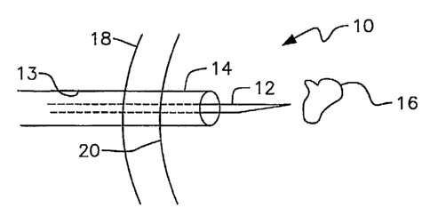
Referring to Fig. 1, it will there be seen that the reference numeral 10
denotes
a biopsy site as a whole. Openings in a mammalian body may be formed by
numerous
other medical procedures and non-medical events as mentioned earlier. A biopsy
procedure is explained just for exeniplary purposes.
A biopsy needle 12 is ensleeved within lumen 13 of coaxial needle 14 when
taking biopsy samples from lesion 16 because multiple entries and withdrawals
of
2o biopsy needle 12 are normally required. In the absence of coaxial needle
14, biopsy
needle 12 would have to make multiple punctures of the patient's skin and lung
during a biopsy procedure. Although coaxial needle 14 has a slightly larger
diameter
than biopsy needle 12, the trauma caused by one insertion of said coaxial
needle is
less than that of multiple biopsy needle insertions.
Tn the example if Fig. 1, the patient's skin is denoted 18 and the surface of
the
patient's lung is denoted 20. It should be understood, however, that the
utility of this
invention is not restricted to sealing openings formed in lungs by biopsy
procedures
but includes the sealing of openings formed by any means in the heart, brain,
liver,
kidneys, and even in hard tissue such as bone, cartilage, and the like.
When a sufficient amount of biopsy samples have been taken, biopsy needle
12 is withdrawn from coaxial needle 14.
9
CA 02469001 2004-06-02
WO 03/049598 PCT/US02/39169
As depicted in Fig. 2, a pusher assembly that includes a circular disc 24 and
a
rod 26 then slidingly introduces dehydrated plug 22 into lumen 13 of coaxial
needle
14. In this first-described embodiment, plug 22 is of solid cylindrical
construction, is
about 2.5 cm in length, and is positioned approximately as shown in Fig. 2,
i.e., a
small extent of the plug is external to surface 20 of the lung and a larger
extent thereof
is inside the lung. This particular positioning is not critical and is
depicted just to
indicate that plug 22 is preferably a relatively long cylindrical plug, in
this particular
application, so that. it is relatively easy to position in sealing relation to
the puncture
opening. The elongate extent of plug 22 provides a generous margin of error.
Fig. 3 depicts biopsy site 10 after withdrawal of coaxial needle 14. Pusher
disc
24 and rod 26 (Fig. 2) are held in place when coaxial tube 14 is withdrawn to
ensure
that plug 22 does not move. After coaxial tube 14 is fully withdrawn, pusher
disc 24
and rod 26 are withdrawn to produce the view of Fig. 3.
Plug 22 is formed of a material that expands upon contact with a stimulant
such as water, blood, air, visible light or other electromagnetic radiation
such as a
laser beam, a preselected chemical, and so on. In a preferred embodiment, the
stimulant is moisture which is naturally present on the surface of a patient's
lungs or
other soft tissue, internal organs, or the like.
Fig. 4 depicts plug 22 shortly after its installation. It has been in contact
with
moisture, or other predetermined stimulant, for a few moments and the
expandable
material has expanded. The expansion effectively seals the peripheral edge of
the
puncture opening and prevents air from escaping the lungs. In other
applications, the
plug is used to stop bleeding or other liquid fluid flow from the liver,
heart, thecal sac,
etc.
An alternative embodiment is depicted in Fig. 5. In this embodiment,
bioabsorbable element 22a is releasably secured to the distal end of rod 28.
Element
22a is disk-shaped, having less longitudinal extent than bioabsorbable plug 22
of the
first embodiment. Plug 22a has an unexpanded diameter that is preferably
slightly
greater than that of plug 22 so that it deploys to a diameter that is at least
slightly
greater than the diameter of the puncture wound when coaxial rod 14, not shown
in
Fig. 5, is retracted. Rod 28 is then retracted and separated from plug 22a
when said
plug 22a is firmly positioned in sealing relation to the inner wall of lung
20.
CA 02469001 2004-06-02
WO 03/049598 PCT/US02/39169
There are numerous means for interconnecting rod 28 and plug 22a such that
said rod may be separated from plug 22a when said plug is firmly positioned in
sealing relation to the puncture opening. An adhesive having a predetermined
strength
may be used, for example, and separation would occur upon applying a torque to
rod
28 about its longitudinal axis.
Another alternative embodiment is depicted in Fig. 6. This embodiment is
much like the embodiment of Fig. 5 except that plug 22a is positioned in
firmly
sealing relation to the puncture opening on the exterior surface of the lung
prior to
separation of plug 22a and rod 28.
Figs. 7A-H depict a few of the possible variations of plug 22. All of these
plugs are in a dehydrated condition when positioned within lumen 13 of coaxial
needle 14 and are expanded by contact with the body's natural moisture or by
other
means as mentioned earlier upon being pushed from said lumen by the earlier-
mentioned pusher assembly.
In Fig. 7A, plug 22 is of tubular construction. This plug would not have
utility
in sealing an opening in a lung, obviously.
. Plug 22 of Fig. 7B has an enlarged anchor member 22b at its leading end.
Anchor member 22b is compressed when plug is within lumen 13 and expands at
least
to some extent under its own bias upon emergence from said coaxial needle.
Plug 22 of Fig. 7C is generally "U"-shaped when seen in longitudinal cross-
section as in said Fig. 7C.
Plug 22 of Fig. 7D has a structure similar to that of Fig. 7C but further
includes an outwardly turned flange 22c at its leading end. Flange 22c
performs the
same function as anchor member 22b of Fig. 7B, i.e. it prevents longitudinal
travel of
the plug in a direction toward the surface of the body, it being understood
that the
flange or anchor member is positioned in abutting relation to an interior side
of an
opening formed in an organ or other tissue.
Plug 22 of Fig. 7E has an irregular or corkscrew leading end. Fig. 7F depicts
a
plug having a leading end in the configuration of a tapered corkscrew. Plug 22
of Fig.
3o 7G includes a medal part of irregular configuration flanked by a leading
and a trailing
end of solid cylindrical configuration.
11
CA 02469001 2004-06-02
WO 03/049598 PCT/US02/39169
Significantly, the embodiments of Figs. 7C-G enable plug 22 to serve as a
"scaffold" upon which may be deposited growth hormone, stem cells, therapeutic
drugs or any type, and so on. The increased surface area provides means for
holding
such therapeutic elements.
Plug 22 or 22a may have a solid or hollow construction. The embodiment 22b
of Fig. 7H is hollow and is filled with a gaseous fluid either just before or
just after it
is positioned in sealing relation to a puncture opening. The gaseous fluid is
introduced
into the hollow interior of plug 22b through rod 30, said rod being in fluid
communication with balloon-like neck 22c of plug 22b. Plug 22V is expanded by
gas
introduction until it firmly seals the opening. Neck 22c is then sealed by any
suitable
means.
Alternatively, plug 22b is filled with a gaseous fluid prior to its use and
neck
22c is sealed prior to introduction of the plug.
It should be understood that the lung is not the only internal organ of the
body
that may be punctured by a needle or other medical or non-medical device and
require
sealing. Openings formed in any vascular organs such as the kidneys, the
liver, the
heart, the brain, and the stomach, for example, may be sealed with the novel
apparatus. Nor is the invention limited to the sealing of vascular organs. For
example,
it may be used to seal an opening formed in the thecal sac. The novel
apparatus has
utility in sealing openings formed by any means in any mammalian soft or hard
tissue.
It may also be used to seal surgical sites of the type created during
arthroscopic, endoscopic, or laporoscopic procedures conducted on the knee,
back,
and neck, for example. The diameter of the expandable, bioabsorbable plug
would be
increased as required to fill the trocar or other device that performs the
role of a
coaxial needle.
As an additional example, the novel plug may be employed to seal an incision
of a femoral artery.
Plug 22 is formed of a bioabsorbable material so that it is bioabsorbed by the
body as the opening heals. Since people heal at different rates, a
bioabsorbable
material should be selected so that it is fully bioabsorbed in a period of
time such as a
few weeks to a few months.
12
CA 02469001 2004-06-02
WO 03/049598 PCT/US02/39169
Examples of suitable bioabsorbable materials that expand when contacted by
water include hydrogels, collagen, polysalactic acid, and any other suitable
hydrophilic agents.
Examples of polymers that swell in the presence of aqueous fluids such as
biological fluids will now be disclosed. Virtually all of the following
polymers are
hydrogels. Synthetic hydrogels can be prepared from the following classes of
polymers and these are generally considered to be non-biodegradable:
poly(hydroxyalkyl methylacrylates) such as poly(glyceryl methacrylate)
poly(acrylamide) and poly(methacrylamide) and derivatives
poly(N-vinyl-2-pyrrolidone)
anionic and cationic hydrogels
poly(vinyl alcohol)
poly(ethylene glycol) diacrylate and derivatives from block copolymers
composed of poly(ethylene oxide)-poly(propylene oxide)-poly(ethylene oxide)
and
poly(propylene oxide)-poly(ethylene oxide)-poly(propylene oxide) blocks,
respectively;
All of the above can be cross-linked with agents such as ethylene glycol
dimethacrylate or methylene-bis-acrylamide.
Biodegradable synthetic hydrogels can be prepared from polymers such as
those listed above by incorporating one or more of the following monomers:
Glycolide, Lactide, e-Caprolactone, p-Dioxanone and Trimethylene Carbonate
In addition, biodegradable hydrogels can be based on natural products such as
the following:
Polypeptides such gelatin which may be cross-linked with formaldehyde or
glutaraldehyde and various other dialdehydes.
Modified chitin hydrogels, which may be prepared from partially N-
deacetylated chitin which, may then be cross-linked with agents such as
glutaraldehyde.
Dextran, a polysaccharide, can be derivatized with groups such as 3-acryloyl-
3o 2-hydroxypropyl esters and subsequently cross-linked by free radical
copolymerization with N',N' -methylenebisacrylamide.
13
CA 02469001 2004-06-02
WO 03/049598 PCT/US02/39169
Starch may be similarly derivatized or using glycidyl acrylate followed by
free
radical cross-linking as described above.
The novel plug is also treated so that it is visible under fluoroscopy,
ultrasound, X-ray, magnetic resonance imaging, computed axial tomography (CAT)
scanning, and other imaging techniques. Accordingly, it may contain or be
impregnated with a contrast solution containing radium, iodine, beryllium, or
other
contrasting agent.
The bioabsorbable material of this invention could also be fabricated in a
thread-like forin and used as a suture material. Alternatively, after a suture
has been
1o made using conventional suture material, the bioabsorbable material could
be
topically applied to the sutured area to help seal the punctures made by the
suture.
Fig. 8A depicts an elongate thread of suture material 32 formed of the novel
dehydrated hydrogel material of this invention and Fig. 8B depicts said suture
material 32 in use to close an incision formed in tissue 33.
In a first suture embodiment, suture material 32 is formed entirely of the
dehydrated hydrogels of this invention. When suture material 32 comes into
contact
with tissue, the natural moisture within the tissue causes material 32 to
expand and
seal the hole created by the needle, it being understood that the needle has a
diameter
greater than that of the suture material 32. The body heals as the
bioabsorbable suture
is absorbed and no suture material remains after the holes have completely
closed as a
result of natural healing.
In a second embodiment, regular PGA/PLA sutures or even non-bioabsorbable
sutures are coated with the novel suture material, i.e., extensible type
polymers such
as hydrogel that have been dehydrated. Figs. 8A and 8B should also be
interpreted as
depicting this second embodiment. The coating expands upon contact with the
moisture in the tissue. The non-bioabsorbable suture underlying the
bioabsorbable
suture material will remain, of course, after the bioabsorbable material has
been
absorbed but the body's natural healing process will have sealed the holes
around the
suture. Where a regular PGA/PLA suture is coated, it too will bioabsorb as the
coating
is bioabsorbed.
Advantageously, the body's natural moisture, in most applications, will cause
the suture or the suture coating to expand to fill the space around it created
by the
14
CA 02469001 2004-06-02
WO 03/049598 PCT/US02/39169
larger diaineter of the needle. This eliminates the need to apply an adhesive
over the
sutures and thus eliminates the step of curing the adhesive.
Figs. 9A - 9G disclose how the novel plugs can be used to fill cavities formed
in heart tissue to promote angiogenesis in heart patients. Growth factor, stem
cells, or
the like are placed in the cavities or blind bores and sealed therein by means
of the
novel plugs disclosed herein. In Fig. 9A, coaxial needle 40 is depicted in
penetrating
relation to epicardium 42 and myocardium 44. Endocardium 46 is not penetrated
to
avoid puncturing left ventricle 48 of heart 50 in this particular example.
Biopsy needle
52 is inserted through the lumen of coaxial needle 40 to remove a core of
tissue from
lo myocardium 44. This creates a blind bore in myocardium 44.
Biopsy needle 52 is then removed from the lumen of coaxial needle 40 and a
delivery sheath 54 is inserted into the lumen of said coaxial needle as
depicted in Fig.
9B. Growth factor 55 such as vascular endothelial growth factor, stem cells,
or the
like are pushed into the blind bore from the lumen of delivery sheath 54 by
plunger
56.
Plunger 56 is then momentarily withdrawn from the lunlen of delivery sheath
54 and a dehydrated bioabsorbable plug 22d is inserted into said lumen.
Plunger 56 is
then retrieved to push plug 22d into sealing relation to the blind bore as
indicated in
Fig. 9C.
Fig. 9D depicts plug 22d in said sealing relation. Growth factor 55 deposited
into the bottom of the blind bore is sealed therein by bioabsorbable plug 22d.
Plug
22d is hydrated by the natural moisture or body, fluids of the myocardium and
in Fig.
9D has expanded to tightly seal the blind bore so that growth factor 55 cannot
leak
therefrom.
Fig. 9E depicts multiple blind bore sites filled with growth factor 55 and
sealed by plugs 22d. Growth factor 55 promotes angiogenesis so that newly
formed
blood vessels can perform the function of dead or damaged blood vessels
throughout
the damaged region of the heart. Exterior surface 23 of each plug 22d is
hydrophillic
so that pericardium tissue does not attach to the biopsied site.
The blind bores or cavities can also be formed in the interior surface of the
myocardium as depicted in Figs. 9F and 9G. Cavity 53 in Fig. 9F is formed in
endocardium 46 by a biopsy gun or other suitable instrument and filled with
growth
CA 02469001 2004-06-02
WO 03/049598 PCT/US02/39169
factor. Epicardium 42 is not punctured in this embodiment. Dehydrated
bioabsorbable
plug 22d is then slid into sealing relation to cavity 53 by a suitable plunger
means to
create the structure seen in Fig. 9G. Damaged heart tissue in the vicinity of
cavity 53
is then regenerated by neovascularization. Multiple cavities 53 can be formed
in the
interior side of myocardium 44 as needed.
Fig. l0A depicts coaxial needle 40 that receives the needle of syringe 58 used
to withdraw spinal fluid 59 from spinal cord 60. Neck muscle is denoted 61.
Syringe 58 is then withdrawn and as indicated in Fig. lOB, dehydrated
bioabsorbable plug 22d is pushed from the lumen of delivery catheter 54 by
plunger
56 into sealing relation with the opening made by the needle of syringe 58.
Fig. lOC depicts bioabsorbable plug 22d in sealing relation to the opening
made by said needle. Said plug 22d is in its expanded configuration due to the
natural
moisture provided by spinal fluid 59, spinal cord 60, and neck muscles 61.
Figs. 11A - 11 E depict how a plug of this invention may be employed to seal
an incision made in an artery.
In Fig. 11A, guide wire 70 is depicted inserted into femoral or other artery
72
through incision 71, which may be made for diagnostic or intervention
purposes.
After the primary diagnostic or intervention procedures have been performed,
the
instruments used are removed but guide wire 70 is left in position so that it
may be
used as follows. Leading end 74a of introducer sheath 74 is positioned in
abutting
relation to artery 72 and in surrounding relation to incision 71. Reference
numeral 73
denotes fat and 75 is the skin surface.
A dehydrated bioabsorbable material 22e in the form of a tube is then
introduced through lumen 76 of introducer sheath 74 so that its leading end
also abuts
artery 72 in surrounding relation to incision 71, as depicted in Fig. 11 B.
Introducer sheath 74 is then withdrawn, leaving tube 22e in encircling
relation
to incision 71 as depicted in Fig. 11 C.
Guide wire 70 is then removed. As indicated in Fig. 11D, an introducer sheath
80 having a smaller external diameter than introducer sheath 74 of Fig. 11B,
is
employed to position dehydrated plug 22f in plugging relation to tube 22e.
Specifically, plug 22f is disposed in lumen 81of introducer sheath 80 and the
leading
end of said introducer sheath 80 is slideably inserted into the trailing end
of tube 22e
16
CA 02469001 2004-06-02
WO 03/049598 PCT/US02/39169
as depicted. Plunger 82 is then employed to push plug 22f into tube 22e. Note
that
plug 22f need not abut incision 71 to accomplish its sealing function.
Fig. 11E depicts tube 22e and plug 22f after withdrawal of introducer sheath
80 and plunger 82. Both tube 22e and plug 22f are now hydrated by the natural
moisture of the body. Accordingly, both have expanded and are held in place by
fat
23 and by each other. Moreover, the moisture content of the blood flowing
through
the artery also serves to cause the expansion of tube 22e and plug 22f.
Incision 71 will
heal gradually and tube 22e and plug 22f will be bioabsorbed over time. The
trailing
end of tube 22e that projects upwardly from the surface of skin 75 may be
trimmed so
1o that it is flush with said skin or slightly countersunk with relation
thereto.
Figs. 12A-C depict the use of the novel material in the context of staples.
Conventional, nonbioabsorbable staples are often used to close incisions. The
staples
of this embodiment are used in end-end and end-side anastomosis of organs such
as
the lung, the bowel, and the like. Fig. 12A depicts a staple 90 before it has
been used
and Fig. 12B depicts said staple 90 after activation. Fig. 12C depicts said
staple when
holding together two pieces of tissue 91 and 92 separated by incision 93. This
embodiment requires the use of the novel material as a coating over a
conventional
staple because the conventional staple provides the required stiffness to
enable the
staple to punch through tissue layers 91, 92. The coating then expands to seal
the
2o holes created by the staple and the holes heal gradually as the
bioabsorbable coating is
bioabsorbed.
From the foregoing, it is apparent that the novel method includes the steps of
sealing an opening of the type made by a needle or other medical or non-
medical
instrument by providing a plug formed of a bioabsorbable material that expands
in
response to a predetermined stimulus. The plug may be positioned within the
lumen
of a needle, a delivery sheath, or the like, and pushed therefrom by a
suitable pushing
means or it may installed by any other suitable method. The particular method
of
installation depends upon the type of opening being plugged and the particular
method of application is not critical to this invention. In an exemplary
embodiment
involving a needle, the plug is slidingly displaced by a plunger means to a
preselected
location near a distal end of the lumen of the needle. Withdrawal of the
needle
coupled with maintaining the plug at the preselected location results in
placement of
17
CA 02469001 2004-06-02
WO 03/049598 PCT/US02/39169
the plug at the preselected location. The predetermined stimulus is then
applied to
cause expansion of the plug and sealing of the opening made by the needle.
Where the novel material is formed into a thread-like form for use as a suture
material, or as a coating for conventional suture material which or may not be
bioabsorbable, the novel method includes the steps of sewing an opening in
accordance with acceptable medical procedure. In most applications, the
natural
moisture of the body will then cause the suture or the coating to expand
radially and
to thereby fill the space around it created by the larger diameter of the
needle. Where
insufficient moisture is present, it can simply be brushed or sprayed on in
the form of
1o a saline solution, for example. As mentioned earlier, other activating
agents other than
moisture are also within the scope of this invention.
Where the novel material is used as a coating for conventional staples, the
novel method includes the step of using the coated staples in accordance with
acceptable medical practice. The coating expands to fill openings or holes
created by
the staples and said coating is bioabsorbed as the opening heals.
The novel expandable polymers also have utility in filling cavities in tissue.
For example, as depicted in Fig. 13A, a cavity 100 may be formed in tissue 102
such
as a liver or other organ when a tumor or lesion is removed. Catheter 104 is
introduced to the site and a plurality of dehydrated plugs 22 of the novel
material are
pushed into cavity 100. As depicted in Fig. 13B, plugs 22 expand upon contact
with
naturally present moisture and fill the cavity. This prevents infections or
other
complications that may arise if the cavity is left unfilled.
As another example, novels plugs 22 may also be used to fill a space created
by an aneurysm. In Fig. 14A, aneurysm 106 has formed a pocket adjacent artery
108.
Catheter 110 is introduced into aneurysm 106 tlirough artery 108 and a
plurality of the
novel plugs 22 in dehydrated condition are pushed into the aneurysm. As
indicated in
Fig. 14B, available natural moisture causes expansion of plugs 22 and the
cavity left
behind by the aneurysm is filled.
It is therefore understood that the novel plugs have utility not just in
3o applications where an opening has been formed in the surface of tissue, but
in filling
cavities or other pockets within tissue as well, without regard to the cause
of the
cavity or pocket.
18
CA 02469001 2004-06-02
WO 03/049598 PCT/US02/39169
It should also be understood that there are applications where waiting for
natural body fluids to activate the dehydrated plug or plugs may be
contraindicated. In
those applications, saline or other suitable source of moisture is injected
into the
lumen of the needle or catheter of other plug-delivery device before the plug
is pushed
therefrom and deposited into an opening or cavity. In this way, hydration of
the plug
begins while the plug is still undeployed so that the time required for full
expansion
after the plug has left the delivery device is reduced or even eliminated.
Yet another application for the novel expandable, bioabsorbable materials is
in
the patching of a hole or holes in a mammalian heart. In the example of Fig.
15A, a
hole 120 in septum 122 unacceptably provides fluid communication between right
atrium 124 and left atrium 126. As indicated in Fig. 15B, guide wire 70 is fed
through
femoral vein 128 so that the distal free end of guide wire 70 passes though
hole 120 in
septum 122 and enters into left atrium 126. A delivery catheter or sheath 130
is then
fed over the guide wire until the distal free end of the sheath is also
positioned within
left atrium 126.
Guide wire 70 is then removed as indicated in Fig. 15C. Plug 22 is then
pushed from the lumen of sheath 130, by holding it in place with a plunger
while
slightly withdrawing sheath 130, until the distal free end of the plug is
positioned
within the left atrium. Plug 22 is allowed to expand upon contact with natural
moisture in the heart. It may also be pre-hydrated by injecting saline or
other suitable
solution into the lumen of sheath 130 prior to deployment of plug 22 so that
the
expansion time is feduced or eliminated. The expansion of plug 22 in left
atrium 126
provides an anchoring means so that sheath 130 can be slowly withdrawn,
leaving
plug 22 deployed in opening 120.
Sheath 130 is then witlidrawn fiu-ther as depicted in Fig. 15D so that plug 22
begins expanding in right atrium 124. Sheath 130 is then fully withdrawn as
depicted
in Fig. 15E. Plug 22 is now fully expanded and hole 120 is closed so that the
left and
right atriums are no longer in fluid communication witli one another.
Plug 22 is coated or impregnated with a contrasting agent to facilitate its
viewing and hence accurate placement when employing various imaging
techniques,
as in the embodiments described above.
19
CA 02469001 2004-06-02
WO 03/049598 PCT/US02/39169
A plug used to seal an opening in a heart is preferably formed of a material
that is bioabsorbed very slowly over a long period of time. Plug 22 may also
be
impregnated with a growth factor or other therapeutic agents to promote
healing.
It will thus be seen that the objects set forth above, and those made apparent
from the foregoing description, are efficiently attained. Since certain
changes may be
made in the above construction without departing from the scope of the
invention, it is
intended that all matters contained in the foregoing description or shown in
the
accompanying drawings shall be interpreted as illustrative and not in a
limiting sense.
It is also to be understood that the following claims are intended to cover
all of
l0 the generic and specific features of the invention herein described, and
all statements
of the scope of the invention that, as a matter of language, might be said to
fall
therebetween.
Now that the invention has been described,