Note: Descriptions are shown in the official language in which they were submitted.
CA 02469121 2004-05-28
1
Horizontal Omni-directional Windmill
Field of Invention
This invention relates to horizontally rotating windmills of the type in which
a rotor is
mounted on a vertical axle and drive shaft, and in which vertically disposed
vanes
are positioned so as to conduct airflow through the rotor.
Background of the Invention
Windmills and wind turbines are well known in the art. Windmills traditionally
include
a plurality of blades or vanes connected to a rotatable shaft. Wind (or other
fluids)
act upon the blades to create an aerodynamic or hydrodynamic reaction upon the
blades causing the shaft and blades to rotate about the axis of the shaft.
Windmills
have traditionally been employed across the world to perform functions from
pumping of water, grinding grains and with respect to changing kinetic energy
to
electrical energy, being coupled to other devices for generating and
transmitting
electrical power. In recent times, due to rising energy costs and awareness of
the
need for alternative energy sources, interest has greatly increased in devices
adapted to capture the power of the wind.
Examples of the prior art include U.S. 5,126,584 to Ouellet, U.S. 4,926,061 to
Arreola and U.S. 4,047,834 to Magoveny et al. U.S. 5,126,584 illustrates a
windmill
including moveable vanes, the vanes being formed of an outer stationary
shutter
and an inner moveable shutter. U.S. 4,926,061 illustrates a wind trap energy
system, each wind trap having a pair of vanes 60 degrees apart from the other
for
interception of wind kinetic energy from any direction. U.S. 4,047,834 to
Magoveny
et al., discloses a windmill having fixed vanes on an outer perimeter of a
fixed base
member and a plurality of fixed buckets mounted to a rotor mounted on an axle.
While these references generally disclose windmills of the type contemplated
by the
present invention, these references do not teach the geometry of the curved,
CA 02469121 2004-05-28
2
adjustable blades having a wing shaped configuration of the present invention.
Accordingly, there is a need for a relatively simple, inexpensive windmill
with
vertically oriented blades capable of being positioned at various angles.
Summary of the Invention
According to one aspect of the present invention, there is provided a
horizontal
omni-directional windmill comprising a rotor including an upper platform and a
lower
platform, a plurality of variable angle identically configured blades, wherein
each of
the blades is of a substantially aerodynamic configuration, each of the blades
being
oriented at a broad angle relative to the radius of the rotor, the blades
being oriented
in a generally vertical orientation relative to the upper and tower platforms.
According to a further aspect of the present invention, the horizontal omni-
directional
windmill is rotatable about its vertical axis, and also includes means for
coupling the
rotor to a power generator, the means including a power transfer shaft .
According to another aspect of the present invention, the horizontal omni-
directional
windmill includes blades having an angular orientation selected between about
20°
and about 50°, between about 35° and about 45°, and
desirably about 40°.
Brief Description of the Drawings
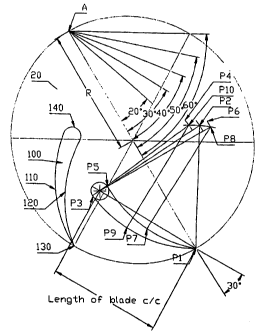
Figure 1 is an elevational view of the windmill of a first preferred
embodiment
illustrating the various angles and radii aspects of the present invention
Figure 2 is an exploded view of some of the parts being removed for simplicity
of the illustrations;
Figure 3 is a top view of the lower platform including a profile blade thereon
positioned at approximately 40 degrees to the radius;
CA 02469121 2004-05-28
3
Figure 4 is a top view of the lower platform including 6 profile blades
positioned
at approximately 40 degrees and their relative position to each other;
Figure 5 is an elevational side view of the windmill including the upper
platform,
and
Figure 6 is a side view of the present invention mounted on a support member.
Detailed Description of the Preferred Embodiments
With reference to the drawing figures, there is illustrated a preferred form
of a
rotatable windmill or wind turbine depicted generally by reference numeral 10.
The
windmill or wind turbine as illustrated includes a rotatable housing or rotor
10,
defined by spaced apart lower and upper discs or platforms 20 and 30
respectively,
blade or vane mounting means 40, rotatable axle means 50, and a plurality of
variable angle, aerodynamic vanes or profile blades 100. Figure 2 illustrates
a
disassembled view of the windmill 10, including upper and lower platforms 20
and 30
and vanes 100.
As illustrated in Figures 1 to 6, and more particularly in Figures 5 and 6, a
rotatable
housing or rotor 10 includes lower and upper horizontally-disposed discs or
platforms (20, 30) connected by the plurality of variable angle profile blades
100.
The lower platform 20 has a substantially circular configuration, including a
substantially planar or flat upper and lower surfaces 22 and 24, and a
peripheral
edge 26. The lower platform acts as a base for the rotor 10. The upper
platform or
member 30 has a substantially planar or flat upper surface 32 and a planar or
flat
lower surface 34 with a peripheral edge 36.
As illustrated in Figures 3 and 5, the blades 100 may be set to a desired
angle (ie.,
20 through 50 degrees) and secured in place between the upper and lower
platforms 20, 30 through suitable means. The upper and lower platforms
alternatively may have suitable indentations or other detent means to secure
or lock
CA 02469121 2004-05-28
4
the profile blades 100 in place. Alternatively, the profile blades may include
suitable
mounting means in which the blades may be adjusted after they have been
secured
in place between the upper and lower platforms.
In use, the rotor or rotatable housing 10 is free to rotate about its
longitudinal axis
when acted upon by the wind. While any suitable frame or structural support
means
may be employed, a supporting structure shown generally in Figure 6 as
reference
numeral 80 is described herein for example purposes only. As illustrated, the
lower
platform 20 is supported on a collar (50) which is rotatabfy connected to a
power
transfer shaft or axle member. In turn, the axle or shaft member 60 is adapted
for
connection through suitable means to a generator or the like. This rotation is
used
to drive or power an alternator or generator to produce electricity, which can
be used
or stored. The generator may be electric, pneumatic, hydraulic or other
suitable
generator or other mechanism for generating power in transmittable form, for
example electricity, or for storage of the generated power. While a collar 50
is
illustrated, this support may be replaced by other suitable connections or
supports
known in the art.
The profile blades 100 are adapted to "funnel and focus" wind flow through the
assembly of the blades 100 and the upper and lower discs 20 and 30. As noted
above, and as illustrated in Figure 4, the blades 100 are generally wing-
shaped in
section, i.e., with a slight concave "inner" face and an outer face having a
more
pronounced curvature. The blade angle variability may be effected manually,
although other methods of varying the angle of the blades 100 may be used, The
blades 100 are preferably angled such that the relative arrangement of the
blades
funnel and focus the wind flow by creating a venturi effect as wind passes
through
the rotatable housing or rotor 10. The variable angle of the blades 100 and
the
means for setting the angle are discussed in greater detail below.
In a preferred embodiment the blades 100, as described above and as
illustrated in
Figures 1 and 3, have a generally elongated or aerofoil or wing shaped
configuration, including an inner face 120 and an outer face 110. Each blade
100 is
CA 02469121 2004-05-28
similar in profile or configuration, for example, to that of an aerodynamic
aeroplane
wing. The inner face 120 of each blade 100 has a slight "concave" shape, and
an
outer face 110 which has a slight "convex" configuration. Each blade 100 has a
front
or leading edge 130, and a rear or trailing edge 140. The blades 100 are
positioned
5 in a substantially vertical orientation with respect to the horizontally
oriented upper
and lower platforms (20, 30) and are spaced equidistance from each other
between
the lower and upper platforms (20, 30) about a common inner circle. The rear
or
trailing edge of the profile blade terminates inwardly at a distance from the
centre of
the housing, leaving a central space or common inner circle through which the
wind/air can flow after being "funnelled" or directed via the blades 100.
Each blade or vane 100 includes a front portion or leading edge 130, which as
shown in Figure 1, is mounted facing the exterior or peripheral edge of the
housing
10, facing the wind. As illustrated, the front or leading edge 130 is sharp,
and the
rear or trailing edge 140 is of a generally rounded configuration. With
respect to the
vertical orientation of each blade 100 (between the upper 20 and lower 30
horizontal
platforms), each blade 100 includes a lower and upper side 150 and 160. The
lowermost side 150 is adapted to be secured or otherwise positioned onto the
lower
or bottom disk 20, while the upper portion or side 160 is adapted to support
or
receive the upper platform 30. The position of the profile blade 100 is such
that the
sharp edge of the blade is adapted to catch the wind. It should be noted that
each
blade 100, in comparison to a normal working position or orientation of an
aeroplane
wing, is reversed in both lateral and longitudinal orientations with the
leading or
sharp edge 130 catching or facing the wind.
As illustrated in the Figure 4, six profile blades are employed, however it
should be
noted that the number and angle of the blades can vary, and should not be
limited to
six. The number of blades can vary, for example based upon expected intensity
of
the wind. This variability in the number of blades used helps configure the
windmill
for optimal performance based on the determined prevailing wind
characteristics of a
particular location. Preferably, the profile blades 100 are of a predetermined
height
and length corresponding to dimensions of the discs or platforms (20, 30).
CA 02469121 2004-05-28
6
As illustrated in Figure 1, each profile blade 100 is positioned between the
lower and
upper platforms (20, 30) such that the angle of each blade 100 is variable
between
approximately 20° to 50° with respect to the radius of the upper
and lower platforms.
Blades 100 are shown positioned on the lower platform 20. The lower platform
20 is
illustrated as having / being divided about its axis. Reference character "A"
is
illustrative of the angle between the blade 100 and the radius or
circumference,
referenced by the character "R". As illustrated, the rear or trailing edge 130
is
generally rounded . As illustrated in Figure 1, the representation of the
blade 100 is
represented by the front of the blade labelled FB. When viewed from a top or
elevational perspective, the bottom disk turns in a clockwise direction. It
moves like
an air-plane wing -whereby the end of the blade catches the wind. As
understood
by those skilled in the art, the number of blades will vary, for example such
as
depending on the intended use, area, wind conditions, etc.
The profile, labelled as reference character R, represents lengths of radius
between:
1-2, 3-4, 5-6, 7-8, 9-10; P = point (10 times), P2 crossing P6 makes P8 and
produces inner curve as radius lengths is applied. P2 crossing P4 makes P10
and
produces outer curve as radius lengths is applied. Reference character "FB"
generally represents the rear-ward or trailing edge 140. As illustrated, the
range in
variance of the angle is between 20° to 50°, preferably between
25 ° and 45° and
most desirably approximately 40° with respect to the radius of the
disk(s).
As illustrated in Figure 1, the angles 20°, 30° and 40°
correspond to with markings of
one-third, (1/3), one half (1/ 2) and two-thirds (2/3) of the platform.
The variable angle of the blades 100 may be effected either through manual
means
such as positioning the blades 100 at the desired angle prior to completing
the
assembly of the windmill, or other suitable mechanical means which allow for
the
movement or placement of the blades to a desired angle. As illustrated in
Figures 1
and 3A , each profile blade 100 is mounted in a vertical orientation with
respect to
the horizontally disposed upper and lower platforms (20, 30) and is positioned
at an
angle which is adjustable between approximately 20° and 50°. The
adjustment of the
CA 02469121 2004-05-28
7
angle of the blades 100 may be effected prior to the securement of the upper
platform 20. For example, suitable markings such as incremental degrees or
other
indicia may be present on one or both disks (20, 30) in order to properly
align the
blades within the correct angle, after which the blades 100 are secured to the
upper
and lower platforms (20,30).
In another embodiment, each blade 100 may be fixed or secured proximate the
leading edge 130 of the blade 100, and the rearward edge 140 (inner portion)
of the
blade 100 such that at least a portion of the blade is moveable between the
desired
angles. This movement may be effected through suitable means, such as pins and
pin receiving apertures or other conventional means which provides for moving
and
securing each blade 100 between the lower and upper disks or platforms (20,
30).
Alternatively, other mechanical means are within the scope of the present
invention,
which would allow a user to set the angular orientation of the profile blades
100 with
respect to the radius of the disks, either individually or all at once. This
may be
effected either prior to or after placement of the blades between the upper
and lower
platforms. Alternatively, it is within the scope of the present invention to
have a
variable angle blade which is adapted to be set and adjusted by an end user.
As noted above, the dimensions of the blades 100 correspond to that of the
rotatable housing 10. In general terms, the height to diameter ratio of the
windmill
will determine torque versus speed ratio. This ratio permits the windmill to
be
coupled to various mechanisms, for example generators. In a preferred
embodiment, lengths of the blade are about 10% less than the radius lengths
and
height of the blade are about 10% more than the radius lengths. The front
blade
diameter is approximately 1/7 of the radius lengths.
As noted above, the profile blades 100 are arranged on the platforms (20,30)
and
are adjustable from approximately from 20 ° to 50 °. In a
preferred embodiment, the
circumference of the blades 100 is the same as the circumference of the
platform
(20,30). Desirably, the length of the radius of the disc or platform (20 or
30) is also
equal the height of the blade 100. This relationship can vary for ornamental
or other
CA 02469121 2004-05-28
reasons.
Alternatively, the present invention may also include an embodiment in which
the
angle of the blade towards the radius is changeable. Suitable blade mounting
means 40 are provided to releasably secure the variable blades 100 to the
upper
and lower platforms 20 and 30. Mounting means such as - removeable fasteners,
handles or other angle control mechanisms may be used to set the blades100 to
the
desired angle. In a preferred embodiment, the blades 100 are secured on at
least
one of the peripheral edges 26, 36 through suitable means.
In use, the angle of the variable blades 100 may be preset, depending on
various
factors such as location, anticipated use etc., and arranged on the lower disc
member 20 according the desired angle. The upper platform is then secured to
the
profile blades 100, after which the assembled structure 10 is placed onto a
suitable
frame or structure, dependent on the anticipated use, (ground installation,
tower,
roof etc.). Once the windmill or wind- turbine is in place (ie ground
installation, tower,
building etc.,) the rotatable housing 10 is able to rotate based on the wind
direction.
Figure 6 is a side view of the present invention mounted to a suitable
structure to
raise the horizontal windmill above a surface. Alternatively, the windmill 10
may also
be positioned at a higher elevation, such as on a tower, the roof of a
commercial,
residential or agricultural building or other edifice or structure.
Although embodiments of the invention have been described above, it is not
limited
thereto and it will be apparent to those skilled in the art that numerous
modifications
form part of the present invention insofar as they do not depart from the
spirit, nature
and scope of the claimed and described invention.