Note: Descriptions are shown in the official language in which they were submitted.
CA 02469323 2004-06-04
-1-
MANIFOLD FOR THE TRANSFER OR DISTRIBUTION
OF TWO FLUIDS
This application is a division of Canadian patent application Serial No.
2,312,113 filed June 23, 2000 and entitled "HEAT EXCHANGER WITH
PARALLEL FLOWING FLUIDS".
This invention relates to heat exchangers, including oil coolers of the
so-called "doughnut" type that can be used separately or in conjunction with
oil filters in automotive and other engine and transmission cooling
applications and heat e>cchangers or oil coolers having a rectangular shape.
This invention also relates to manifolds for the transfer and distribution of
two
fluids, particularly heat exchanging fluids.
Oil coolers have been made in the past out of a plurality of stacked
plate pairs located in a housing or canister. The canister usually has inlet
and
outlet fittings for the flow of engine coolant into and out of the canister
circulating around the plate pairs. The plate pairs themselves have inlet and
outlet openings and these openings are usually aligned to form manifolds, so
that the oil passes through all of the plate pairs sirnultaneously. These
manifolds communicate with oil supply and return lines located externally of
the canister. An example of such an oil cooler is shown in Japanese Utility
Model Laid Open Publication No. 63-23579 published February 16, 1988.
Where the oil cooler is used in conjunction with an oil filter, the plate
pairs are usually in the form of an annulus and a conduit passes through the
centre of the annulus delivering oil to or from the filter located above or
below
the oil cooler and connected to the conduit. The oil can pass through the
filter
and then the oil cooler, or vice-versa. Examples of such oil coolers are shown
in United States patents Nos. 4,967,835 issued to Thomas E. Lefeber and
No. 5,406,910 issued to Charles M. Wallin.
A difficulty with these prior art heat exchangers (HXs) however is that
they have limited performance efficiency. This limitation is exacerbated in
applications where compact HX configurations are required. In particular, in
prior art HXs at least one of the fluids must be circulated through the stack
plate passages in a circumferential, or split-flow circumferential flow
direction.
CA 02469323 2004-06-04
-2-
This results in a high floenr resistance, or pressure drop for this fluid.
Also, the
necessity to include relatively large fluid ports within prime regions of the
plate
area that could otherwise be used for heat transfer, detracts from overall
performance or compactness. Thirdly, there are inherent flow distribution
problems with one or all of the fluids being distributed around, or between
the
plate heat transfer passages, which are difficult to overcome in prior art
designs. Finally, to maximize heat transfer efficiency it is desirable to
achieve
a true counter-flow direction between the two fluids, yet this is impractical
in
prior art constructions. In these cases, the two fluids flow at essentially
l0 perpendicular directions.
There is disclosed herein a high performance compact heat exchanger
in which the two fluids can have a true parallel flow direction including
countertlow direction and yet low pressure drop. Further the HXs described
herein can achieve extremely uniform flow distribution according to the flow
conditions required, and a graduation means to control this in changing
section, or irregular shaped HXs.
A novel manifold is provided that allows flexibility in locating external
fluid connections, while providing a low pressure drop and balanced flow
distribution intertace with the HX internal fluid distribution manifolds.
The heat exchangers described herein are expected to have particular
applicability to compact automotive heat exchangers, including oillwater
transmission and engine oil heat exchangers and other high performance
liquid to liquid or liquid to gas heat exchangers. These heat exchangers offer
particular benefits for refrigerant to water (or other' liquid) HX's in as
much as
two phase fluids are normally particularly sensitive to flow maldistribution
effects, both within the heat exchange passages and the connection
manifolds.
More specifically, a preferred version of the heat exchanger is a high
performance, plate type compact HX based on structural provision of cross-
over passages that intersect internal fluid distribution manifolds. These
cross-
over passages allow both fluids to be directed in a short path, countertlow
relationship. A low pressure drop is simultaneously achieved for both fluids,
CA 02469323 2004-06-04
-3-
based on the resultant short paths, and by judicious selection of appropriate
heat transfer augmentation means.
In one preferred version of the heat exchanger, there is a deliberate
adjustment of the size and shape of fluid transfer apertures that are arranged
in groupings to allow parallel flow distribution, the adjustment being used to
achieve uniform flow distribution across the plate surfaces, and over a range
of HX shapes.
One preferred embodiment is a heat exchanger having a self-enclosing
configuration, ie without the need for an external housing to contain one of
the fluids. If desired, the heat exchanger can still be used in a form having
an
external "can" or housing that contains the heat e~;changer.
Optional design features of these HXs are also described that include
a fluid passage to allow partial bypassing of one fluid, in the case that an
excess flow supply needs to be accommodated, wind internal cones to
improve flow distribution.
The heat exchanger described herein is very efficient with relatively low
pressure drop. In one version of the heat exchanger employing mating ringlike
plates which are placed in a stack, the two heat exchanging fluids are able to
travel radially so the two fluid flows are parallel to one another. Thus, the
first
heat exchanging fluid can flow radially through inner flow passages formed
between the plates while a second heat exchanging fluid is able to flow
through outer flow passages formed between back-to-back plate pairs. In
another version of the heat exchanger which can employ generally
rectangular plates, again, the two heat exchanging fluids are able to flow in
inner and outer flow passages in parallel direction<.>.
In one version of the heat exchanger employing ringlike or annular
plates and annular primary and secondary bosses, radially extending ribs are
formed about the circumference of one or more of the primary bosses and
extend substantially across their respective boss. These ribs are located
between and separated from openings formed in tiheir respective primary
bosses and they form cross-over passages that permit one of the heat
exchange fluids to flow radially across the primary bosses and through inner
CA 02469323 2004-06-04
-4.
flow passages. In a rectangular version of the heat exchanger; each plate in
the stack is formed with first and second elongate primary ridges and at least
one secondary ridge and at least a portion of the primary ridges have ribs
extending transversely across the width of the ridge and distributed along the
length thereof. Again, these ribs are located between and separated from
openings formed in the primary ridges and form cross-over passages that
permit one of the heat exchanging fluids to flow transversely across the
primary ridges and through inner flow passages.
According to this invention, there is provided a manifold for the transfer
and distribution of two fluids (such as two heat exchanging fluids) which may
be used in conjunction with the aforementioned heat exchanger which
employs mating ringlike plates. This manifold comprises a pair of manifold
plates consisting of face-to-face, mating ringlike plates each having inner
and
outer peripheral flanges and substantially annular inner and outer bosses
projecting in the same direction from a first plane defined by the outer
peripheral flange. Each plate also includes a substantially annular
intermediate channel located between the inner and outer bosses and having
openings for passage of a first fluid between the two intermediate channels.
At least one of the intermediate channels has radial ribs formed about the
circumference of the channel and extending substantially across the channel.
These ribs are formed between and separated frorn the openings formed in
the channel and form cross-over passages that permit a second fluid to flow
in a radial direction between the inner and outer bosses. At least one of the
outer bosses has at least one port formed for the passage of the second fluid
into or out of a sealed first space formed between the two outer bosses.
There are also means extending over one side of the pair of manifold plates
for sealingly enclosing the adjacent intermediate channel of the manifold
plates. This enclosing device has one or more apertures formed therein and
forms a flow passage for the fluid to flow between the openings in the
intermediate channels and the one or more apertures. The inner boss of one
of the pair of manifold plates has holes for the passage of the second fluid
into or out of a sealed second space formed by the two inner bosses.
CA 02469323 2004-06-04
-5-
In the preferred manifold, the enclosing device is a third plate and the
first and second fluids are heat exchanging fluids for carrying out heat
exchange in a heat exchanger.
A preferred embodiment of the invention will now be described, by way
of example, with reference to the accompanying drawings.
In the drawings,
Figure 1 is a diagrammatic vertical sectional view taken through a
preferred embodiment of a combination heat exchanger and oil filter;
Figure 2 is a plan view of a ringlike plate used in the heat exchanger
used in the combination illustrated in Figure 1, only two of the curved ribs
actually being shown for ease of illustration;
Figure 3 is an enlarged perspective view, partially broken away, of the
heat exchanger employed in the combination shown in Figure 1, the ribs in
the intermediate areas of the plates not being shown for ease of illustration;
Figure 4 is an enlarged sectional view taken along line IV-IV of Figure
2, an intermediate portion being omitted for ease of illustration, and showing
two additional plates stacked above and below the plate of Figure 2;
Figure 5 is an enlarged perspective and axial cross-section showing a
portion of one of the plates used to form the heat exchanger shown in Figure
3, only a portion of a couple of curved ribs being shown on the left side for
ease of illustration;
Figure 6 is an enlarged perspective view, partially broken away, of
another embodiment of a heat exchanger, this embodiment having a central
passage which is closed at the bottom of the heat exchanger;
Figure 7 is an enlarged perspective view similar to Figure 6 but
showing an alternate version of the heat exchanger wherein the central
passage has a slotted cone arranged therein for improved fluid distribution;
Figure 8 is a perspective partial view of two versions of another form of
ringlike plate that can be used in an annular heat exchanger;
Figure 9 is an axial cross-sectional view of a manifold for the transfer
of two fluids, such as heat exchanging fluids, this manifold being usable with
a version of the annular heat exchanger;
CA 02469323 2004-06-04
-6-
Figure 10 is a plan view of a ringlike bottom plate used in the manifold
shown in Figure 9;
Figure 11 is a plan view showing another preferred embodiment of a
plate used to make another version of the heat exchanger, this version having
turbulizers between the plates.
Figure 12 is a vertical cross-sectional view taken in perspective of a
rectangular version of a heat exchanger, this view showing the top and a
transverse cross-section thereof;
Figure 13 is a plan view of a rectangular plate used in the heat
exchanger of Figure 12;
Figure 14A is a perspective and transverse vertical cross-section
showing a top side of a rectangular plate mounted on two similar plates to
form a portion of a rectangular heat exchanger; this view illustrating part of
an
enlarged edge manifold arranged on the right side;
Figure 14B is a top view, with a top plate broken away, showing the
rectangular heat exchanger of Figure 14A and the entire length of the edge
manifold;
Figure 15 is a vertical cross-sectional view taken in perspective of
another version of rectangular heat exchanger, this version having two insets
for each of the heat exchanging fluids in the bottom manifold plate and this
view showing the top and a transverse cross-section;
Figure 16 is a bottom view of a top manifold plate used in the heat
exchanger of Figure 15;
Figure 17 is a top view of the bottom manifold plate used in the heat
exchanger of Figure 15;
Figure 18 is a perspective view, with portions broken away, showing
the top side of a rectangular plate that can be used in the type of heat
exchanger illustrated in Figure 15; and
Figure 19 is a top view of the rectangular plate shown in Figure 18
showing the entire plate.
CA 02469323 2004-06-04
_7-
With reference to Figure 1, a preferred embodiment of a combination
heat exchanger and oil filter is generally indicated by reference numeral 10,
but it will be appreciated however, that any fluid could be used, not just
oil, so
the term "oil" shall mean any heat exchange fluid for the purposes of this
description. The combination unit 10 includes a housing 12 containing an oil
filter 14 and a preferred embodiment of a heat exchanger indicated by
reference numeral 16. The oil filter 14 can be conventional and is not her se
considered to be part of the present invention. The oil filter 14 is of the
annular type and, in the embodiment of Figure 1, oil flows from inside the
housing inwardly through the filter walls to a central axial chamber 15 and
passes downwardly through a pipe or conduit 18 to exit from the combination
unit 10. 1t will be understood that the oil flow direction can be reversed, if
desired, so that oil enters through the conduit 18 and passes outwardly
through the filter into the housing 12. The heat exchanger has a top closure
plate 202 that also forms the bottom of the housing 12. A removable lid 204
allows for the replacement of the filter 14. The illustrated heat exchanger
has
a bottom plate 19 containing suitable openings 20 therein for the passage of
oil therethrough into or out of the heat exchanger 16, the precise location of
these openings depending upon which way the manufacturer desires to have
the oil flow through the filter 14 and the heat exchanger. The oil can enter
or
exit through the top plate 202 by passages 206 forimed in this plate. Conduits
22 can be provided through the bottom plate 19 for the entry of coolant, for
example, water, into and out of the heat exchanger 16. Although the
illustrated housing 12 does not contain the heat exchanger, it is quite
possible
to extend the housing downwards to enclose the heat exchanger 16. This
might be done, for example, for an improved appearance of the combination
or where the heat exchanger does not have an internal outer manifold for the
coolant (as explained further hereinafter).
Referring next to Figures 2 to 5, the heat exchanger 16 is formed of a
plurality of stacked plate pairs 30 consisting of face-to-face, mating,
annular
or ringlike plates 32. As seen as in these particular figures, each plate 32
preferably has an outer peripheral flange 34 and an inner peripheral flange 35
CA 02469323 2004-06-04
_g_
and annular inner and outer primary bosses 36 arid 38 each having a
preferably flat portion (indicated at 39) located in a common first plane with
the inner and outer peripheral flanges 34 and 35, this first plane being
indicated in Figure 4 by line A. There is an intermediate area 40, which is
also
annular, and which is located between the inner and outer primary bosses 36
and 38. This intermediate area is located in a plane D that is parallel to and
spaced from the plane A. As illustrated, the intermediate areas 40 of each
plate pair have spaced-apart portions to form an iinner flaw passage 42
between the plates. Preferably there are also annular, inner and outer
secondary bosses 44 and 46 formed on each plate and each of these
secondary bosses has a portion 48 located in a second plane identified by the
line B spaced from the first plane at A and the plane D and parallel thereto.
It
will be particularly noted that the plane B is spaced further from the plane A
than the plane D.
Preferably flow augmentation means or devices are located both in the
inner flow passages 42 located between the plates and in outer flow
passages 50 which are formed by the intermediate areas 40 of back-to-back
plate pairs. One preferred form of flow augmentation means comprises a
plurality of alternating ribs and grooves 52 and 54 that are formed in the
intermediate areas 40 and extend between the inner and outer primary
bosses 36 and 38. The ribs and grooves 52, 54 are angularly disposed which,
for purposes of the annular versions of heat exchangers constructed in
accordance with the invention, means that the central longitudinal axis of the
rib or grooves generally or substantially extends at an acute angle to a
radius
of the plate or the combined plate pairs that extends across the rib or
groove.
As illustrated in Figure 2, in the annular version of the heat exchanger, the
ribs and grooves are preferably in the form of spiral or involute curves which
results in the ribs and grooves in the respective plates that make up plate
pairs 30 forming undulating inner flow passages 42 between the plates of
each pair 30. Similarly, the ribs and grooves 52, 54 in adjacent back-to-back
plate pairs cross forming undulating outer flow pa;>sages 50 between the
plate pairs 30. Although generally less preferred, it is also possible to have
CA 02469323 2004-06-04
-9-
the flow augmentation rneans located in only the inner flow passages or in
only the outer flow passages. It is also possible for the ribs and grooves in
this
annular heat exchanger to be straight rather than curved. In the preferred
plate of Figures 2 and 5, the ribs 52 have height that is equal to the
distance
between the parallel planes D and B indicated in Figure 4. In other words, the
tops of the ribs 52 are aligned with and lie in the plane B.
As illustrated in Figure 2, the outer peripheral flanges 34 may optionally
be provided with alignment notches 56 to assist in the proper alignment of the
plates 32 during the assembly of the heat exchanger 16. Such alignment
notches can be used in all of the embodiments of the heat exchangers, if
desired.
It will be seen that each of the secondary bosses 44 and 46 is located
adjacent to one of the primary bosses 36 and 38 and on a side thereof
furthest from the other of the primary bosses. In oi:her words, each of the
secondary bosses is located on the side of its rest>ective primary boss which
is opposite to the intermediate area 40. Both the primary bosses 36 and 38
and the secondary bosses 44 and 46 are formed with a series of spaced-
apart openings 57 to 60 formed therein. These openings are for the passage
of first and second heat exchanging fluids which can, for example, be engine
oil (indicated by the letter O in Figure 4) and a suitable coolant such as a
standard engine coolant or water (indicated by the letter C in Figure 4). The
secondary bosses 44 and 46 are arranged such that in back-to-back plate
pairs the secondary bosses are joined, ie. by a brazing process, and their
respective openings 59 and 60 communicate to define inner and outer
manifolds 62 and 64 for the flow of the second heat exchanging fluid, which in
the illustrated embodiment of Figure 4 is a coolant such as a chemical coolant
or water or a combination thereof. The outermost openings 60 can be
elongated curved slots, if desired, rather than circular holes.
The illustrated heat exchanger 16 also prefE:rably has top and bottom
closure plates or headers 66 and 68 (see Figure 1 ). The bottom plate 68 has
openings 69 and 70 which register with respective oil inlet manifold 72
(formed by the inner primary bosses 36) and the inner manifold 62 which
CA 02469323 2004-06-04
-1 ~-
forms an inlet manifold for the coolant. Suitable conduits (similar to the
conduits 20 and 22 illustrated in Figure 1 ) can be formed in the bottom plate
19 to communicate with the opening 69 and 70 of the embodiment illustrated
in Figure 4. It will be appreciated that the embodiment shown in Figure 4
differs from that shown in Figure 3 and that in the embodiment of Figure 4,
both the coolant G and the oil O flow in the radial outward direction (as
explained further hereinafter) from the inner manifolds to the corresponding
outer manifolds. However, in the preferred arrangement illustrated in Figure
3,
the coolant enters through the bottom closure plate 68' and into the outer
manifold formed by the outer secondary bosses 4fi and then flows radially
inwardly towards the inner manifold formed by the inner secondary bosses
44. However, the oil in the embodiment of Figure 3 flows radially outwardly in
the opposite direction to that of the coolant (in other words, in a
counterflow
direction), entering through the bottom closure plate by means of openings
(not shown) that are aligned with the holes 57 in the stacked plates. It is
generally preferred to have the finro fluids flowing in opposite directions to
provide for efficient heat exchange rather than flowing in the same radial
direction.
The header or bottom closure plate 68 shown in Figure 4 encloses the
inner and outer primary bosses 36 and 38 at one end ie. the bottom end of
the stack of plate pairs and this header includes the aforementioned flow port
69 for the flow of the first heat exchange fluid (in the illustrated device,
this
fluid being oil) therethrough to force this fluid or oil to flow through the
outer
flow passages 50.
An important aspect of the annular heat exchangers illustrated in
Figures 1 to 7 is that the inner and outer primary bosses 36, 38 include
radially extending ribs 76 preferably formed about the circumference of each
primary boss and extending substantially across the respective primary boss.
These radial ribs 76 are located between and separated from the openings 57
and 58 formed in the primary bosses. The radial ribs 76 form cross over
passages that permit the second heat exchange fluid, for example, the
coolant, to flow radially across the primary bosses and through the inner flow
CA 02469323 2004-06-04
-11-
passages 42. In other words, the provision of these radial ribs allows the
flow
of the secondary heat exchanging fluid in a radial direction despite the
presence of the two primary bosses 36, 38 between the secondary bosses.
The ribs 76 can be formed in only every other plate 32, if desired, but it is
preferable to form the ribs 76 in each of the plates 32 of the stack. It is
also
possible to form the ribs in only one of the primary bosses of each plate
provided the matching adjacent plate of the pair has its ribs in the other
primary boss. It should also be noted that the ribs 76 and the passages
formed thereby should not be excessively high or deep in order not to
interfere with the circumferential flow of the heat exchanging fluid in the
annular space formed by the primary bosses. In the illustrated preferred
embodiment of Figure 4, the height of the rib 76 is approximately one half of
the height of the inner and outer secondary bosses. The ribs can each be of
uniform height as illustrated by the solid lines in Figure 4 or their height
can
vary from one end of the rib to the opposite end arid as illustrated by the
dash
lines 76' in Figure 4.
The ribs 52 and the grooves 54 have a predetermined height and the
primary bosses 36,38 have a height that is at least as high as the ribs 52,
and
preferably the same height as the ribs 52 so that when the plate pairs are
placed back-to-back as shown in Figure 4, the ribs. 52 on adjacent plates
touch as do the outer surfaces of the primary bosses 36, 38. It is quite
possible for the ribs 52 to have a first predetermined height and for the
grooves 54 to have a second predetermined height which is different from the
first predetermined height. In such case, the inner and outer secondary
bosses 44 and 46 each have a height which is equal to the total of the
predetermined height of~ the ribs and the predetermined height of the grooves.
It will also be appreciated that it is possible to construct an annular
heat exchanger so that each of the plates in the stack have only a single
annular secondary boss, that is either the inner secondary boss 44 or the
outer secondary boss 4h. In the version of the heat exchanger having no
inner secondary boss 44, each of the plates in the stack can terminate at an
inner peripheral flange located at 80 in Figure 4. This version is illustrated
in
CA 02469323 2004-06-04
-12-
Figure 6 of the drawings and is indicated generally by reference 82 with a
variation thereof illustrated in Figure 7 and indicated by reference 84. In
the
version of Figure 6, there is a central passage 86 formed by the stack of
plates and through which a coolant such as water can pass downwardly from,
for example, an attached tube 88 connected to top closure plate 90. In the
version of Figure 6, the bottom of the central passage 86 is closed by the
bottom closure plate 92. The coolant is forced to pass radially outwardly
through annular slots 94 and, by means of the aforementioned cross-over
passages formed by the radial ribs 76, the coolant is able to flow past inner
and outer primary bosses and through the inner flow passages and then out
through the openings 6U formed in the outer secondary bosses 46. The
coolant flows out of the heat exchanger through a number of outlet ports 96
formed in the bottom clasure plate 92.
In a variation indicated by the dashed lines in Figure 6, the bottom
closure plate 92 has a central opening 100 which is significantly smaller than
the central opening formed in the plates of the stack and which is
significantly
smaller than the passageway formed by the tube 88 attached to the top
closure plate 90. due to the restricted opening in tlhe plate 92, a suitable
portion of the coolant passing down through the central opening in the plates
is forced radially outwardly through the inner flow passages. The remainder of
the coolant which can be described as a bypass flow, passes out through the
opening 100 and can, far example, be used in other cooling applications such
as the cooling of a vehicle engine or to adjust the pressure drop across the
heat exchanger. This alternative may be desirable where for example, the
amount of coolant that the user wishes to pass through the central opening 86
is more than is required to coal the oil to the required temperature. The
opening 100 can be connected by a suitable tube or hose to pass the
remaining coolant to another heat exchanger, a radiator or an engine.
In another embodiment of the heat exchanger shown in Figure 7, there
is a conical insert or extrusion 400 extending upwardly fram the bottom
closure plate 92'. It can be seen that this insert in the central passageway
86
acts to improve the flow distribution in the cooler stack. The insert can be a
CA 02469323 2004-06-04
-13-
solid insert with no holes therein (not shown) or it can be provided with a
central top hole 402 and side slots 404 to permit some flow bypass. The
insert 400 can be integrally formed in a center of the plate 92' or can be a
separate member fixedly attached thereto.
In the alternative version of the heat exchanger wherein there is no
outer secondary boss farmed on each plate, this heat exchanger can be
mounted in the above described cylindrical housing similar to the housing 12
shown in Figure 1 but extending over the cylindrical side of the heat
exchanger. The coolant or water is then fed into the annular gap between the
cylindrical wall of the housing and the stack of plates. With reference to
Figure 3, the plates of this version would end at the peripheral flange
located
at 102 and the outer portion of each plate indicated at 103 is not present.
The
coolant entering into the gap between the housing and the plates passes
through the slots formed at 104 and by reason of the cross-over passages
formed by the radial ribs 76, the coolant is able to pass between the primary
bosses 36 and 38 and through the intermediate areas 40 to reach the
manifold or header forrried by the inner secondary bosses 44. The coolant C
then passes upwardly or downwardly in order to pass out of the heat
exchanger either through the top closure plate or the bottom plate.
Referring next to Figure 8, two embodiments of ringlike plates 110,
110' are each shown partially, one next to the other. Each plate 110,
110° is
similar to the plate 32 of Figure 2 but has a plurality of spaced-apart
dimples
112 and 114 formed in the intermediate area 40 as the flow augmentation
means instead of the ribs 52 and grooves 54. In the illustrated embodiments,
the inner annular row of dimples 112 and the outer row of dimples 112 extend
into the inner flow passages 42 and the dimples 1'14 of the annular central
row extend into the outer flow passages. In other words, the dimples 112 and
the dimples 114 extend in opposite directions from the flat surrounding
surface of the intermediate area 40. Obviously various other dimple
arrangements are also possible including having the dimples extend only into
the outer flow passages, for example the passage: through which the oil
flows, or having the dimples extend only into the inner flow passages 42, that
CA 02469323 2004-06-04
-14-
is the passages through which the coolant flows. The dimples 112 and 114
have a predetermined height, which in this case of the dimples that extend
into the inner flow passages, is preferably equal to the height of the primary
bosses 36, 38. However, some or all of the dimples 112, 114 could have a
height which is less thin that of the primary bosses.
As in the plate 32, the ringlike plates 110, 'I 10' each have an outer
peripheral flange 34, an inner peripheral flange 35, and annular inner and
outer primary bosses 36 and 38 each having a portion thereof located in a
common first plane with the peripheral flanges. The plates 110, 110' also
each have inner and outer secondary bosses 44 and 46 each having a flat
portion thereof located in a second plane spaced from the first plane and
parallel thereto. Each secondary boss is located adjacent to one of the
primary bosses and is tin the side thereof located furthest from the other of
the primary bosses. Again, both the primary bosses and the secondary
bosses have openings 57 to 60 therein for the passage of first and second
heat exchanging fluids respectively. Again, the outermost openings 60 are
preferably elongate, curved slots as shown permitting good fluid flow through
these openings.
The only difference between the plates 110,110' is in the shape of the
openings 59. In the case of the plate 110, these cpenings 59 are somewhat
triangular with round edges. The plate 110' has openings 59 which are
circular, similar to the openings 59 of plate 32 of figure 2.
Also, as in the plate 32, the plate 110 includes radial ribs 76 formed
about the circumference of each primary boss 36, 38 and extending
substantially across the respective primary boss and each of these radially
extending ribs is located between and separated from the openings formed in
the primary bosses and form cross over passages that permit one of the heat
exchange fluids, for example, the coolant or water, to flow radially across
the
primary bosses and through the inner flow passages.
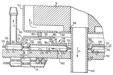
Figure 9 is a schematic cross-sectional view taken along a central axis
and illustrating a novel manifold 118 constructed according to the invention
that in its broadest applications can be used for the: transfer or
distribution of
CA 02469323 2004-06-04
-15-
two fluids. In particular, the illustrated manifold 118 can be used in
conjunction with one or more versions of a heat exchanger 16, only a portion
of such heat exchanger being illustrated in the lower left corner of Figure 9.
The manifold 118 includes a pair of manifold plates 120 and 122 consisting of
face-to-face mating ringlike plates each having inner and outer peripheral
flanges 124 and 126 and substantially annular, inner and outer bosses 128
and 130 projecting in the same direction from a first plane defined by the
outer peripheral flange 126, this plane being indicated by the letter Y.
Between the two bosses and separating same is a substantially annular,
intermediate channel 132 having a portion 134 located in the aforementioned
first plane Y. The channel 132 has a series of spaced apart openings 136,
which can be circular, for the passage of a first fluid, for example a heat
exchanging fluid such as oil, between the two intermediate channels of the
manifold. At least one of the intermediate channels 132 and preferably both of
these channels have radially extending ribs 138 formed about the
circumference of the channel or channels and extending substantially across
the channel or channels 132. These ribs are similar in their construction and
arrangement to the aforementioned radially extending ribs 76 in the above
described heat exchanger and they serve a similar purpose. The radial ribs
138 are formed between and separated from the openings 136 formed in the
channels and the ribs form cross-over passages that permit a second fluid; for
example, a second heat exchanging fluid such as a coolant, to flow radially
between the inner and outer bosses 128, 130. In the illustrated embodiment
of Figure 9, the flow of first and second heat exchanging fluids through the
adjacent heat exchanger 16 and through the manifold 118 is indicated by
arrows on the left side of the figure. Again, the letter O has been used to
indicate the flow of oil and the letter C has been used to indicate the flow
of a
coolant such as water. It will be particularly noted that, in the illustrated
version, oil passes downwardly through a central passageway formed by
threaded pipe 140, this oil having passed through a cylindrical oil filter 14,
only a portion of which is shown in Figure 9. The oil flows through one or
more apertures 142 formed in the bottom of an oil filter housing 144. The
CA 02469323 2004-06-04
-16-
threaded top end of the pipe 140 can be connected by its threads 146 to a
central opening formed in the bottom of the filter housing 144. The pipe 140
extends through a central hole 148 formed in top plate 150 which can be the
closure plate of the heat exchanger 16. Pipe 140 also extends through a
central aperture 152 farmed in the manifold plate s 120, 122.
The inner boss 128 of the bottom manifold plate 120 has at least one
port or hole 154 formed for the passage of the second fluid, for example the
coolant or water, into or out of a sealed first space 156 formed by the two
inner bosses 128. It will be appreciated that the space 156 is sealed by the
seal joint formed between the two inner peripheral flanges 124 and between
the flat portions 134 of the channels.
The aforemantio~ed top closure plate 150 has a first series and a
second series of additional holes distributed around the central hole 148. The
first series of holes 158 are aligned in a radial direction with an adjacent
one
of the intermediate channels 132 while the second series of holes 160 are
aligned with the holes or ports 154 in the inner boss of the bottom plate for
the passage of the second heat exchange fluid, ie. the coolant. As can be
seen from Figure 9, the manifold 118 is mounted on the top plate 150 of the
heat exchanger and is sandwiched between the top plate and the filter
housing 144.
At feast one of the outer bosses 130 is formed with at feast one port
162 formed for the passage of the second fluid into or out of a sealed space
164 formed by the two outer bosses 130. ft will be understood that the space
164 is sealed by the joining together of the two outer peripheral flanges 126
and the joining of the portions 134 of the channels. The second fluid, for
example, coolant C can flow upwardly as shown through a suitable pipe or
tube 166. It will thus be seen that the second fluid such as the coolant is
effectively routed by the manifold 118 from an inside location below the
filter
14 to a readily accessible location located radially outwardly from the filter
housing 144.
The manifold also includes means extending over one side of the
manifold plates 120, 122 (for example, the top side as shown in Figure 9) for
CA 02469323 2004-06-04
-17-
sealingly enclosing the adjacent intermediate channel 132 of the manifold
plates. The preferred illustrated form of this enclosing means is a third
plate
indicated at 170, this third plate being provided with one or more apertures
172 formed therein and forming a flow passage for the first fluid (for example
oil) to flow between the openings 136 in the intermediate channels and the
apertures 172. Preferably there are a series of small apertures 172
distributed
about the circumference of a substantially annular, centrally located boss 174
formed on the third plate. This boss 174 projects upwardly from a plane
defined by an outer peripheral flange 176 of the third plate. Preferably there
is
also an inner peripheral flange 178 which is firmly connected to the inner
boss
128 of the plate 122. As illustrated, the holes 172 are formed in a side wall
180 of the boss 174.
The preferred illustrated manifold is adapted to form a seat to support
one end of the filter housing 144 and a suitable annular seal or gasket 182
can be mounted between the top of the boss 174 and the bottom end of the
filter housing 144. If desired, or if required, there can also be an annular
seal
or gasket sealing the joint between the inner peripheral flanges 124 and the
pipe 140. As shown in Figure 9, in the preferred ernbodiment of the manifold,
the inner and outer bosses 128 and 130 each have a portion 184, 186 that is
located in a common second plane indicated by the line X in Figure 9. The
second plane is spaced apart and parallel to the first plane Y defined by the
outer peripheral flanges. Preferably the aforementioned portions 184 and 186
are planar and as illustrated, the inner portion 184 is substantially wider
than
the outer portion 186.
It will also be appreciated that the third plate 170 preferably is a third
ringlike plate which has inner and outer peripheral flanges. It will be
appreciated by one skilled in the art that the third or upper plate 170 can
also
be different from the plate shown. For example, it can be formed as a flat
plate with little or no boss formed thereon. if the third plate is made flat,
it can
be a thicker plate than the illustrated third plate and formed with channels
or
grooves to permit the necessary transfer of the heat exchanging fluid such as
CA 02469323 2004-06-04
-18-
oil to the desired inner location. Also, although the third plate 170 is shown
with an outer flange 176 that extends entirely over the flat portion of the
outer
boss 130, it is also possible to make the plate with little or no outer
peripheral
flange. In this case, the pipe 166 can be connected directly to the upper
outer
boss 130.
Turning now to yet another embodiment of a plate and flow
augmentation means that can be used to form a stacked plate heat
exchanger, this embodiment is shown in Figure 11 wherein the plate is
indicated generally at 190. In this embodiment, the flow augmentation means
is an expanded metal turbulizer 192. The turbulizer has an annular shape and
generally covers the intermediate area 40. The turbulizer can be located in
either the inner flow passages 42 between the plates or in the outer flow
passages 50 and preferably is located in both the inner and outer flow
passages. The turbulizer can be formed of a material other than expanded
metal, such as plastic mesh. Figure 11 is a view of the plate 190 looking at
the oil side or outside of a plate pair. The turbulizer 192 can be any type of
known turbufizer. fn one form of turbulizer there are rows 194 of S-curved
ripples or waves having rounded tops and bottoms, these waves being of
uniform size with the waves 196 in one row being staggered with respect to
the waves in the adjacent rows. Each turbulizer has a generally flat, annular
shape with the thickness or height of the turbulizer preferably being
substantially equal to but no greater than the height of the inner ar outer
flow
passageway in which it is located.
Some forms of turbulizers will have a flow resistance that varies in a
particular direction. Assuming that the turbulizer 1'92 does have variable
flow
resistance and, for example, has less flow resistance in the up and down
direction as seen in Figure 11, the apertures or holes in the outer primary
boss can be varied in size in order to help maintain a uniform radial flow
between the plates and about the circumference of the turbulizer. In the
illustrated plate 190 of Figure 11, the holes in the outer primary boss vary
from circular holes 58a to somewhat elongated, elliptical holes 58b and 58c to
relatively large, elongated holes or openings 58d. In a similar manner, it is
CA 02469323 2004-06-04
-19-
also possible to vary the size of the holes 57 in the inner primary boss of
the
plate although only circular holes 57 are shown ins Figure 11. It is also
possible to vary the size of the holes 59 and 60 formed in the inner and outer
secondary bosses 44 and 46
in order to compensate for a variation in the flow resistance of the
turbulizer
through which the second heat exchanging fluid or coolant passes.
Figure 12 illustrates another embodiment of a heat exchanger, this
embodiment being generally indicated at 210. The heat exchanger 210 can
have a rectangular (or square) shape in plan view and has an over all box-like
configuration. In addition to a top closure plate 212 and a bottom closure
plate 214, the illustrated embodiment has a plurality of stacked plate pairs
216 consisting of face-to-face mating plates 218, one of which is shown in
plan view in Figure 13. Each plate 218 has at least one edge flange and the
illustrated preferred plate has two edge flanges 2:?0 and 222 extending along
opposite long edges thereof. Each plate also has first and second spaced
apart, elongate primary ridges 224 and 226 each having a portion thereof
located in a common first plane P1 (similar to the primary bosses 36 and 38 of
the annular version of the heat exchanger) indicated in Figure 14. The edge
flanges 220, 222 also lie in this common first plane. Also, each plate has at
least one elongate secondary ridge and the illustrated preferred embodiment
has two elongate secondary ridges 228 and 230 located in a second plane P3
(also indicated in Figure 15) spaced from the first plane P~ and substantially
parallel thereto, these secondary ridges being analogous to the inner and
outer secondary bosses 44 and 46 of the annular heat exchanger. Each of
the secondary ridges is provided between one of 'the edge flanges 220, 222
and a respective one of the primary ridges 224, 226. Each plate also has an
intermediate area, which can have a rectangular shape, this area being
indicated at 232. The intermediate area is located between the first and
second primary ridges 224 and 226. It will be understood that the
intermediate areas of each plate pair has spaced apart portions to form an
inner flow passage 236 between the plates. As can be seen clearly from
Figures 13 and 14, both the primary ridges and the secondary ridges have
CA 02469323 2004-06-04
-20-
openings 238 and 240 formed therein for the passage of first and second
heat exchanging fluids respectively. The secondary ridges are arranged such
that in back-to-back plate pairs, the secondary ridges 228, 230 are joined
(for
example, by a brazing process) and their respective openings 240 (which can
be elongate slots as shown in Figure 14) communicate to define two
manifolds (in the preferred embodiment) located on opposite sides of the heat
exchanger for the flow of the second heat exchanging fluid, for example, the
coolant or water as indicated in Figure 12.
As illustrated, the coolant C can enter through one or more apertures
or slots 242 formed in the bottom closure plate 2114. After the coolant passes
horizontally through the heat exchanger (as seen in Figure 12) from one side
thereof to the other, the coolant flows out of the heat exchanger through the
right side manifold indicated generally at 244 and the coolant passes out
through a series of outlet openings 246 (which can also be slots, if desired)
formed in the top closure plate 212. It will be appreciated that, as in the
annular version, it is possible to eliminate or avoid one of the left manifold
or
the right side manifold 244 for the second heat exchange fluid by enclosing
the heat exchanger in a suitably sealed housing that covers one side of the
heat exchanger 210 or by providing a separate manifold member (see Figures
14A and 14B). For example, the right side manifold 244 can be eliminated if
one sealingly encloses the side 250 of the heat exchanger by a suitable
housing or cover plate, leaving a generally uniform gap for the flow of the
coolant between the side 250 of the heat exchanger and the inner wall of the
housing. In such version of the heat exchanger, the individual plates can
terminate along an edge flange located at 252.
The intermediate areas of the back-to-back rectangular plate pairs
define outer flow passages 256. The outer flow passages 256 can be the
same height as the inner flow passage 236 in which case the distance
between planes PZ and P~ is half the distance between planes P3 and P~. The
passages 256 can also be constructed so as to have a different height than
the passages 236 (for example, to accommodate different fluid flow rates).
The primary ridges 224 and 226 include ribs 260 extending transversely
CA 02469323 2004-06-04
-21-
across the width of each primary rib and distributE:d along the length of each
primary rib. These ribs 260 are located between and separated from the
openings 238 formed in the primary ridges and they form cross over
passages that permit the second heat exchanging fluid to flow transversely
across the primary ridges and through the inner flow passages 236. Again,
these ribs can have a uniform height or they can have tops that slope from
one end to the opposite end.
Again, as in the annular version of the heat exchangers, the heat
exchanger 210 of Figure 12 is also preferably provided with flow
augmentation means that can be located in either the inner flow passages
236 or the outer flow passages 256 and they preferably are located in both
the inner and outer flow passages. In the embodiment illustrated by Figures
12 and 13, the flow augmentation means indicated generally at 262
comprises a plurality of alternating ribs 264 and grooves 266 formed in the
intermediate area 232 between the respective first and second primary
ridges. The ribs 264 and grooves 266 are angularly disposed so that the ribs
and the grooves in the mating plates cross forming an undulating inner flow
passage between the pairs of plates and the ribs and grooves in adjacent
back-to-back plate pairs cross forming undulating outer flow passages
between the plate pairs.
In the rectangular version of the heat exchanger, the preferred ribs and
grooves are elongate and straight as illustrated in Figure 13, but it will be
appreciated that they could also be somewhat curved in the form of a spiral or
involute curve, if desired. The term "angularly disposed" as used herein to
describe the ribs and grooves in the rectangular or box-like heat exchangers
of this invention means that the rib or groove extends at an angle to the
perpendicular line that extends between the primary ridges and that is
perpendicular thereto. auch a perpendicular Fine i;~ indicated in dashed lines
at Z in Figure 13.
It will be appreciated that other forms of flow augmentation means
other than the illustrated ribs and grooves can be used in the rectangular
version of the heat exchanger 210. For example, one can employ generally
CA 02469323 2004-06-04
-22-
flat, rectangular turbulizers similar in their construction to that
illustrated in
Figure 11 (except for their shape) in at least one of the inner and outer flow
passages and preferably in both the inner and outer flow passages. Again,
the construction of such turbufizers is well known in the heat exchange art
and a detailed description herein is deemed unnecessary. As a further
alternative, the flow augmentation means can comprise a plurality of spaced-
apart dimples extending into at least one of the inner flow passages and the
outer flow passages and preferably into both of these passages.
It will be appreciated that Figure 12 is a transverse vertical cross-
section of the heat exchanger with a short end portion of the heat exchanger
cut away for ease of illustration. It will be further appreciated that the
edges of
the stacked plate pairs are sealed closed by joining edge flanges which
preferably extend around the entire perimeter of each plate as illustrated in
Figure 13. Thus, in addition to the aforementioned edge flange 220 and 222
on the opposite long sides of the plate, there are also side edge flanges 270
and 272 that extend between the flanges 220 and 222. In this way, it will be
appreciated that both the inner flow passages and the outer flow passages
are enclosed along both of their short side edges preventing the heat
exchanging fluids from escaping through these edges. It will be appreciated
that there are other ways of closing these end edges of the plates other than
by the use of edge flanges, if desired. For example, flat end plates (not
shown) can extend across the opposite ends of the plate pairs to enclose and
seal these ends. These end plates can be sealingly attached by known
brazing processes.
In the embodiment of Figure 12, the illustrated top closure plate 212
encloses or covers the two secondary ridges 228 and 230 at the top end of
the stack of plate pairs. However, it will be appreciated that if the
secondary
ridges on one side are omitted so that there is only a manifold on the
opposite
side for the second heat exchanging fluid, then the top closure plate would
enclose or cover only one of the secondary ridges at the top end. Also, the
illustrated top closure plate includes flow ports for the flow of both the
first
heat exchanging fluid and the second heat exchanging fluid therethrough but
CA 02469323 2004-06-04
-23-
again, if the secondary ridges on one side were omitted, for example, on the
right side in Figure 12, the top closure plate can have only flow ports for
the
first heat exchanging filuid or oil. The same comments apply equally to the
bottom closure plate 214. It will further be noted that if the uppermost plate
218 is omitted from the heat exchanger of Figure 12 so that the top closure
plate 212 is lowered by the thickness of one plate, then the top closure plate
would effectively be used to enclose or cover the two primary ridges 224 and
226 of the top end of the stack of plate pairs instead of the secondary
ridges.
Figure 14A is a partial perspective view of a rectangular heat
exchanger for which only three plates are shown in vertical section. This
embodiment indicated generally by reference 450 has many features in
common with the embodiment of Figures 12 and 13 and only the differences
will be described herein. The heat exchanger has no right side secondary
ridge 230 but the plates terminate on the right side edge with the edge flange
252. The right side of the heat exchanger is enclosed by an edge manifold
452 having a tubular pipe 454 connected to an erud thereof. The pipe 454 can
be an inlet or an outlet for the coolant (C). The illustrated manifold has a
generally semi-cylindrical wall 456 which preferably is tapered from one end
to the other as shown in both Figures 14A and 14~. There are also top and
bottom flat wall extensions 457, 458 with edge flanges 460, 462 that are
sealingly joined to the top and bottom plates of the heat exchanger with only
part of the top plate 463 shown. It will be understood that if the manifold
452
is an inlet manifold, the coolant will enter the inner flow passages 236
between each pair of plates 218' by passing into the elongate slots 464
formed between two edge flanges 252.
If desired, the top plate 463 and bottom plate of the heat exchanger
can be formed with locating tabs 466 on corners thereof adjacent to the edge
manifold. These tabs are inserted into corner recesses formed in corners of
the edge manifold, this arrangement helping to ensure that the manifold is
correctly positioned before it is permanently attached such as by brazing.
Turning now to the heat exchanger illustrated in Figure 15 and its top
and bottom manifolds as illustrated in Figures 16 and 17, this heat exchanger
CA 02469323 2004-06-04
-24-
indicated generally at 270 has a number of features in common with the
above described rectangular or box-like heat exchanger 210 of Figure 12.
Accordingly, only those features of the heat exchanger 270 which differ from
the heat exchanger 210 will be described herein. This heat exchanger has a
plurality of stacked plate pairs 272 consisting of face-to-face mating plates
274. Each plate has edge flanges, including edge flanges 276 and 278
extending along edges thereof, preferably all four edges thereof, and first
and
second pairs of spaced apart, elongate primary ridges 280 and 282. Each of
these ridges has at least a portion thereof located in a common first plane
(identified as P~ in Figure 18) with its edge flanges such as the illustrated
flanges 276 and 278. Each plate also has three spaced-apart elongate
secondary ridges 284, 286 and 288. Each of these ridges has a portion
thereof located in a second plane (identified as Ps in Figure 18) which is
spaced from the first plane and is parallel thereto. The secondary ridges
include a central ridge 286 and two outer ridges 284, 288 located on opposite
sides of the central ridge and spaced a substantial distance therefrom. As can
be seen from Figure 1 b, each of the outer ridges 284, 288 is separated from
the central ridge by one of the pairs, 280, 282 of primary ridges and an
intermediate area 290, 292 located between the respective pair of primary
ridges. As in the other embodiments of the present heat exchangers, the
intermediate areas 290, 292 of each plate pair have spaced-apart portions
forming inner flow passages 294 between the plates of the pair. Both the
primary ridges 280, 282 and the secondary ridges 284, 286 and 288 have
openings 296 and 298 for the passage of first and second heat exchanging
fluids respectively, these fluids being represented again symbolically by
letters O and C in Figure 15. The secondary ridges 284, 286 and 288 are
arranged such that in back-to-back plate pairs, the secondary ridges are
joined and their respective openings thereof communicate to define three
separate manifolds 300, 302 and 304 for the flow of the second heat
exchanging fluid which can be the coolant or water C. Also, the intermediate
areas 290, 292 of the back-to-back plate pairs have spaced apart portions
defining outer flow passages 306 through which the second heat exchanging
CA 02469323 2004-06-04
-25-
fluid can flow. As in the embodiment illustrated by Figures 12 and 13,
preferably all of the primary ridges 280, 282 include ribs 260 that extend
transversely across the width of each primary ridge and that are distributed
along the length of each primary ridge. These ribs, which can be the same in
their arrangement and construction as those illustrated in Figure 13, are
located between and separated from the openings 296 in the primary ridges
and they form cross-over passages that permit the secondary heat
exchanging fluid to flow transversely across a respective one of the pairs of
primary ridges and through the inner flow passages 294.
As with the previous embodiments, flow augmentation means can be
located in either the inner flow passageways 294 or the outer flow passages
306 and preferably such flow augmentation devices are located in most of the
passages. Again, the flow augmentation means can take the form of
alternating ribs and grooves arranged in the manner illustrated in Figure 13,
these ribs and grooves formed in the intermediate areas 290, 292 located
between the pairs of primary ridges 280, 282. Alternatively, the flow
augmentation means can comprise generally flat, rectangular turbulizers
whose construction is known her se, located in either the inner flow passages
or the outer flow passages and preferably in both these sets of passages. A
further alternative is the use of a plurality of dimples extending into either
the
inner flow passages, the outer flow passages or preferably into both sets of
passages.
Figures 16 and 17 illustrate top and bottom manifold plates that can be
used in the heat exchanger 270 of Figure 15. With respect to the top manifold
plate 310, it can either replace the top closure plai:e 312 shown in Figure 15
or it can be mounted in a close fitting, sealing manner on top of the plate
312.
The illustrated plate 310 has an elongate central groove or recess 314
extending along its bottom surface and extending over all of central holes 316
of the plate 312 or, in the case of a direct mounting, extending over all of
the
central openings 298 formed in the top central secondary ridge 286, the
location of these holes being indicated by the dashed holes 316 indicated in
Figure 16. Instead of small circular holes 298, these central holes can be a
CA 02469323 2004-06-04
-26-
few elongate slots 298' as illustrated in the plate shown in Figure 18.
Extending along opposite sides of the groove 314. are two further elongate
grooves 318 and 320 which form parallel arms that are joined by a connecting
groove 322. Each of the grooves 318 , 320 extend over all of the respective
outer row of holes 322 formed in the top closure plate 312 or over the
respective row of holes or openings 296 formed in the outer primary ridges.
The first heat exchanging fluid or oil can pass out from beneath the plate 310
through a short, end passageway 324, the end of which can be connected to
a suitable pipe or hose (not shown) for example. The second heat exchange
fluid or coolant that passes into the central groove 314 can flow therefrom
through a central opening 326 formed in the centre of the manifold plate.
Again, the top end of the opening 326 can be connected to a suitable pipe or
hose for the coolant.
The bottom manifold plate 330 works in a similar fashion to the plate
310. However, the bottom manifold plate has a wider, elongate central groove
332 that extends most of the length of the plate. 'f'he groove 332 extends
over
the bottom end of two rows of apertures 334 formed in the bottom closure
plate 336 or, in the case where the manifold plate 330 replaces the bottom
closure plate 336 of Figure 15, the recess 332 extends over the openings 296
of the two inner primary ridges 280, 282. The location of these openings 334
is indicated in dashed circles in Figure 17. Located on opposite sides of the
central groove are two elongate parallel grooves 340 and 342 which are
connected at one end by a connecting passageway 344. Extending centrally
from the passage 344 is a short end passageway 346 which, at its outer end,
is connected to a suitable pipe or tube for the transfer of the second heat
exchanging fluid or coolant. Again, the two grooves 340, 342 either extend
over the rows of apertures 350, 352 formed in the bottom closure plate or, in
the case where the plate 330 replaces the bottom plate of Figure 15, these
grooves extend over the bottom of the bottom openings 298. The location of
the openings 350, 352 relative to the manifold plate is indicated by dashed
circles in Figure 17. Preferably the openings 350, 352 and the openings 298
in the plates are smaller than, for example one haNf the size of, the
apertures
CA 02469323 2004-06-04
-27-
316 and the openings 298 in the central secondary ridge. It will be understood
that oil can be fed into 'the elongate central groove 332 by means of a large
central aperture or hole 360 formed in the centre of the plate 330. Again, a
suitable pipe or tube can be connected to the outside of the plate 330 to
transfer the first heat exchanging fluid or oil to the central groove 332.
Figures 18 and 19 illustrate one form of heat exchange plates 274' that
can be used in a rectangular type of heat exchanger of the type shown in
Figure 15. The flow augmentation means, which as indicated can take various
forms, as been omitted from these figures for ease of illustration. In these
plates the single central secondary ridge 286' is substantially wider than the
other ridges to accommodate the larger fluid flow through the central
manifold. Also, the ridge 286' has relatively large, elongate slots
298° formed
therein allowing for substantial flow of coolant in the vertical direction
perpendicular to the plates 274'. Each plate 274' has an edge flange 278' that
extends about the perimeter of the plate and that is used to seal this
perimeter when connected to the edge flange 278' of the other plate in the
pair. It will be noted that the intermediate areas 290' lie in a plane P2 that
is
parallel to and between the two planes P~ and P3. The illustrated ribs 260
have flat tops that lie in the plane P3.
It will be understood that various modifications and changes can be
made to the manifold described herein without departing from the spirit and
scope of this invention. Accordingly, ail such modifications and changes as
fall within the scope of the accompanying claims are intended to be part of
this invention.
30