Note: Descriptions are shown in the official language in which they were submitted.
CA 02469351 2004-05-31
-I_
Fl PLACE ENCLOSURE
Teclzucal Field
This invention relates generally "'o fireplaces, and, more specifically, to
prefabricated fireplace enclosures.
Raekound of Invention
In recent years, as many as sixty percent of new hones have been built with at
least one fireplace. Manynew buildings incorporate one or more fireplaces as
well. The
advent of "direct vent" fireplaces has allowed for relatively inexpensive
installation of
new fireplaces in new and existing homes and structures, Traditional masonry
work, on
the other hand, has become prohibitively expensive and time consuming for
many.
Fireplace enclosures which surround fireplaces are typically built by
contractors
on site with the same materials which form the exterior of the home or
building, e.g.
wood, composites and siding. Therefore, in addition to building a. wood or
composite
frame, insulation, refractory lining and/or masonry work may be required
before a
fireplace may be installed in a fireplace enclosuure. Such additional work
must be
performed at the construction site, with associated labor costs, and often
takes days to
complete.
It is estimated that more than seventy-five percent of all fireplaces
installed today
are factory-built and shipped to the construction site. Most fireplaces
shipped are direct
vent fireplaces which vent directly outside, so there is no need for a
traditional chimney
or masony. In addition, they may be installed inexpensively, without the use
of skilled
craftsmen. "Rear vent, direct vent" fireplaces vent ii-onr the rear of the
fireplace,
collecting combustible air From outside and pumping the by-products of burning
gases
outside. "Top vent, direct vent" fireplaces vent from the top of the fireplace
using the
same principles. Approximately eighty percent of new direct vent fireplaces
are rear
vent, while twenty percent are top vent, A "13-vent" system is a top vented
system that
uses room air for combustion. Some direct vent systems operate more
efficiently when
the vent termination is above the roof line of the associated home or
building.
CA 02469351 2004-05-31
-2-
Fireplace enclosures which project outward from, an associated living or
office
space, for example, require some method of support. This is typically
accomplished by
unattractive bracing or reinforcement, expensive masonry or concrete work, or
the
extension of a support member into the associated 1. iving or office space,
(e.g., a support
member extending four feet inside to support a two-foot deep enclosure). In
addition,
existing fireplace enclosures often require rerouting of mechanical,
electrical and/or
plumbing features.
prior art discloses pref .bricated framed fireplaces (e.g., U.S. flat. No.
6,374,822
(Lyons, et al.)) which provide a fireplace box with an attached surrounding
framework
of building materials which becomes a permanent part of the wall or structure
to which
it is attached. The prior art, .hhowever, does not provide a fireplace
enclosure adapted for
cornpact packaging or shipping in knock-down condition. Nor does it disclose a
modular
fireplace enclosure which is adjustable and flexible in terms of height. For
example,
some top vent, direct vent systems, either for cosmetic purposes or for
efficiency, require
a fireplace enclosure or flue which extends upward along a substantial portion
of the
exterior wall of the house or building in which the fire place is installed.
The present
invention solves this problem by providing stackable, essentially modular side
and rear
panels, whereas the prior a.rt discloses a one-piece construction of parts
integrally molded
together.
In addition, the prior art requires a rough openi,.n of substantially the same
size
as the fireplace box, whereas the present invention, because it is secured to
the exterior
wall of the structure, from the outside, has no such limitation. In addition,
the prior art,
because it includes brackets and/or flanges which connect. to the interior of
the associated
structure, must be installed, at least in part, from the interior of the
structure. The prior
art limits access from the extcrior, resulting in difficulty or inconvenience
in installing
associated gas and/or electric lines. Among other things, the present
invention
diminishes or eliminates such inconvenience and diminishes or eliminates the
need to
reroute such items as electrical andt plumbing lines and mechanical members.
There exists a need for a simple, self-supported enclosure which is
prefabricated and capable of being shipped in knock-down or disassembled
condition by
standard methods such as UPS, FedEx and U.S. Mail; which may be assembled
quickly
CA 02469351 2004-05-31
-3-
and efficiently at the construction site without the need for skilled
contractors or
additional materials such as insulation, Sheetrock or bracing members; which
may be
assembled from the exterior- of the associated structure; which may be used in
conjunction with a wide variety of fireplaces available to the public; which
provides for
variable height by stacking to accommodate various styles of fireplaces and
configurations; and/or which allows efficient access frora.:a the exterior of
the associated
home or building to electric and gas lines.
Disclosure of the Invention
With parenthetical reference to the corresponding elements or portions of the
disclosed embodiment, merely for purposes of illustration and not by way of
limitation,
the present invention provides an improved fireplace enclosure, which is
prefabricated
and configured and arranged for simple and compact packaging and delivery to
the
construction site. The fireplace enclosure may be installed at the
construction site
quickly and efficiently, without the need for additional bracing, Sheetrock or
insulation,
and without the need for skilled craftsmen or experienced contractors. If the
home or
building to which the fireplace enclosure will be attached has a rough opening
to accept
a fireplace, the improved fireplace enclosure maybe installed in minutes with
only a drill
and machine screws. Because the fireplace enclosure may be installed piece by
piece
from the outside of the associated structure, the installer is provided with
easy access to
gas and electric lines.
One aspect of the invention provides a prefabricated fireplace enclosure (10)
adapted for compact packaging and connection to an exterior supporting wall of
a
structure, having a first side panel (20) and a second side panel (21); first
(40) and second
(44) mounting members securable to the supporting wall for supporting the
first and
second side panels, respectively; a rear pane! (22, 23) and a bottom panel
(24) adapted
for positioning between the first and second side panels; a roof assembly (25)
adapted for
support by the first and second side panels; wherein each of the panels,
mounting
members and roof assembly are configured and arranged so as to allow for
compact
packaging and shipment to the construction site in a disassembled condition.
In this
CA 02469351 2004-05-31
--
aspect of the invention, the resulting fireplace enclosure assembled from the
foregoing
components forts a part of the exterior of the structure to which it is,
connected.
In another aspect of the invention, the fireplace enclosure includes two
tapper side
panels (27, 29), two upper mounting members (30, 31) securable to the
supporting wall
for supporting the upper side panels, and an upper rear panel (28) positioned
between the
two upper side panels, wherein the upper side panels and Upper rear panels are
configured
so as to be vertically stacked upon the corresponding side panels and rear
panels beneath
then (20, 21, 22 ). This aspect of the invention provides for adjustment of
the height of
the fireplace enclosure. in other words, consecutive side and rear panels
maybe stacked
upon each other, for decorative or efficiency purposes, as high as the roof
line of the
associated home or building.
In another aspect of the invention, the upper rear panel has two vertical edge
portions (28A, 28B), a first lateral channel (28C) extending parallel to a
first vertical edge
portion (28A), and a second lateral channel (28D) extending parallel to a
second vertical
edge portion (28B), wherein the first lateral channel is aclapted to receive
the first upper
side panel, and the second lateral channel is adapted to receive the second
upper side
panel.
Yet another aspect of the invention provides for an upper rear insulation
pocket
in the upper rearpanel which is defined by the exterior wall ofthe upper rear
panel (28E)
and an interior surface (28F) with a width shorter than the w iidth of the
exterior wall. Iz
another aspect, the upper rear insulation pocket has two vertical edge
portions which
define lateral channels in the upper rear panel.
In another aspect of the invention, the rear panel (22, 23) has two vertical
edge
portions (22A, 22B, 23A, 2313), a first lateral channel (22C, 23C) extending
parallel to
a first vertical edge portion (22A, 23A), and a second lateral channel (22D,
23D)
extending parallel to a second vertical edge portion (2213, 23B) wherein the
first lateral
channel is adapted to receive the first side panel. and the second lateral
channel is adapted
to receive the second side panel. in another aspect, the rear panel includes a
rear
insulation pocket defined by the exterior wall of the rear panel (22E, 23E)
and an interior
surface (22F, 23F) with a width shorter than the width of the exterior wall.
In yet another
CA 02469351 2004-05-31
-5-
aspect, the rear insulation pocket has two vertical edge portions which define
the first and
second lateral channels of the rear panel.
In another aspect of the invention, the rear panel comprises a substantially
rectangular top portion (22) and a substantially rectangular bottom portion
(23). In this
aspect, the top portion has a height h, the bottom portion has a height
substantially equal
to h, and the first and second side panels have a height substantially equal
to 2h.
Another aspect of the invention provides a first (40) and second (44) mounting
members or brackets, wherein the first and second side panels are adapted to
be mounted
on the corresponding first and second mounting bracket. In another aspect, the
first and
second mounting brackets are substantially U-shaped.
In another aspect of the invention, the mounting members comprise a horizontal
mounting portion (42, 46). a vertical mounting portion (41, 45) and a brace
portion (43,
47) which is positioned between the horizontal mounting portion and the
vertical
mounting portion, and which supports the horizontal mounting portion.
In another aspect, the roof assembly (25) of the present invention comprises a
pitched top portion (25A) and. two vertical side portions (25B, 25C) wherein
the roof
assembly is configured and arranged to be positioned on top of the first and
second side
panels. In another aspect oft he invention, the roof assembly is secured to
the first and
second side panels with screws (e.g. 251:3, 25E).
Several aspects ofthe invention provide that adjoining or connected members
and
panels are secured together with screws (e.g. 48A, 48B, 48C).
In another aspect of the invention, a top panel (26) is provided which may be
positioned on top of the first and second side panels, and beneath the roof
assembly. In
another aspect of the invention, the top panel includes a top insulation
pocket defined by
a top surface (26A) and an interior surface (26B). In this and many aspects of
the
invention, the top, rear, bottom and side insulation pockets comprise
insulation such as
Styrofoam insulation.
In another aspect of the invention, the top, bottor, side and rear panels, and
the
roof assembly, comprise gavan.ized steel.
CA 02469351 2004-05-31
In another aspect of the invention, the first and second side panels include
side
insulation pockets defined by the corresponding exterior walls (20A, 21A) and
interior
surfaces (20B, 21B) of the respective side panels.
In another aspect of tic invention, the, bottom par el includes a bottom
insulation
pocket defined by the bottom surface (2413) and the interior surface (24A) of
the bottom
panel. In another aspect oltt=e invention, the first and second side panels
are adapted to
snap into, or interlock with, the lateral channels in the rear panel.
In another aspect of the invention, each of the top, bottom, rear and side
panels,
and the roof assembly, are substantially rectangular.
Another aspect of the invention provides a method of assembling a
prefabricated
fireplace enclosure adapts i for compact packaging and connection to an
exterior
supporting wall of a structure. In that aspect, a first side panel and P.
second side panel,
a first mounting member securable to the supporting wall, a second mounting
member
securable to said supporting wall, a rear panel and abotto
npaneladaptedforpositioning
between the first side panel and said second side panel, ;auid a roof assembly
adapted for
support by said first side l-)a iel and. said. second side panel, are
provided. The mounting
members are secured to the supporting wall. The first side parcel is secured.
to the first
mounting n rernber, and the second side panel is secured to the second
mounting member.
In addition, the rear and bottom panels are secured between the first side
panel and said
second side panel, and the roof assembly is positioned on top of the first and
second side
panels, whereby the fireplace enclosure is assembled and forms a part of the
exterior of
the structure to which it is connected.
Zn another aspect, first and second upper side panels, first and second upper
mounting members securable to said supporting wall, and an upper rearpanel
adapted for
positioning between said first upper side panel and said second upper side
panel, are
provided. The first and second upper n Counting members are secured to the
supporting
wall above the first and second mounting members, respectively. The first and
second
side panels are secured to the first and second upper mounting members, and
the upper
rear panel is positioned between the first and second upper- side panels,
whereby the
height of the fireplace enclosure may be adjusted.
CA 02469351 2011-08-19
63109-449
-7-
Another aspect of the invention provides a prefabricated fireplace
enclosure adapted for compact packaging and adapted for connection to an
exterior
supporting wall of a structure, comprising: a first side panel and a second
side panel;
a first mounting member, securable to a supporting wall, for supporting said
first side
panel, and a second mounting member, securable to said supporting wall, for
supporting said second side panel; rear panel and a bottom adapted for
positioning
between said first side panel and said second side panel; a roof assembly
adapted
for support by said first side panel and said second side panel; a first upper
side
panel and a second upper side panel; a first upper mounting member, securable
to
said supporting wall, for supporting said first upper side panel, and a second
upper
mounting member, securable to said supporting wall, for supporting said second
upper side panel; an upper rear panel adapted for positioning between said
first
upper side panel and said second upper side panel; wherein said first upper
side
panel, said second upper side panel, and said upper rear panel are configured
so as
to be vertically stacked upon a corresponding first side panel, second side
panel, and
rear panel; each of said panels, said mounting members and said roof assembly
being configured so as to allow for compact packaging and shipment in a
disassembled condition; wherein said fireplace enclosure forms a part of the
exterior
of the structure to which it is connected.
A further aspect of the invention provides a prefabricated fireplace
enclosure adapted for compact packaging and adapted for connection to an
exterior
supporting wall of a structure, comprising: a first side panel and a second
side panel;
a first mounting member, securable to a supporting wall, for supporting said
first side
panel, and a second mounting member, securable to said supporting wall, for
supporting said second side panel; a rear panel and a bottom panel adapted for
positioning between said first side panel and said second side panel; a roof
assembly
adapted for support by said first side panel and said second side panel;
wherein said
rear panel comprises two vertical edge portions, a first lateral channel
extending
parallel to a first vertical edge portion, and a second lateral channel
extending parallel
to a second vertical edge portion; said first lateral channel being adapted to
receive
CA 02469351 2011-08-19
63109-449
-7a-
said first side panel and said second lateral channel being adapted to receive
said
second side panel; each said panels, said mounting members and said roof
assembly being configured so as to allow for compact packaging and shipment in
disassembled condition; wherein said fireplace enclosure forms a part of the
exterior
of the structure to which it is connected.
A still further aspect of the invention provides a prefabricated fireplace
enclosure adapted for compact packaging and adapted for connection to an
exterior
supporting wall of a structure, comprising: a first side panel and a second
side panel;
a first mounting member, securable to a supporting wall, for supporting said
first side
panel, and a second mounting member, securable to said supporting wall, for
supporting said second side panel; a rear panel and a bottom panel adapted for
positioning between said first side panel and said second side panel; a roof
assembly
adapted for support by said first side panel and said second side panel;
wherein said
roof assembly comprises a pitched top portion and two vertical side portions,
and
wherein said roof assembly is configured and arranged to be positioned on top
of
said first side panel and said second side panel; each of said panels, said
mounting
members and said roof assembly being configured so as to allow for compact
packaging and shipment in a disassembled condition; wherein said fireplace
enclosure forms a part of the exterior of the structure to which it is
connected.
Yet another aspect of the invention provides a prefabricated fireplace
enclosure adapted for compact packaging and adapted for connection to an
exterior
supporting wall of a structure, comprising: a first side panel and a second
side panel;
a first mounting member, securable to a said supporting wall, for supporting
said first
side panel, and a second mounting member, securable to said supporting wall,
for
supporting said second side panel; a rear panel and a bottom panel adapted for
positioning between said first side panel and second side panel; a roof
assembly
adapted for support by said first side panel and said second side panel; a top
panel
adapted to be positioned on top of said first side panel and said second side
panel
and beneath said roof assembly; each of said panels, said mounting members and
said roof assembly being configured so as to allow for compact packaging and
CA 02469351 2011-08-19
63109-449
-7b-
shipment in a disassembled condition; wherein said fireplace enclosure forms a
part
of the exterior of the structure to which it is connected.
Still another aspect of the invention provides a method of assembling a
prefabricated fireplace enclosure adapted for compact packaging and adapted
for
connection to an exterior supporting wall of a structure, comprising:
providing a first
side panel and second side panel; a first mounting member for supporting said
first
side panel, and a second mounting member for supporting said second side
panel; a
rear panel and bottom panel adapted for positioning between said first side
panel and
said second side panel; a roof assembly adapted for support by said first side
panel
and said second side panel; securing said first mounting member and said
second
mounting member to a supporting wall; securing said first side panel to said
first
mounting member, and securing said second side panel to said second mounting
member; securing said rear panel and said bottom panel between said first side
panel and said second side panel; positioning said roof assembly on top of
said first
side panel and said second side panel; providing a first upper side panel and
a
second upper side panel; a first upper mounting member for supporting said
first
upper side panel, and a second upper mounting member for supporting said
second
upper side panel; and upper rear panel adapted for position between said first
upper
side panel and said second upper side panel; securing said first upper
mounting
member to said supporting wall above said first mounting member, and securing
said
second upper mounting member to said supporting wall above said second
mounting
member; securing said first side panel to said first upper mounting member,
and
securing said second upper side panel to said second upper mounting member;
positioning said upper rear panel between said first upper side panel and said
second
upper side panel; whereby said fireplace enclosure is assembled and forms a
part of
the exterior of the structure to which it is connected.
Embodiments of the invention may reduce the cost of and time
associated with fireplace construction and installation.
CA 02469351 2011-08-19
63109-449
-7c-
Embodiments of the invention may provide a fireplace enclosure
adapted for compact packaging. Embodiments disclosed herein may provide a
prefabricated fireplace enclosure which is easy and inexpensive to ship, and
which
may be shipped in knock-down or disassembled condition. Embodiments disclosed
herein may provide a prefabricated fireplace enclosure which is easy to
install.
Embodiments disclosed herein may provide a prefabricated fireplace
enclosure which requires no additional insulation, Sheetrock or support.
Embodiments disclosed herein may provide an essentially modular
fireplace enclosure with a variable height to accommodate various types of
fireplaces
and venting methods.
Embodiments disclosed herein may provide a fireplace enclosure which
permits efficient access to and installation of gas and electric lines.
Brief Description of the Drawings
Fig. 1 is a perspective view of the fireplace enclosure of the present
invention.
Fig. 2 is an exploded view of the fireplace enclosure of the present
invention.
Fig. 3 is a front view of the fireplace enclosure of the present invention.
Fig. 4 is a side view of the fireplace enclosure of the present invention.
Fig. 5 is a perspective view of the fireplace enclosure of the present
invention depicted with attached siding, roofing and vent cap.
Fig. 6 is a perspective view of the fireplace enclosure of the present
invention depicted with upper side and rear panels.
Fig. 7 is an exploded view of the fireplace enclosure of the present
invention depicted with upper side and rear panels.
CA 02469351 2011-08-19
63109-449
-7d-
Description of the Preferred Embodiments
At the outset, it should be clearly understood that like reference
numerals are intended to identify the same structural elements, parts,
portions or
surfaces consistently
CA 02469351 2004-05-31
-8-
throughout the several drawing figures, as such elements, parts, portions or
surfaces may
be further described or explained by the entire written specifications, of
which this
detailed description is an integral part. Unless otherwise indicated., the
drawings are
intended to be read together with the specification, and are to be considered
a portion of
the entire written description of this invention. As used in the following
description, the
terms "horizontal", "vertical", "left", "right", "up" and "down", as well as
adjectival and
adverbial derivatives thereof(e.g.. "horizontally", "rightwardly", "upwardly",
"radially",
etc.), simply refer to the orientation of the illustrated structure as the
particular drawing
figure faces the reader. Sir r.ilarly, the ter flis "inwardly," "outwardly"
and "radially"
generally refer to the orientation of a surface relative to its axis of
elongation, or axis of
rotation, as appropriate.
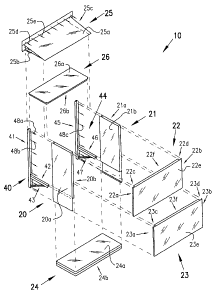
Referring now to the drawings, Fig. 1 illustrates a preferred embodiment of
the
invention in perspective vice. This embodiment or: the fireplace enclosure 10
is attached
to the exterior or supporting wall 50 of a home or building and the
corresponding framing
51 of the home or building. The embodiment includes a first side panel 20 and
a second
side panel 21, a substantially rectangular top portion of the rear panel 22
and a
substantially rectangular bottom portion of the rear panel 23, and a roof
assembly 25.
Fig. 2 provides additional detail not depicted in Fig. 1. In particular, the
embodiment includes a first mounting member 40 and a second mounting member
44,
both securable to the exterior or suipporting wall 50 for supporting the first
side panel 20
and second side panel 21, respectively. The first mounting member includes a
vertical,
U-shaped portion 41 securable to the exterior wail of the home with screws
48A, 48B,
and a horizontal, U-shaped portion 42 supported by a brace 43 for supporting
the first
side panel 20. Similarly, the second mounting member includes a vertical
portion 45, a
horizontal portion 46 supported by a brace 47, for supporting the second side
panel 21.
In this embodiment, the first side panel includes an insulation pocket defined
by
the exterior wall of the panel 20A and the interior surface of the panel 20B.
Similarly,
the second side panel includes an insulation pocket defined by its exterior
wall21 A and
interior surf ace 21B. The top portion of the rear panel 22 is defined by two
vertical edges
22A, 22B, an exterior wall 22E and an interior surface 22F, which define first
and second
vertical channels 22C, 221). Similarly, the bottom portion of the rear panel
23 is defined
CA 02469351 2004-05-31
by two vertical edges 23A, 23B, an exterior wall 23E and an interior surface
23F, which
define first and second vertical channels 23C, 23D. In this embodiment, the
top and
bottom portions of the rear panel are secured to the first and second side
panels 20, 21
with screws. In addition, the bottom panel, which is secured to the first and
second side
panels with screws, includes an insulation pocket defined by the interior
surface 24A and
a bottom surface 24B.
The roof assembly 25 includes a top pitched portion 25A and two vertical side
portions 2513, 25C. The roof assembly 25 is securable to the exterior surface
of the home
or building 51 with screws 25D, 25E, and rests upon the side panels 20, 21 and
top
portion of the rear panel 22, to which it is secured with screws.
In addition, this embodiment includes a top panel 26 having an insulation
pocket
defined by a top surface 26A and abottom surface 26B. The top panel is also
secured
to the first side panel 20 and second side panel 21 with screws.
The U-shaped channels on the side of the first side panel and second side
panel
which face the mounting brackets 40, 44 are configured such that the
respective channels
fit over or snap on the corresponding U-shaped horizontal portion 41, 45 of
the
corresponding mounting bracket or member. The channels in the rear panels 22C,
22D,
23C, 23D snap on or fit over the corresponding sides of the first side panel
20 and second
side panel 21, and may be mounted or attached with screws.
Fig. 3 is a front view of this embodiment which depicts the attachment of the
fireplace enclosure to the exterior or supporting wall 50 of the home or
building and the
framing 51 with a number of= screws, e.g. 48A, 48I3.
Fig. 4 is a side view of thefi:replace enclosure in this embodiment which
shows
the attachment of the fireplace enclosure to the exterior or supporting wall
50 of the home
or building and framing 51 with a number of screws.
Fig. 5 is an illustration of the fireplace enclosure which i icludes siding
61, a vent
cap 60 and roofing 62 which maybe added to the fireplace enclosure after
installation of
the fireplace enclosure,
Fig. 6 is an illustration of another embodiment of the invention which
includes
first and second top side panels 27, 29 and a top rearpanel 28 which are
stacked upon the
corresponding first and second side panels 20, 21 and rear panel 22. As shown
in Fig. 7,
CA 02469351 2011-08-19
63109-449
-10-
an exploded view of Fig. 6, this embodiment includes upper mounting members
30, 31
which are U-shaped and stacked upon the corresponding lower mounting members
40,
44. The upper rear panel 28 includes two vertical edge portions 28A, 28B, an
exterior
wall or surface 28E and an interior surface 28F, which define vertical
channels 28C, 28D,
which vertical channels snap on or fit around the corresponding upper side
panels 27, 29.
The upper rear panel may be secured or affixed or attached to the
corresponding upper
side panels with screws. The described surfaces of the upper rear panel define
an
insulation pocket which may include Styrofoam insulation, which each of the
previously
described insulation pockets may include. In addition, the upper side panels
27, 29
include insulation pockets defined in the same manner as the insulation
pockets in the
first side panel and second side panel.
Modifications
The present invention contemplates that many changes and modifications may be
made. For example, other means may be used to secure the side panels to the
mounting
members, and to secure the mounting members to the supporting wall. The
various
panels and mounting members may also be manufactured from composite materials
or
plastics, for example.